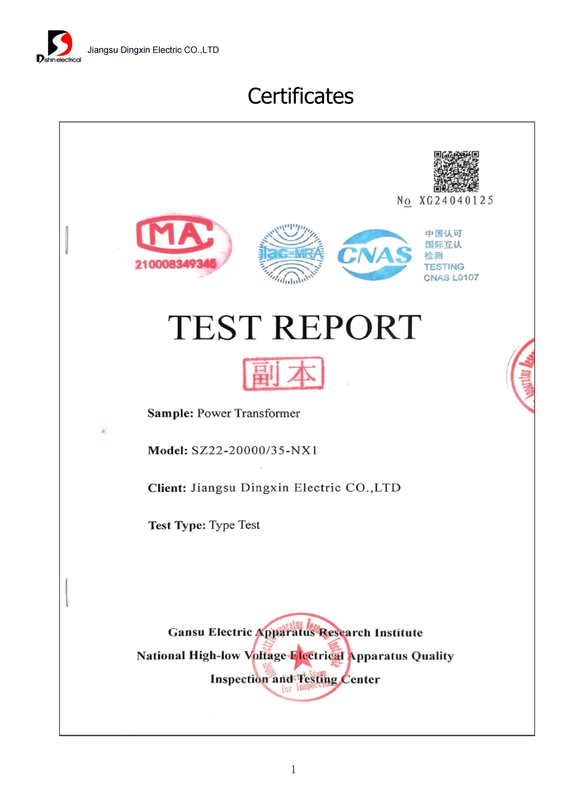
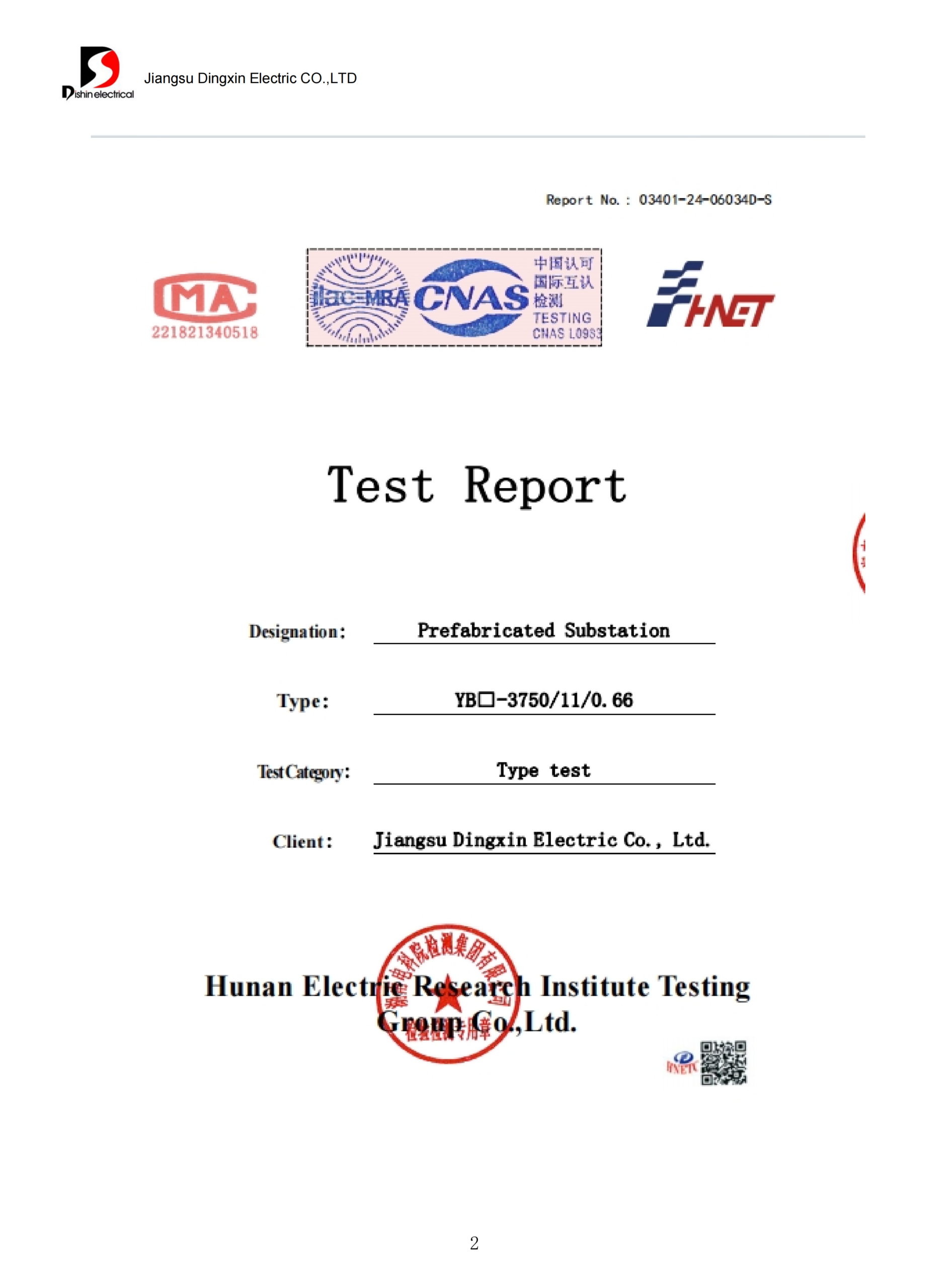
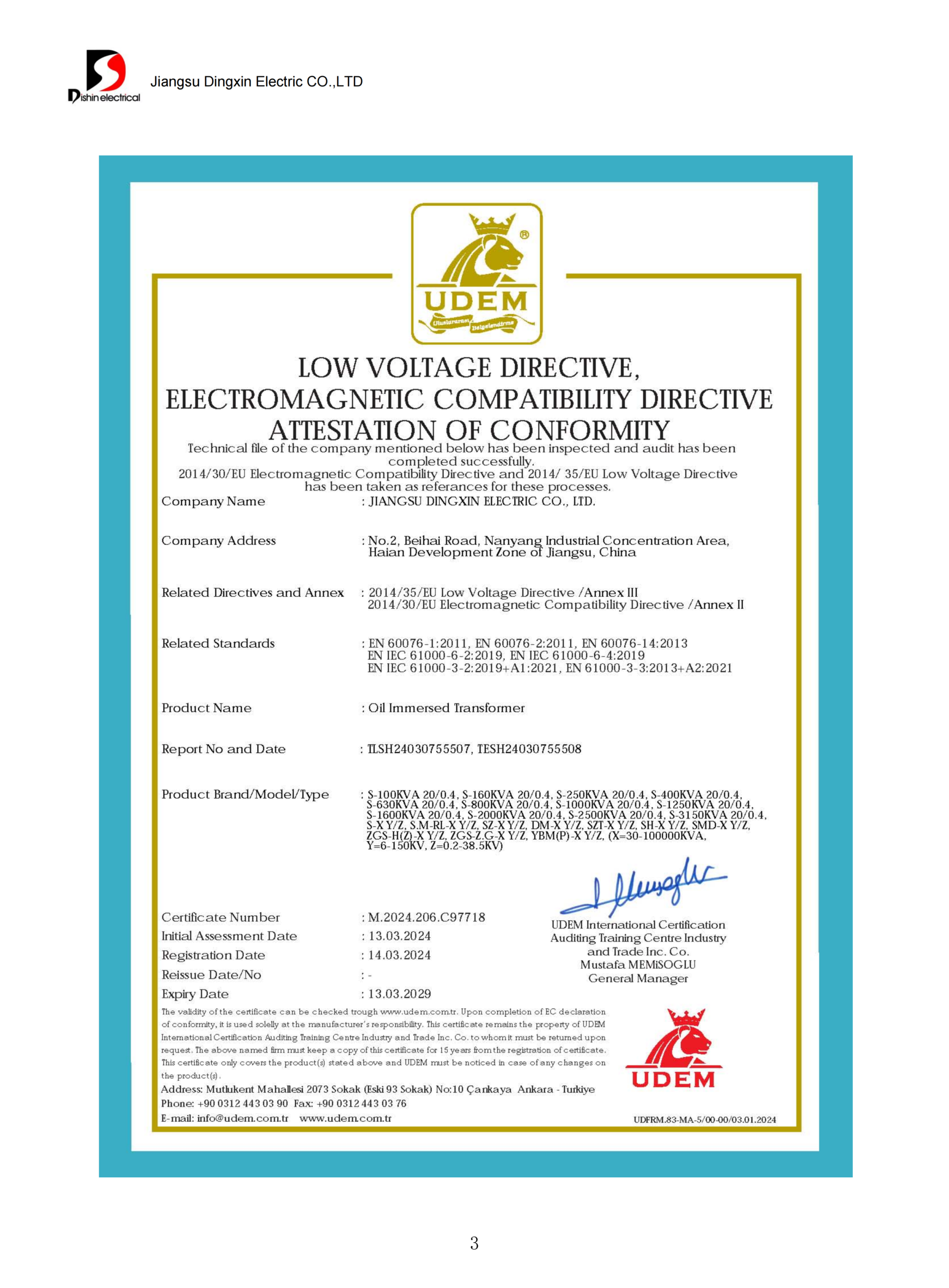
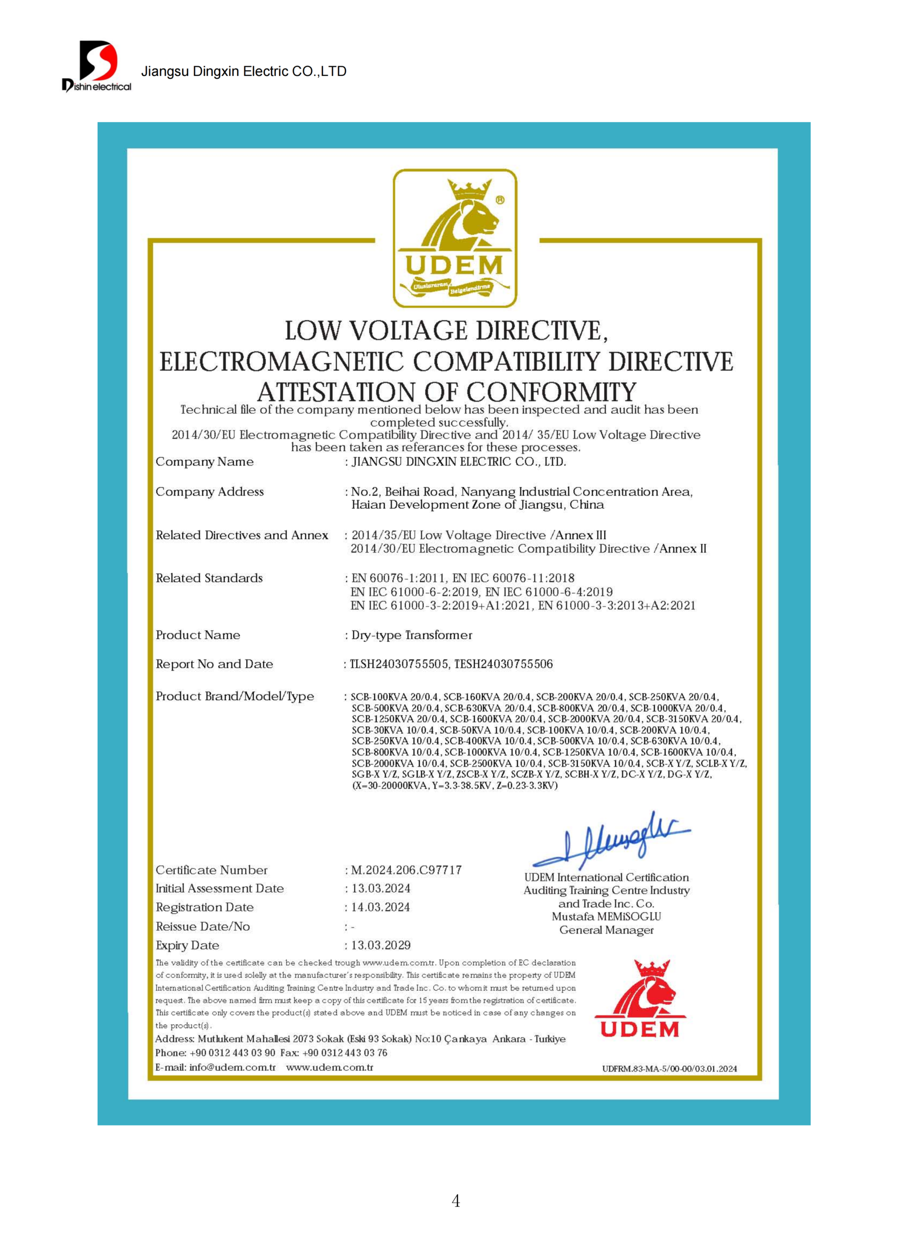
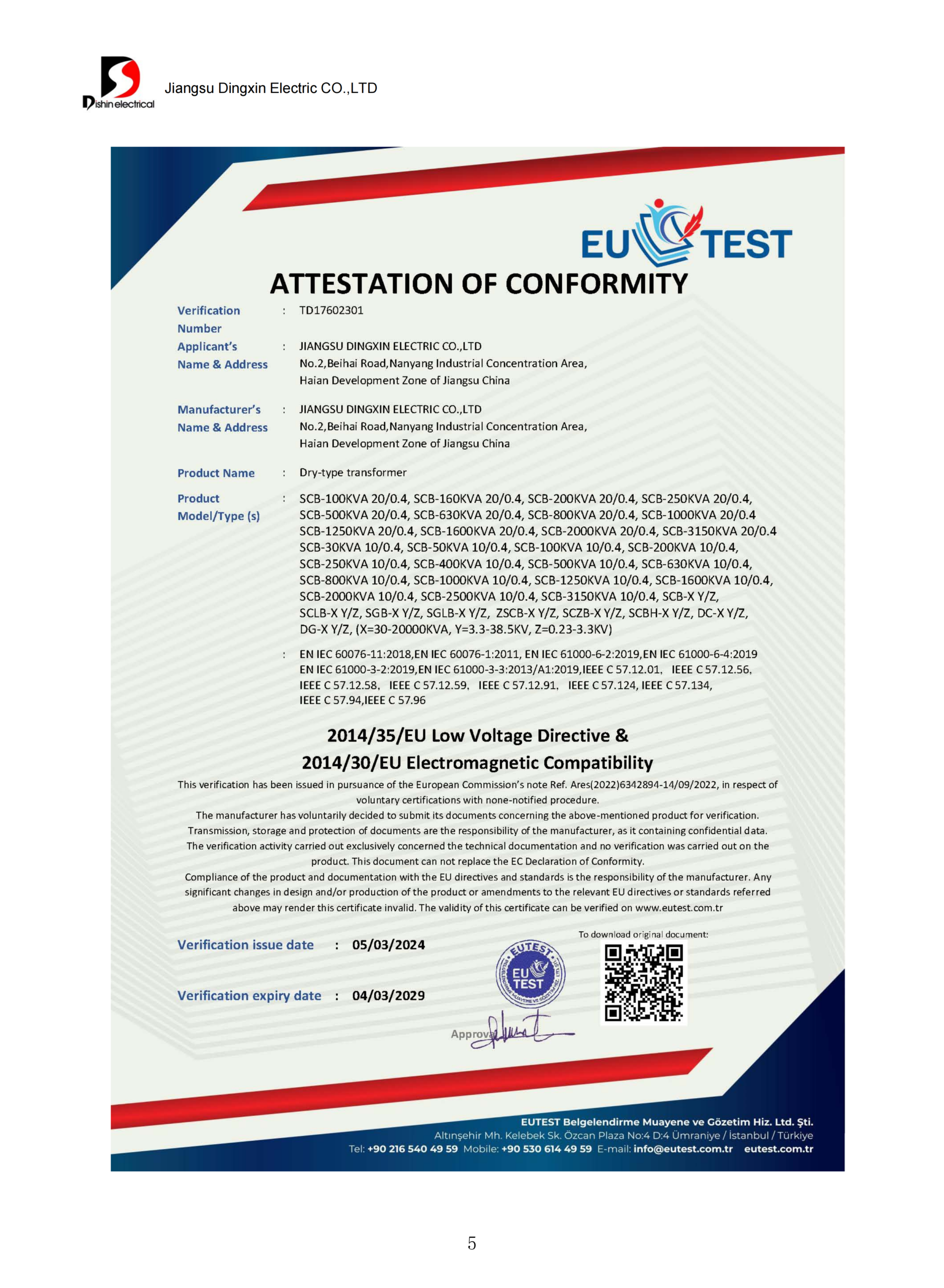
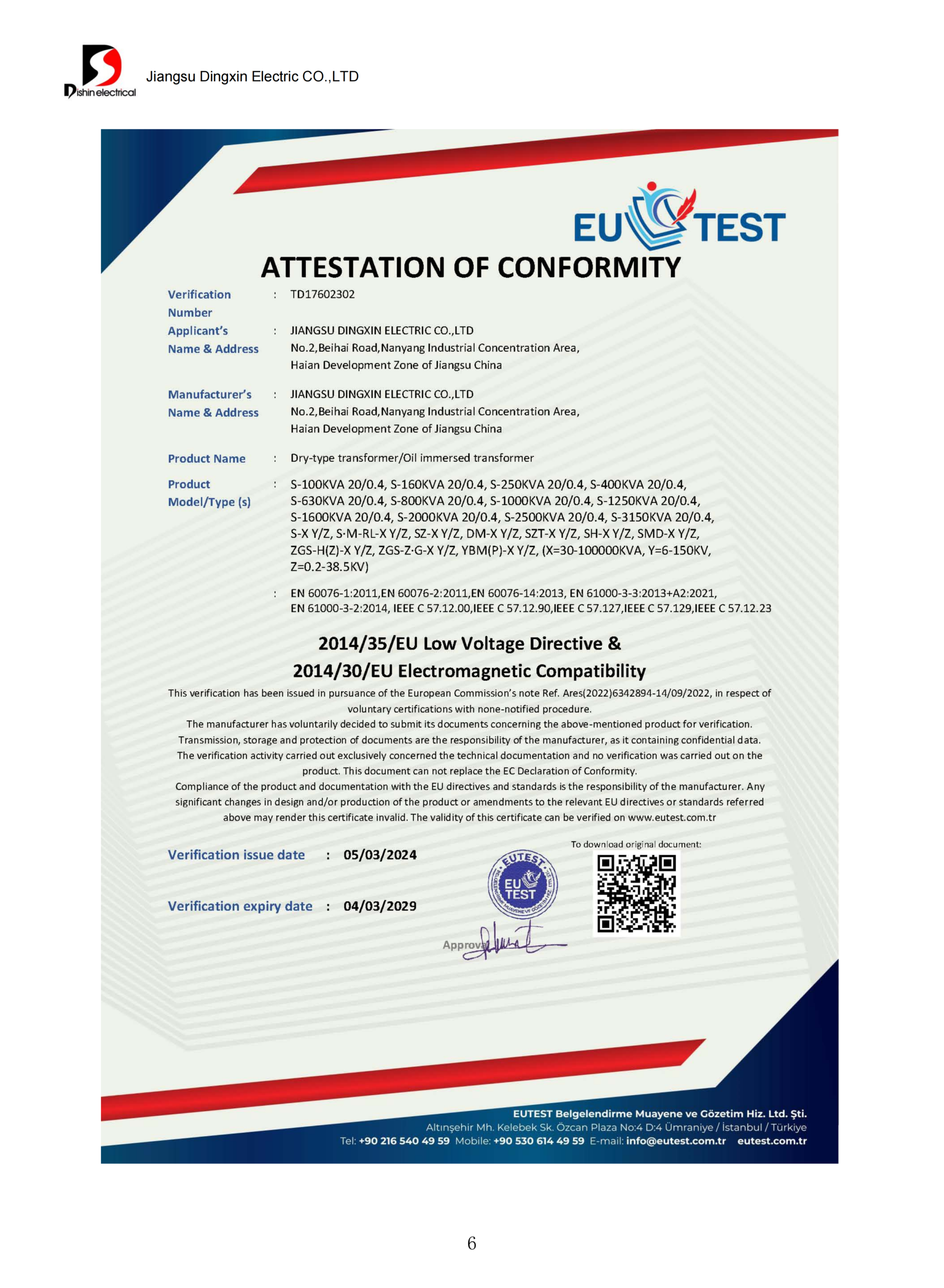
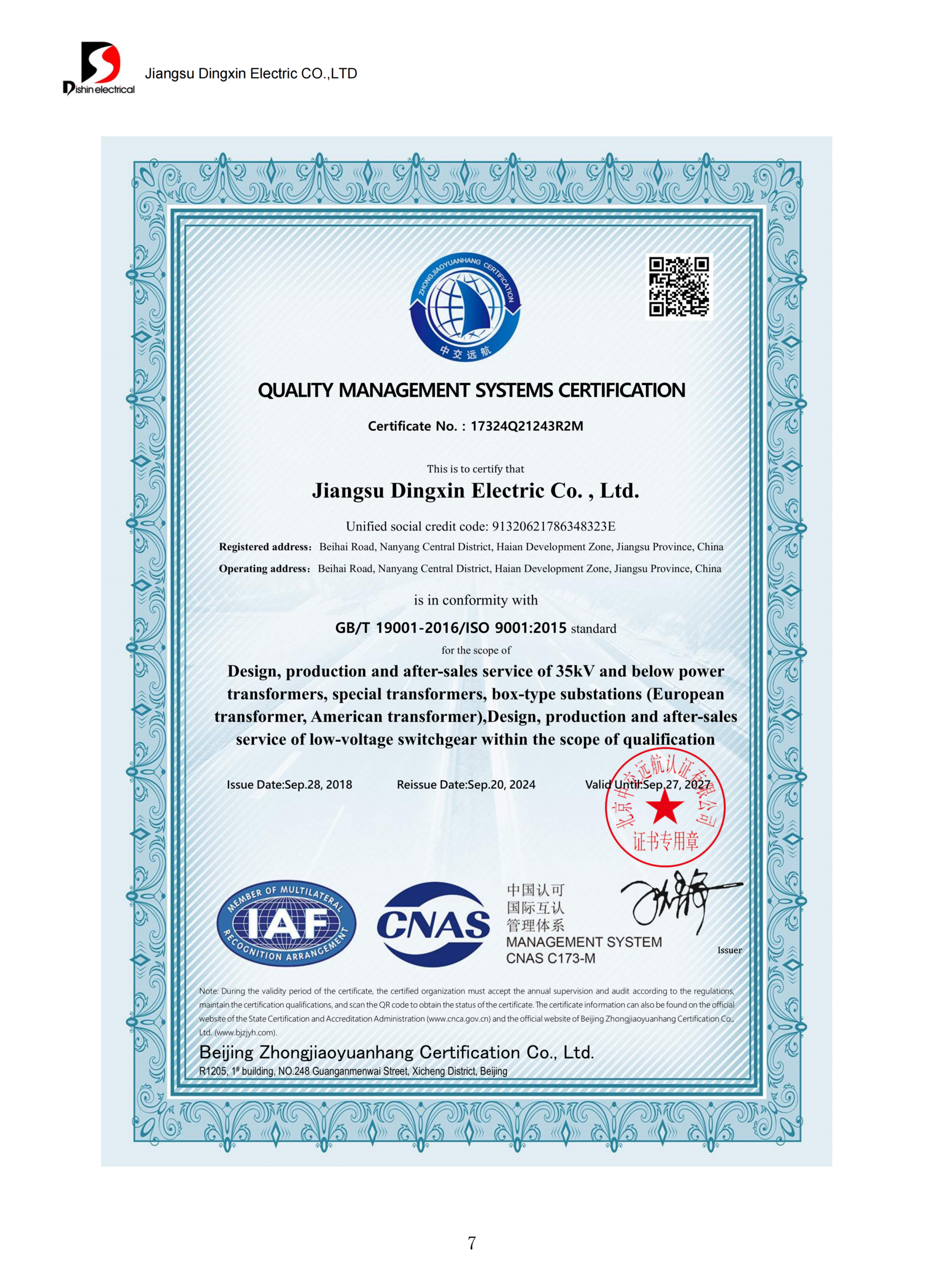
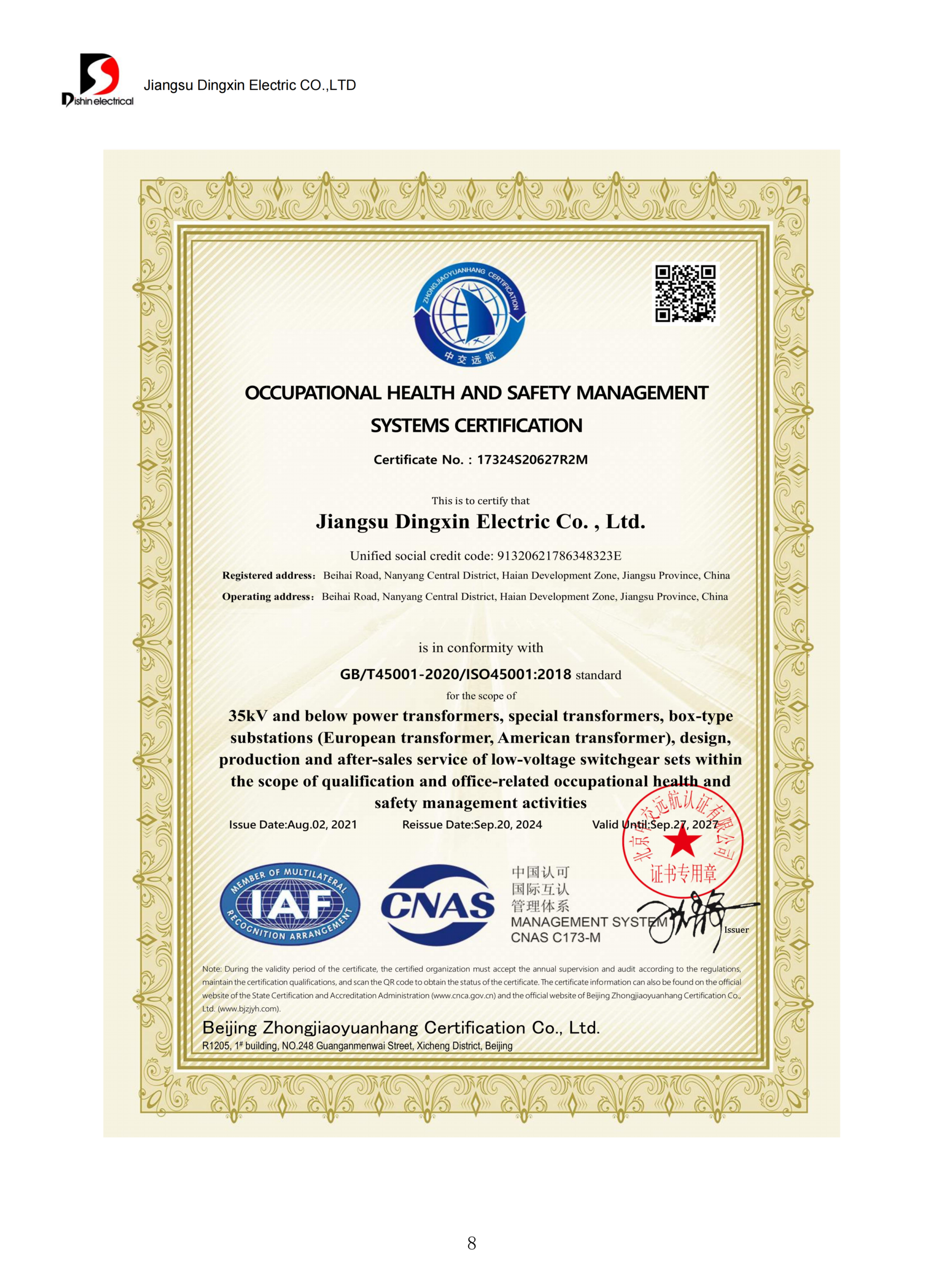
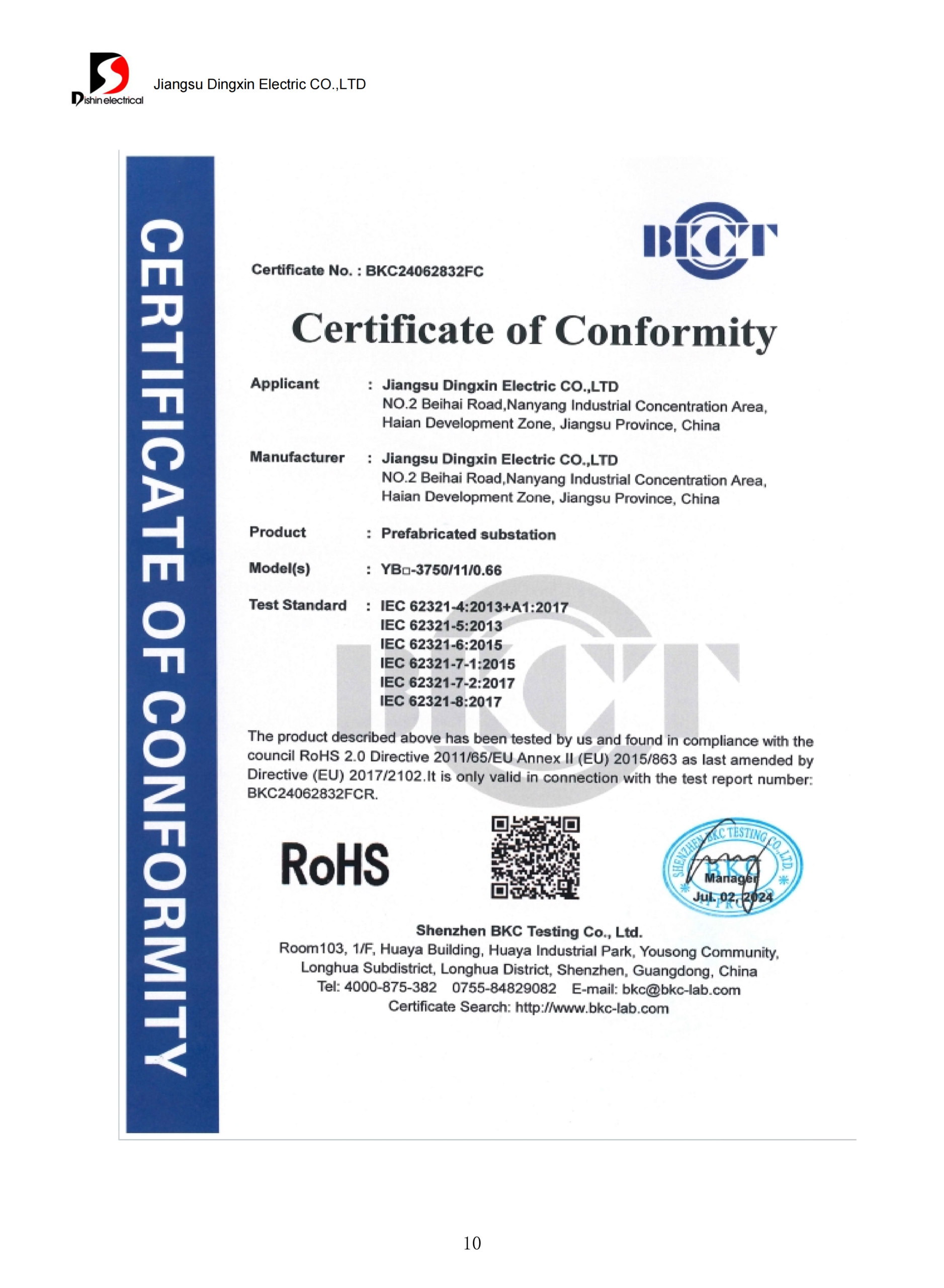
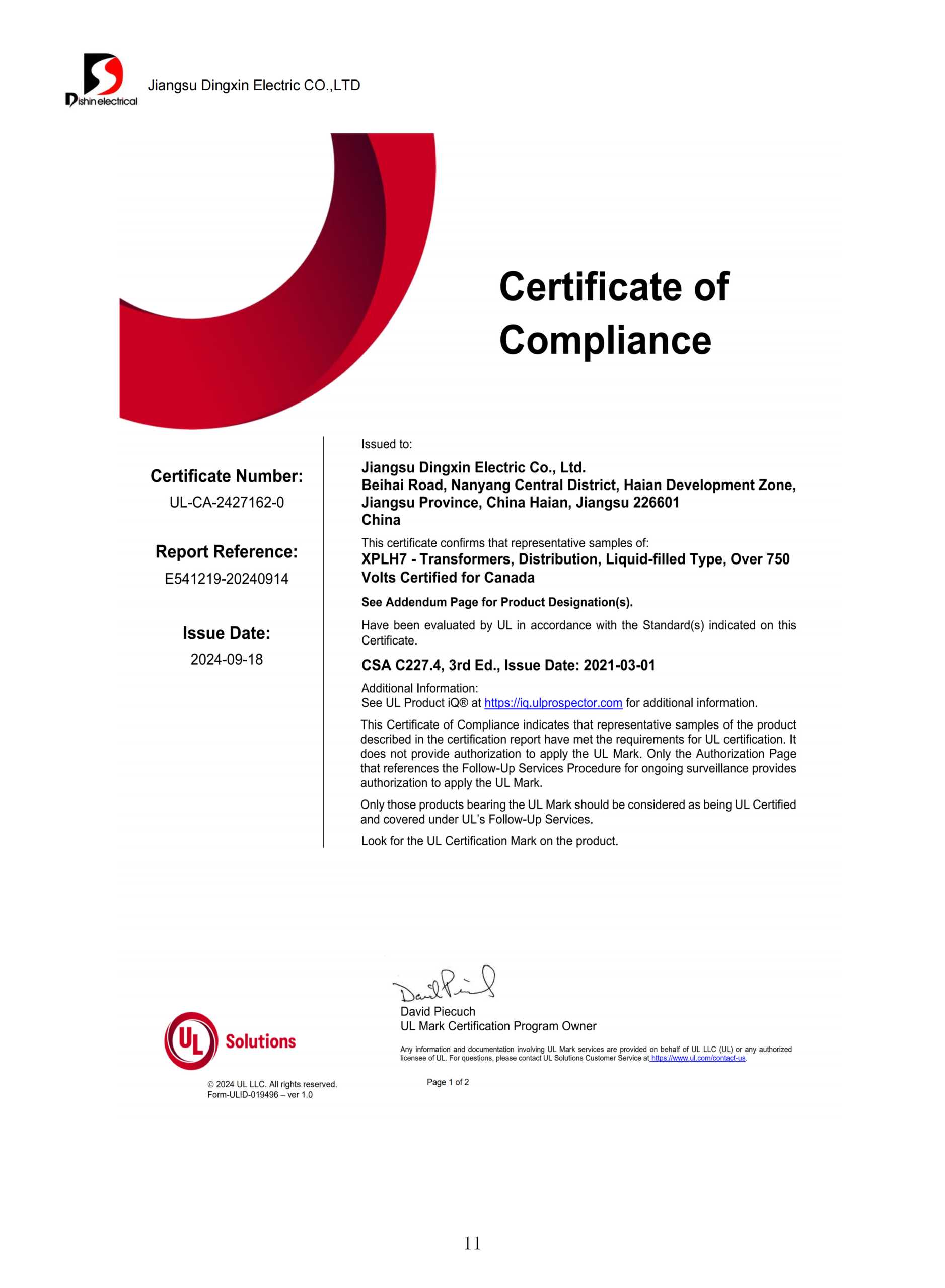
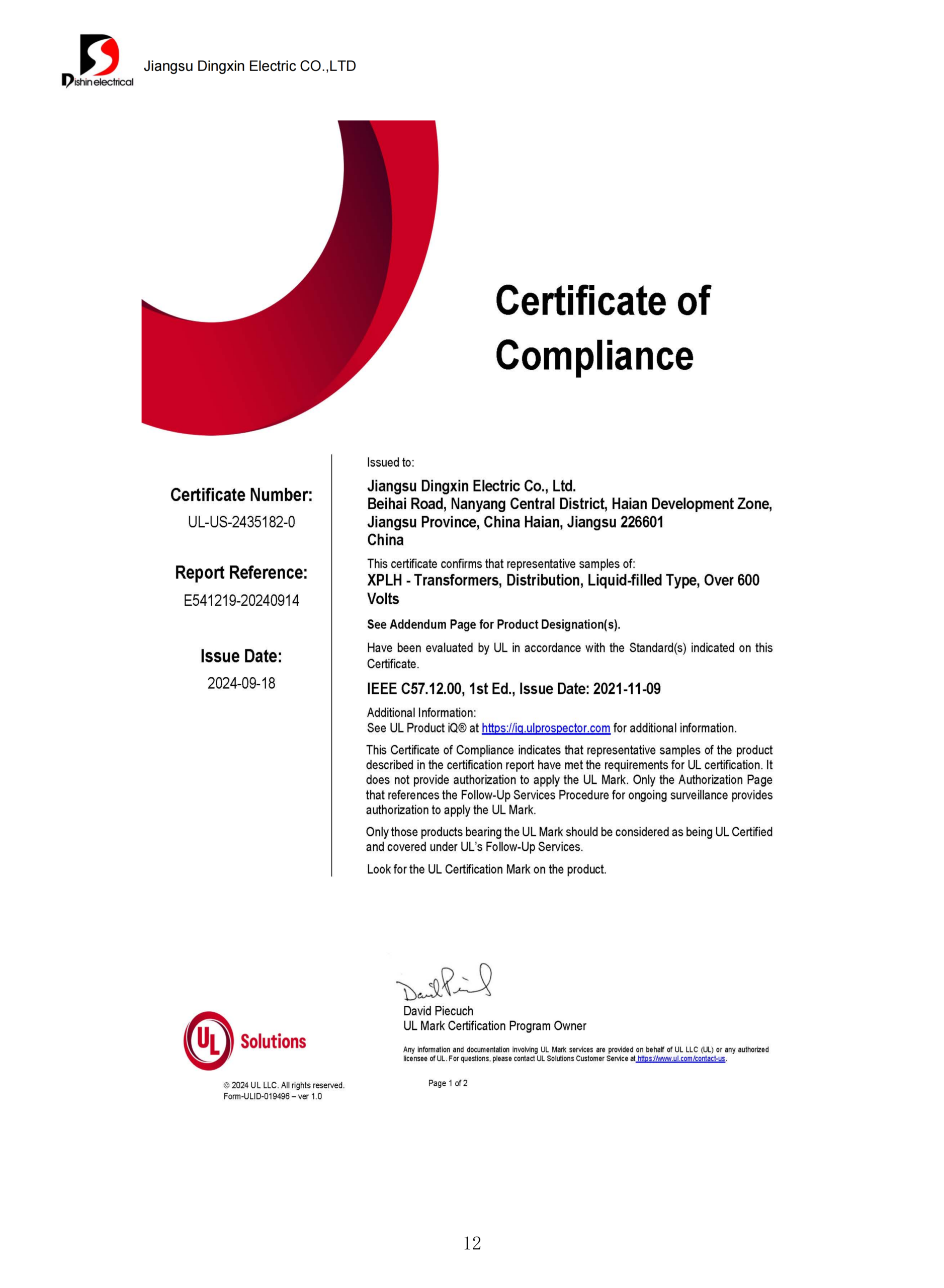
ISO Certified Quality

Oil-Immersed Transformer

Oil Immersed Transformers from 30 to 3,150 kVA

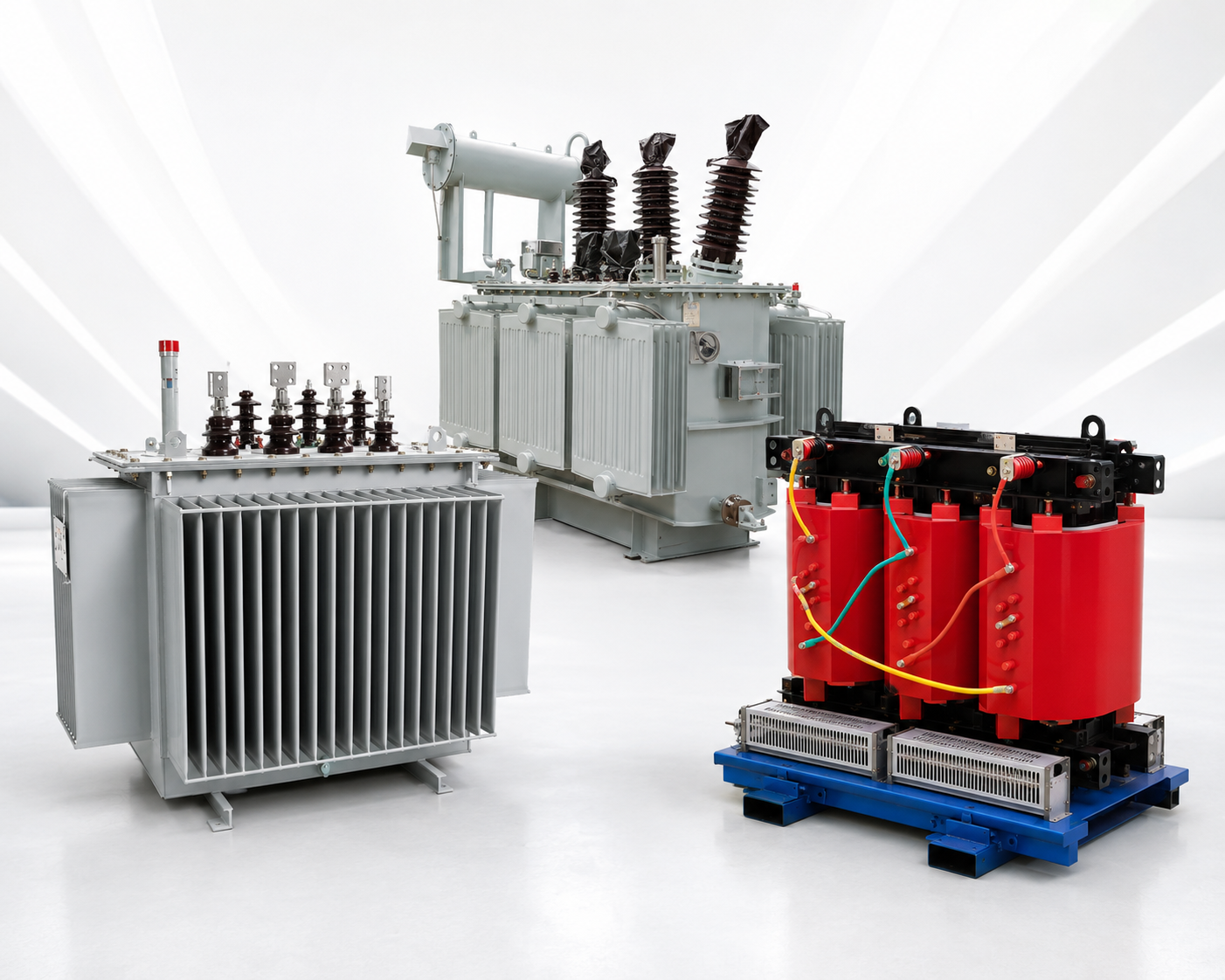
An oil immersed transformer places the core and winding assembly inside a tank of insulating liquid, so the same fluid does two jobs at once: it insulates the live parts and it carries heat away from them. The terms oil filled transformer and liquid filled transformer describe the same construction, and American specifications usually use the liquid-filled wording. Talite builds this construction from 30–3,150 kVA on the 6, 6.3 and 10 kV classes, and from 50 to 2,500 kVA on the 35 and 38.5 kV classes.

Send Your Electrical Schedule Your drawings, single-line diagrams and load schedules are handled as confidential.
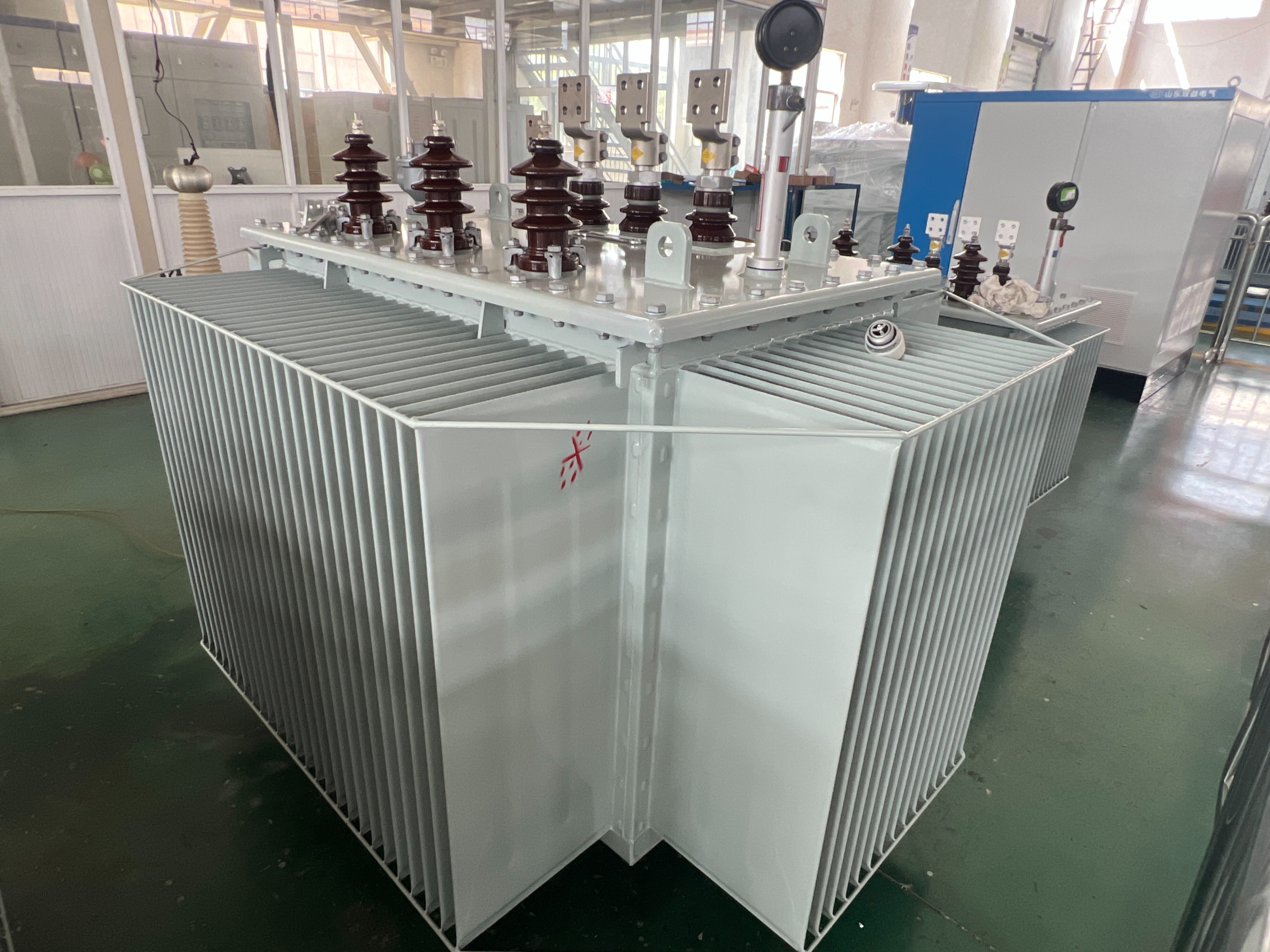
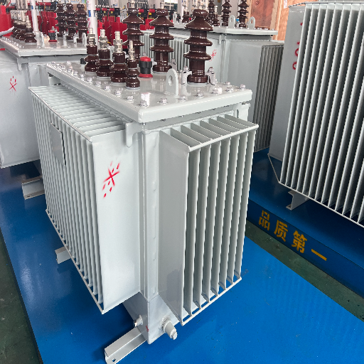
Oil-Immersed Transformer Side View
Oil-Immersed Transformer Front View

Engineer-reviewed quote within 24 hours

Standard ratings ship in 20–30 days

Single-unit orders accepted

Published loss and impedance schedule

Oil-Immersed Transformer Capability At A Glance

Published Rating Envelope

30–3,150 kVA at 6 / 6.3 / 10 kV, 0.4 kV secondary. 50 to 2,500 kVA at 35 / 38.5 kV.

Quotation Turnaround

We return an engineer-reviewed quotation within 24 hours on business days.

Standard-Rating Lead Time

Standard-rating units ship in 20–30 days after order confirmation and drawing approval. Freight is quoted separately.

Minimum Order

The minimum order quantity is one unit. We accept single-unit orders on standard ratings.

Trade Terms

EXW, FOB, CFR and CIF terms are standard. DAP and DDP delivery are quoted on request.

Warranty

The warranty period is 12 months from site acceptance, and no more than 18 months from dispatch, whichever comes first.

Buyers Write This Product Several Different Ways, And The Enquiries That Reach Us Use All Of Them.

What The Enquiry Says What It Means On This Page
Oil Immersed Type Transformer The same construction, named from a different specification tradition
Oil Filled Transformer, Dielectric Liquid Filled Transformer Also the same construction; the liquid-filled wording is the American habit
Oil Filled Distribution Transformers The same units described by their grid role rather than by their insulation, which is how most utility and contractor enquiries arrive
Three Phase Oil Immersed Transformer The three-phase member of the family, which covers almost every distribution order placed from this page
Oil Immersed Self Cooled Transformer Cooling by natural circulation with no fan and no pump, carrying the ONAN designation

Five Oil-Immersed Transformer Families and the Duty Each One Answers

Buyers arrive at this page with a kVA number and a voltage pair, not with a product name. Below, the Five-Family Duty Router turns those two inputs into the right page in one step. Each card answers the same five questions so the families can be compared side by side rather than read one at a time.

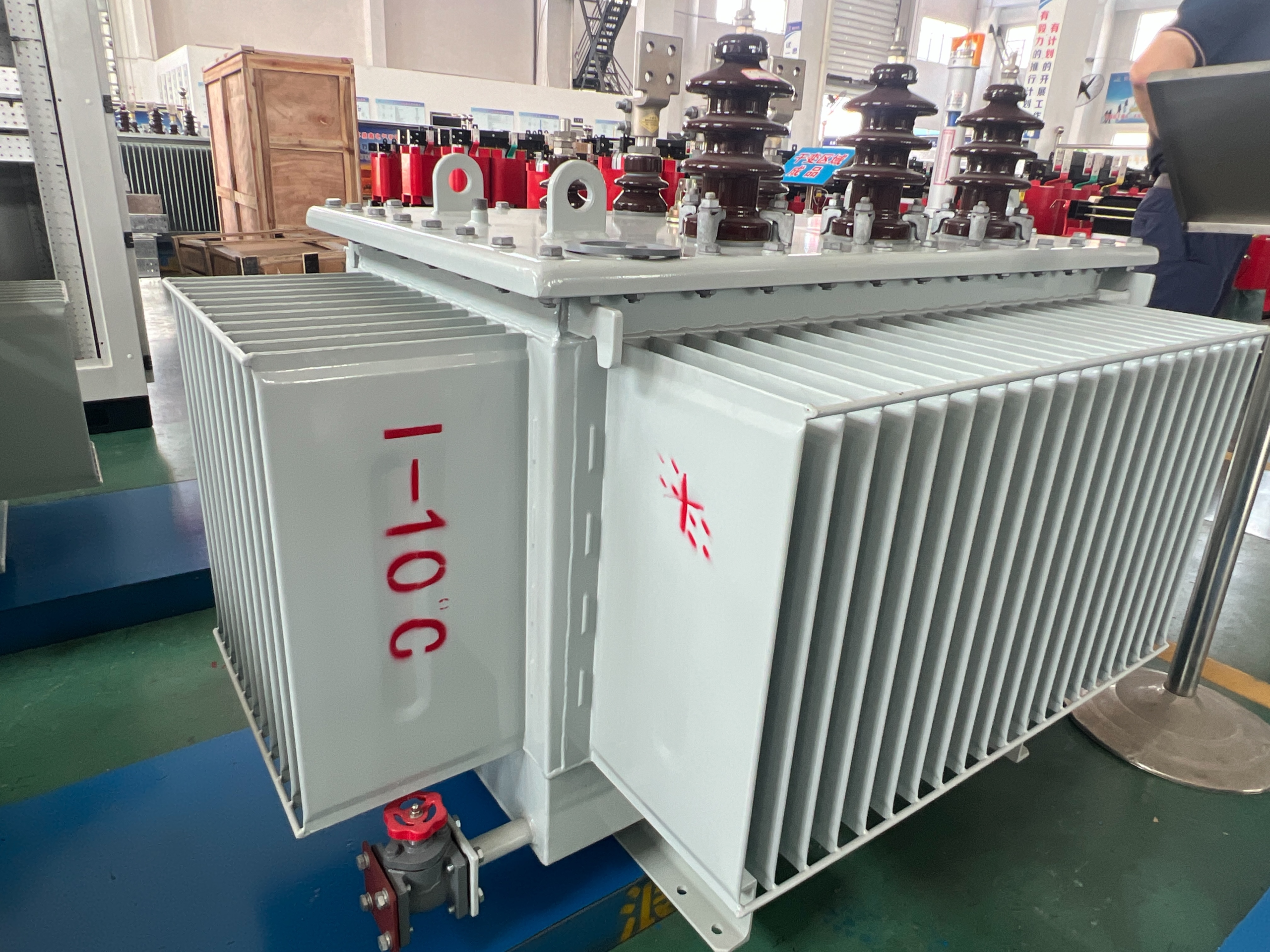
Sealed distribution transformers

Sealed distribution transformers

Duty Three-phase distribution from a 6, 6.3 or 10 kV network down to a 0.4 kV secondary. These are the oil filled distribution transformers most enquiries start from
Published band 30 kVA to 3,150 kVA
Mounting Indoor or outdoor, corrugated sealed tank, no conservator
Data published Full per-rating loss, impedance, mass and outline schedule
Higher-voltage project units

Higher-voltage project units

Duty 35 and 38.5 kV class supply into a project substation
Published band 50 kVA to 2,500 kVA on the published 35 kV schedule
Mounting Outdoor, three-phase tank with cooling surfaces
Data published Per-model loss and impedance schedule
Hermetically sealed units

Hermetically sealed units

Duty Sites where the fluid must stay isolated from the atmosphere
Published band The same 30 kVA to 3,150 kVA family, sealed configuration
Mounting Corrugated wall absorbs fluid expansion in place of a conservator
Data published Sealed-versus-conservator decision boundary
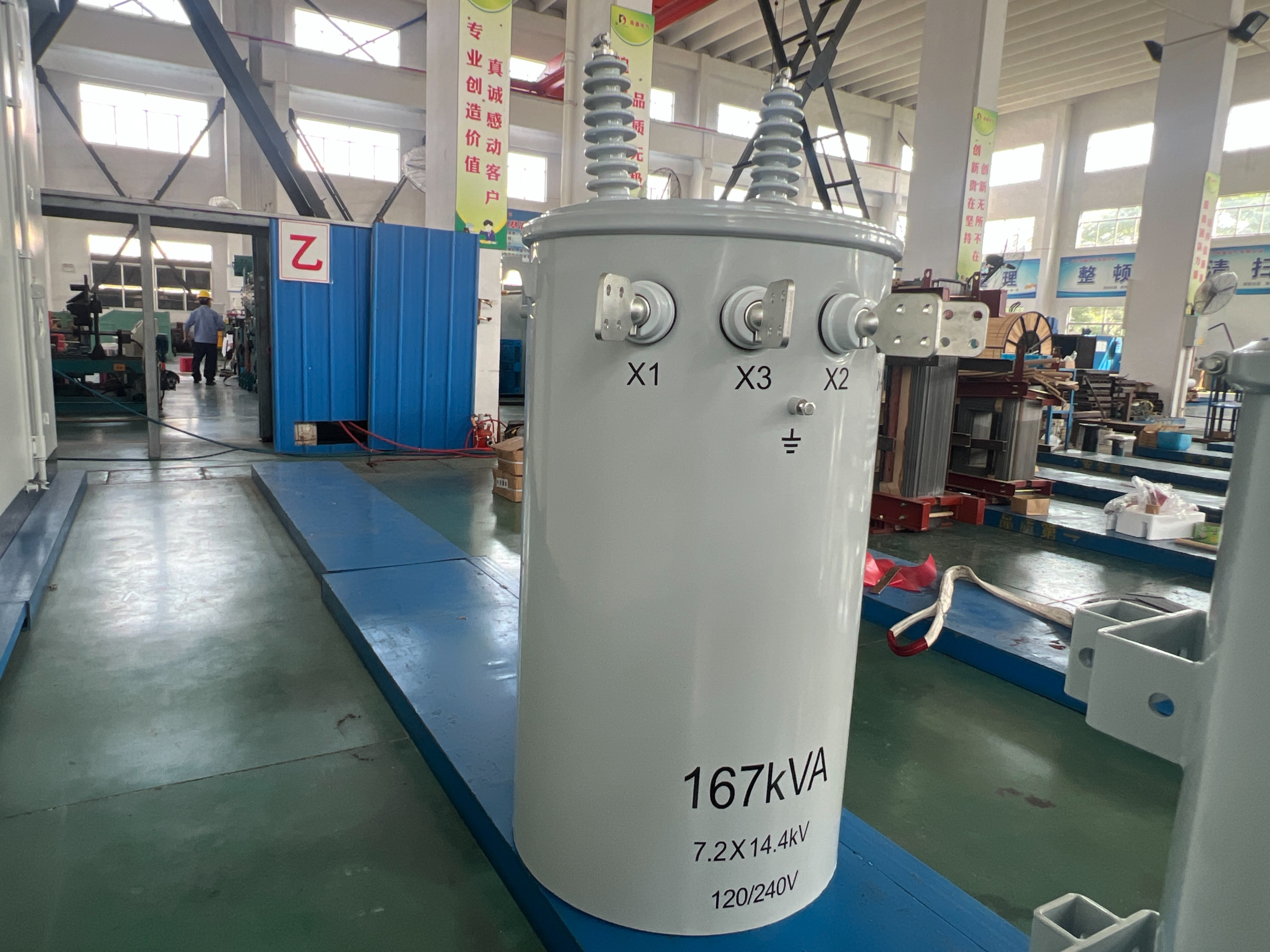
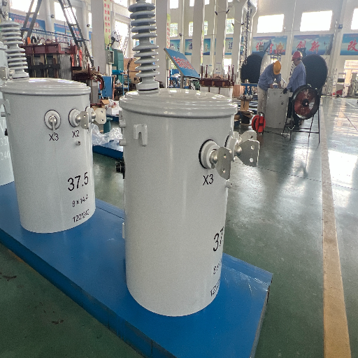
Single-phase vertical units

Single-phase vertical units

Duty Single-phase supply where no three-phase feed reaches the site
Published band Small ratings for rural, remote and distributed supply
Mounting Vertical tank; orientation and mounting are separate selection fields from the cooling method
Data published Mounting and interface fit check
Custom-engineered units

Custom-engineered units

Duty A voltage combination, vector group or impedance that no published row matches
Published band Defined by the project rather than by a catalogue row
Mounting Set by the site interface drawing
Data published The evidence register that has to close before release

Rating, Voltage and Vector Group Envelope for Oil-Immersed Transformers

Once the Five-Family Duty Router has narrowed the family, this section fixes the numbers inside it. You’re likely going to be sizing against a peak load the network operator has already fixed rather than against a number you are free to choose, because the operator wants the rating set as close to real peak load as the connection rules allow. That means the envelope below is a screening tool, and the binding numbers come from your electrical schedule.

Field Published value How it is fixed
Rated capacity, 10 kV class 30–3,150 kVA Selected from the published per-rating schedule
Rated capacity, 35 kV class 50 to 2,500 kVA Selected from the published 35 kV schedule
High voltage 6, 6.3 or 10 kV; 35 or 38.5 kV Stated in your enquiry
Low voltage 0.4 kV Stated in your enquiry
Vector group Yyn0 or Dyn11 Model dependent, confirmed on the data sheet
Tap range ±5% or ±2 × 2.5% Model dependent, confirmed on the data sheet
Rated frequency Confirmed per project Stated in your enquiry and fixed at drawing approval
Normal service conditions Altitude up to 1,000 m, ambient −25 °C to +40 °C From the supplied normal-service data
Rating, Voltage and Vector Group Envelope for Oil-Immersed Transformers

Why frequency sits on the enquiry, not on the nameplate promise

Frequency is the field that most often separates a specification written for one market from equipment built for another. It is also one of the five tests the United States uses to decide whether a unit is covered equipment at all. We fix it with you in writing before the design is released, and we do not treat it as a default.

Service conditions are the standard band, not a narrow one

Altitude up to 1,000 m and ambient −25 °C to +40 °C is the normal-service band published for this construction class, which is the band set out in IEC 60076-1, published in Europe as EN 60076-1

Conditions outside that band trigger an engineering review of the temperature-rise basis rather than an assumed derating factor

Humidity, contamination, coastal salt and seismic duty are separate inputs and are handled on the drawing, not by a footnote

Iron Core, Winding, Conservator and Radiator Construction

Ask about the oil immersed transformer working principle and the answer splits into two jobs the fluid does at once: it carries heat from the winding surfaces out to the tank wall, and it insulates between live parts at a dielectric strength air cannot reach across the same clearances. Core, windings, tank, fluid, oil filled transformer bushings and protection devices are the oil transformer parts that carry those two jobs out.
  • Core and windings generate the loss, and are where the heat has to leave from
  • Tank wall, corrugated panel or radiator bank is the surface that moves that heat into the surrounding air
  • Fluid, bushings, protection and monitoring devices are service items with an inspection interval, not fittings that are installed and forgotten

Our iron core is built from cold-rolled grain-oriented silicon steel with 45-degree fully mitred joints, which is the geometry that keeps the magnetic flux distribution even at the joints and holds no-load loss and magnetostrictive noise down. Low-voltage windings use copper foil in a cylindrical arrangement on all but the smallest ratings, and high-voltage windings use a multi-layer cylindrical structure so the ampere-turn distribution stays balanced and short-circuit strength stays high.

Two tank configurations, two accessory sets

Choosing between a hermetically sealed transformer vs conservator type construction is the question buyers raise most often, and site access to the fluid settles it rather than price.

Fully sealed corrugated tank

  • The corrugated wall flexes to absorb the volume change of the fluid as temperature moves, so no conservator is fitted and overall height drops
  • Because the fluid never meets outside air, oxygen and moisture ingress is removed as a degradation path
  • A pressure relief valve operating at 35 kPa releases pressure on an internal fault and reseats when pressure returns to normal

Conservator-equipped tank

  • An expansion vessel above the tank takes the fluid volume change instead of the corrugated wall
  • This is the configuration that carries a gas relay in the connecting pipework, which a fully sealed tank has no pipework for
  • Units of 800 kVA and above are fitted with a signal thermometer and a gas relay for temperature and fault alarms

Radiators are a third option rather than a default. Smooth-walled tanks with bolted-on radiators are used in some regions, and the choice between corrugated wall, radiator bank and conservator changes the footprint, the height and the accessory schedule, so it is confirmed on the order rather than assumed. Loss, temperature rise and the tolerances that apply to the figures in this section are defined by IEC 60076-1, published in Europe as EN 60076-1[3], which is also the document a bidder should be quoting its declared losses against.

Fluid and vacuum processing

  • Coils and core are vacuum dried, and the mineral oil is vacuum filtered and vacuum filled, which drives the residual moisture inside the unit to a minimum
  • The insulating fluid both cools and insulates, so its condition is a service parameter and not a fill-and-forget item
  • Fluid type and transformer oil grade are confirmed with the order; mineral oil is the standard fill, and alternative approved liquids are quoted on request against the grade your specification names

The corrugated wall is not a cost-saving shortcut. It removes the breather, the conservator and one external interface, and in exchange it fixes the fluid volume at the factory. That is a good trade for a sealed distribution unit and a poor one for a duty that needs field oil sampling, which is exactly why we ask which of the two you need before we draw anything.

— Talite Engineering Team

Oil-Immersed Transformer Loss, Impedance and Dimension Schedule

Two loss schedules are published for the 10 kV class: the S11-M sealed series and the S13-M energy-saving series. Subtracting one from the other rating by rating gives the S11-to-S13 Loss Delta Curve below, which is the number that decides operating cost rather than the number printed largest on a brochure.

S11-M Schedule
S13-M Schedule
Rated Capacity S11-M No-Load Loss S13-M No-Load Loss Difference Reduction
30 kVA100 W80 W20 W20.0%
50 kVA130 W100 W30 W23.1%
63 kVA140 W110 W30 W21.4%
80 kVA150 W130 W20 W13.3%
100 kVA200 W150 W50 W25.0%
125 kVA240 W170 W70 W29.2%
160 kVA290 W200 W90 W31.0%
200 kVA330 W240 W90 W27.3%
250 kVA400 W290 W110 W27.5%
315 kVA480 W340 W140 W29.2%
Rated Capacity S11-M No-Load Loss S13-M No-Load Loss Difference Reduction
400 kVA570 W410 W160 W28.1%
500 kVA680 W480 W200 W29.4%
630 kVA810 W570 W240 W29.6%
800 kVA980 W700 W280 W28.6%
1000 kVA1150 W830 W320 W27.8%
1250 kVA1360 W970 W390 W28.7%
1600 kVA1640 W1170 W470 W28.7%

What the S11-to-S13 Loss Delta Curve says that a headline percentage does not

No-load loss reduction from S11-M to S13-M at each rating, computed from the two schedules in the table above. The dashed red line is the 30% figure the category markets on; the dotted black line is what these two schedules actually average. Sixteen of the seventeen ratings sit below the red line.

  • Across the seventeen ratings both schedules share, the reduction averages 26.3% and spans 13.3% to 31.0%
  • Only one rating, 160 kVA, clears 30%, so a single round figure would misdescribe sixteen of the seventeen rows
  • The 80 kVA row is the weakest at 13.3%, and a buyer sizing at 80 kVA should know that before paying an energy-saving premium
  • No-load loss is incident to excitation, so it runs for all 8,760 hours a year whether or not the unit is carrying load
  • That last point is why the delta curve matters more than it looks. Load loss varies with loading and a distribution unit is rarely at full load, so on a lightly loaded feeder the no-load column is the one that dominates lifetime energy cost. The total owning cost method used in utility procurement handles this by capitalising the two loss categories separately before comparing bids.

The 800 kVA Impedance Threshold

Short-circuit impedance in the published S11-M schedule steps from 4.0% to 4.5% at 630 kVA. United States rules draw their own line in a different place, and the two are often confused.

Rating Band Published Impedance Federal Normal Range, Three-Phase Liquid-Immersed Position
30 to 63 kVA4.0%1.0–4.5% for 15 ≤ kVA < 75Inside the range
80 to 100 kVA4.0%1.0–5.0% for 75 ≤ kVA < 112.5Inside the range
125 to 400 kVA4.0%1.2–6.0% for 112.5 ≤ kVA < 500Inside the range
500 to 630 kVA4.0–4.5%1.5–7.0% for 500 ≤ kVA < 750Inside the range
800 to 3,150 kVA4.5%5.0–7.5% for 750 ≤ kVA ≤ 5000Below the lower bound
  • The 800 kVA Impedance Threshold is where the federal band floor rises to 5.0% while the published impedance stays at 4.5%
  • A transformer built to operate outside the normal impedance range for its rating meets the special-impedance definition, and special-impedance transformers are one of the thirteen types excluded from the federal distribution-transformer definition[1]
  • If your specification needs covered equipment at 800 kVA or above, the impedance has to be designed into the 5.0–7.5% band, which is a design change and not a selection option
  • Below 750 kVA the published impedance sits inside the normal range, so impedance is not what decides coverage there
  • Reading that table as a compliance conclusion would be a mistake, because impedance is only one of five tests. Input voltage, output voltage, frequency, capacity and impedance all have to be assessed together against the definition, and frequency is the field we confirm with you rather than assume.

Oil mass and the site containment threshold

The published schedule gives oil mass for every rating, and that number feeds a calculation most transformer pages never mention. United States facilities count qualifying oil-filled equipment toward their aggregate aboveground oil capacity, and only containers of 55 gallons or more are counted at all.[2]

Rated Capacity Oil Mass Approximate Volume Counts Toward The 55-Gallon Threshold
100 kVA115 kgabout 35 US gallonsNo
200 kVA170 kgabout 52 US gallonsNo
250 kVA190 kgabout 58 US gallonsYes, first rating to cross
630 kVA320 kgabout 98 US gallonsYes
1000 kVA570 kgabout 175 US gallonsYes
1600 kVA750 kgabout 230 US gallonsYes
3150 kVA1180 kgabout 362 US gallonsYes
  • Volumes are screening estimates converted at a fluid density of 0.86 kg per litre; the delivered fluid data sheet gives the density that applies to your order
  • 250 kVA is the first published rating whose fluid charge crosses the 55-gallon counting line
  • Four 3,150 kVA units hold roughly 1,450 gallons between them, which is above the 1,320-gallon aggregate figure on its own
  • This is a screening calculation for the design team, not a compliance determination, which belongs to the facility owner
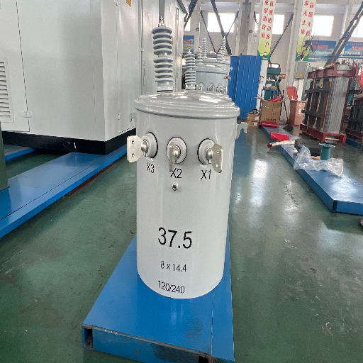
SYS.ON // 8x14.4 - 120/240
37.5
ID: X1-X2-X3 // CAP: 37.5 KVA

Price Mechanism, Lead Time and Trade Terms

Price Mechanism

Price follows the electrical design, the accessory schedule, the test and document scope, the quantity and the delivery terms rather than a fixed price list. Two quotations for the same kVA number are not comparable until both state the same loss basis, the same impedance, the same conductor material and the same test scope.

What has to match before two quotations can be compared

  • Rated capacity, both voltages, frequency, phase and vector group
  • Guaranteed no-load loss and load loss, each with the reference temperature they are corrected to and the tolerance they carry
  • Short-circuit impedance and the tap range it applies at
  • Conductor material, since copper and aluminium windings are different products even where the rating matches
  • Accessory schedule, protection devices and monitoring
  • Test scope, witness points and which reports ship with the unit
  • Packing, trade term and destination, because the delivery point moves a large share of the landed cost

Losses are declared values corrected to a reference temperature, and a declared value carries a permitted tolerance under the governing standard.[3] Ask every bidder to state the reference temperature and the tolerance alongside the watts. Without those two fields the loss columns in two offers are not measuring the same thing.

Lead Time

Lead time, stated with its boundaries

Lead times are the first thing most buyers ask about and the last thing most category pages answer. Ours carry their boundary conditions below, because a date without a boundary is not a commitment.

  • Standard-rating units ship in 20–30 days after order confirmation and drawing approval. Surface finishing and transit time are quoted separately
  • Production lead times for custom-engineered and higher-voltage-class units are confirmed with your quotation, based on rating, voltage class, test scope and quantity
  • Expedited scheduling is reviewed case by case and confirmed with the quotation

For context on why this matters: Wood Mackenzie put average transformer lead times at around 120 weeks in 2024, against around 50 weeks in 2021, and large substation and generator step-up units at 80 to 210 weeks

Those figures were published in April 2024, cover the whole transformer market and are weighted by large units, so read them as market backdrop rather than as a like-for-like comparison with a standard-rating distribution unit, and check the current position before you plan against them. They do explain why delivery certainty now outranks headline price in most enquiries we receive.

Commercial terms

We work on telegraphic transfer terms: 30–50% deposit with the order, balance settled before dispatch. Letters of credit are accepted on large orders

EXW, FOB, CFR and CIF terms are standard. DAP and DDP delivery are quoted on request

The minimum order quantity is one unit, and single-unit orders on standard ratings are accepted

Commercial invoice, packing list, bill of lading, certificate of origin and the routine test report are supplied with your shipment. A safety data sheet for the insulating fluid is issued where the destination requires it

Routine Testing and the Document Pack That Ships With the Order

Executive Overview

Transformer fit-and-finish are the easiest things to judge from a photograph and among the least common reasons a supplier loses a framework position. Test evidence and delivery logistics are what remove suppliers from bid lists, sometimes for years at a time, so this section leads with what you receive rather than with what we claim.

Tests Performed Before Dispatch

  • Voltage ratio, polarity and phase relationship on each tapping
  • Winding resistance on all windings
  • No-load loss and no-load current measurement
  • Load loss measurement at rated current and frequency
  • Impedance voltage measurement
  • Induced overvoltage and separate-source voltage withstand
  • Oil leak check on the completed tank

Factory acceptance testing, type testing and third-party inspection are available on request, and witness attendance is arranged with the order rather than negotiated after the unit is built. Acceptance criteria are written into the approved data sheet before production starts, so a disagreement about whether a result passes has a document to settle it.

What a Long Service Life Actually Asks of the Owner

If you treat an oil-immersed unit as a serviceable asset, with fluid condition checked on a schedule, bushings and protection devices inspected and alarms acted on, service life is counted in decades. Treated as sealed-and-forgotten equipment, the fluid becomes the first thing to fail. That is why the document pack carries the service parameters and not only the pass or fail lines.

Who Certifies What, and When It Is Confirmed

For equipment covered by United States energy-conservation standards, the obligation to certify compliance sits with the manufacturer or the importer of record, not with the specifying engineer. That obligation is a market fact rather than a product feature, and which party carries it on your order is settled in the contract. We identify the applicable route with you during the technical review.

The Five Tests That Decide United States Coverage

Test Federal Criterion Where the Answer Comes From
Input line voltage 34.5 kV or less Your network voltage
Output line voltage 600 V or less Your secondary voltage
Frequency Operation at 60 Hz Confirmed in writing before design release
Capacity, liquid-immersed 10 kVA to 5000 kVA The rating you select
Excluded types Thirteen named types, including special-impedance units The 800 kVA Impedance Threshold table above

All five tests have to be satisfied together, and a unit that fails any one of them is outside the covered category rather than non-compliant within it.[1] The screening tool below runs the same five questions so you can check a rating before writing it into a specification.

Check covered-transformer scope against 10 CFR 431.192 or open the impedance category screen for a single rating.

Talite operates from a site of 25,000 square metres with 260 production and test machines and a technical team of more than 30 engineers, and has supplied power equipment for over three decades.

×
Enlarged View

Industries We Supply: Utility Grid, Industrial Power Distribution, Renewable and Infrastructure

Utility Distribution Networks

Inputs

Network voltage, load profile, loss valuation factors, utility specification, batch quantity

Evidence

Model schedule, approved drawings, test scope, guaranteed loss values

Risk

An overhead or pad-mounted class may govern the project instead of this one

Industrial Power Distribution

Inputs

Motor loads, harmonic content, fault level, ambient, downtime consequence

Evidence

Electrical schedule, accessory list, acceptance criteria

Risk

Nonlinear current adds harmonic heating that nameplate losses do not describe

Renewable Energy Generation and Storage

Inputs

Inverter interface, voltage range, harmonics, generation profile, grid-connection study

Evidence

Grid study and an agreed electrical and test scope

Risk

A renewable energy label on the project never establishes power capacity or model fit on its own

Infrastructure and Data Centres

Inputs

Footprint, sound level, cable interfaces, redundancy, access, oil volume and containment

Evidence

Outline drawing, cable arrangement, protection review

Risk

Room, fire and continuity constraints can change the transformer type entirely

Two duty inputs cut across all four classes and are the ones most often left out of an enquiry: the loading profile the unit will actually see, and the fluid volume the site has to contain. The first decides which loss column dominates the energy bill, and the second decides whether the installation drags civil and environmental work behind it.

Where a Dry-Type or Pad-Mounted Unit Is the Better Answer

An oil immersed transformer is the wrong answer on several kinds of site, and saying so early is cheaper for both of us than discovering it at drawing approval. An oil filled transformer vs dry type comparison is rarely settled on electrical performance; the room, the fire rules and the fluid settle it, and those three sit outside the electrical specification entirely.

Indoors, an oil-insulated transformer has to sit in a vault, and which OSHA standard applies changes how absolute that is. Under the general industry rule the requirement is flat: oil-insulated transformers installed indoors shall be installed in a vault. Under the construction rule it applies where they present a fire hazard to employees. Either way the vault has to contain fire and combustible liquids, exclude unauthorised access, carry no foreign pipe or duct and store no materials. Unlike a dry-type installation, that vault is civil work with its own cost and its own critical path.

Where combustible material, combustible buildings, fire escapes or door and window openings sit next to the unit, they have to be safeguarded from fires that may originate in an oil-insulated transformer attached to or adjacent to them. Both standards carry that one in the same words.

Above 1,000 m altitude, or outside the −25 °C to +40 °C normal-service band, the temperature-rise basis is reviewed before a rating is fixed, because an assumed derating factor is a guess wearing a number.

Near navigable water the fluid volume counts toward the site aggregate. A transformer is oil-filled operational equipment in the federal definition and not a bulk storage container, which changes how it is regulated but not whether its oil counts: at a screening density the 250 kVA rating already passes 55 US gallons, and four 3,150 kVA units land near 1,450 gallons. Containment can then cost more than the difference between the two technologies, and that risk lands on the civil budget rather than the electrical one.

In North American pad-mount practice, compartmental construction is a separate equipment class with its own interface standards, and this page is not a substitute for it.

What a sealed oil-filled unit buys you is power density, overload behaviour and a lower purchase price for the same kVA. What it costs you, on the wrong site, is a vault, a containment structure and a fire-protection review signed off by people who never read the electrical specification, and that is the trade-off in one line. It is worth an hour with a procurement engineer and the site inspector before the order rather than a month after it.

Talite quotes both technologies, which is why we can say this

Getting the right call here does not cost Talite the order. Where the boundary shifts, a dry-type unit is the correct answer and we will say so, in writing, before the order rather than after the vault drawing comes back.

Oil-Immersed Transformer Assessment Tools

Loss Delta and Annual Energy Lookup

Compares the published no-load loss of the S11-M sealed series against the S13-M energy-saving series at the same rating, then converts the difference into annual energy and cost at your own tariff. No-load loss runs whenever the unit is energised, so the hours field defaults to a full year.

Impedance Category Screen

Checks a rating and its short-circuit impedance against the normal impedance ranges published in 10 CFR 431.192 for liquid-immersed transformers. A unit built to operate outside the normal range for its rating meets the special-impedance definition, which is one of the thirteen types excluded from the federal distribution-transformer category.

Oil Volume Containment Screen

Converts the published oil mass of a rating into volume and checks it against two United States thresholds in 40 CFR 112: a container is counted only when it holds 55 US gallons or more, and a facility whose aggregate aboveground capacity stays at or below 1,320 US gallons can meet the exemption on that criterion. Federal definitions treat a transformer as oil-filled operational equipment rather than as a bulk storage container, so the provisions that apply to it differ from tank rules even though the volume still counts. This is a design-team screening aid, not a compliance determination.

RFQ Input Completeness Check

Scores an enquiry against the fields that have to be present before two quotations can be compared on the same basis. Fields marked critical are the ones that change the design rather than the paperwork.

FAQ on Oil Immersed Transformer Selection, Loss Comparison and Coverage

It is a transformer whose core and winding assembly sits in a tank of insulating liquid, so the fluid provides both dielectric insulation and heat transfer. Buyers also call it an oil filled transformer, or a liquid filled transformer in American specifications.

Liquid-filled transformers move heat into a fluid and then out through the tank surfaces, which supports higher power density and stronger overload behaviour. A dry-type unit uses solid insulation and air. Fire rules, enclosure, footprint, containment and load duty decide which one belongs on a given site.

Compare the guaranteed value, at the same reference temperature, with the tolerance stated. Declared losses are corrected to a reference temperature, and a figure quoted without that basis cannot be set against another supplier's figure.

No. No-load loss is incident to excitation and runs whenever the unit is energised, while load loss varies with loading. On a lightly loaded feeder the no-load column typically dominates lifetime energy cost, which is why the S11-to-S13 Loss Delta Curve on this page compares that column first.

It is a design band in the published schedule, stepping from 4.0% to 4.5%. It is a separate matter from the United States normal impedance range, which changes at 750 kVA for three-phase liquid-immersed units.

That is settled per project against five criteria: input voltage, output voltage, frequency, capacity and whether the unit falls into one of the thirteen excluded types. The 800 kVA Impedance Threshold is the one to check first: at 800 kVA and above the published 4.5% impedance sits below the federal normal range, which brings the special-impedance exclusion into play.

No. Fluid condition, bushings, protection devices, leakage risk and inspection scope all remain service items. A sealed tank removes one external interface; it does not remove the service plan.

Frequency is confirmed per project and fixed in writing before design release. It is stated in your enquiry rather than assumed, because it is one of the five criteria that decide United States coverage and because network standards differ by market.

Oil mass is published for every rating on the schedule, from 70 kg at 30 kVA to 1,180 kg at 3,150 kVA. Converted at a screening density, 250 kVA is the first rating whose fluid charge crosses 55 US gallons, which is the threshold at which a container is counted toward a United States facility's aggregate oil capacity. Federal definitions treat a transformer as oil-filled operational equipment rather than as a bulk storage container, so the applicable provisions differ even though the volume still counts.

Commercial invoice, packing list, bill of lading, certificate of origin and the routine test report are supplied with your shipment, with a fluid safety data sheet where the destination requires it. Additional test or type-test evidence is agreed in the contract before production.