Get in touch with Toplit Transformer Co., Ltd Company

Hermetically Sealed Transformers for Distribution Networks | Talite
A hermetically sealed transformer confines insulating oil within a closed tank while corrugated walls accommodate temperature-driven volume change. Talite engineers configure the electrical ratings, accessories, tests, and documents around the application, destination, and installation conditions.
Process & Delivery Scope
Evidence-led offer
Data sheet, drawings, tests, and deviations by agreed scope
Destination screen
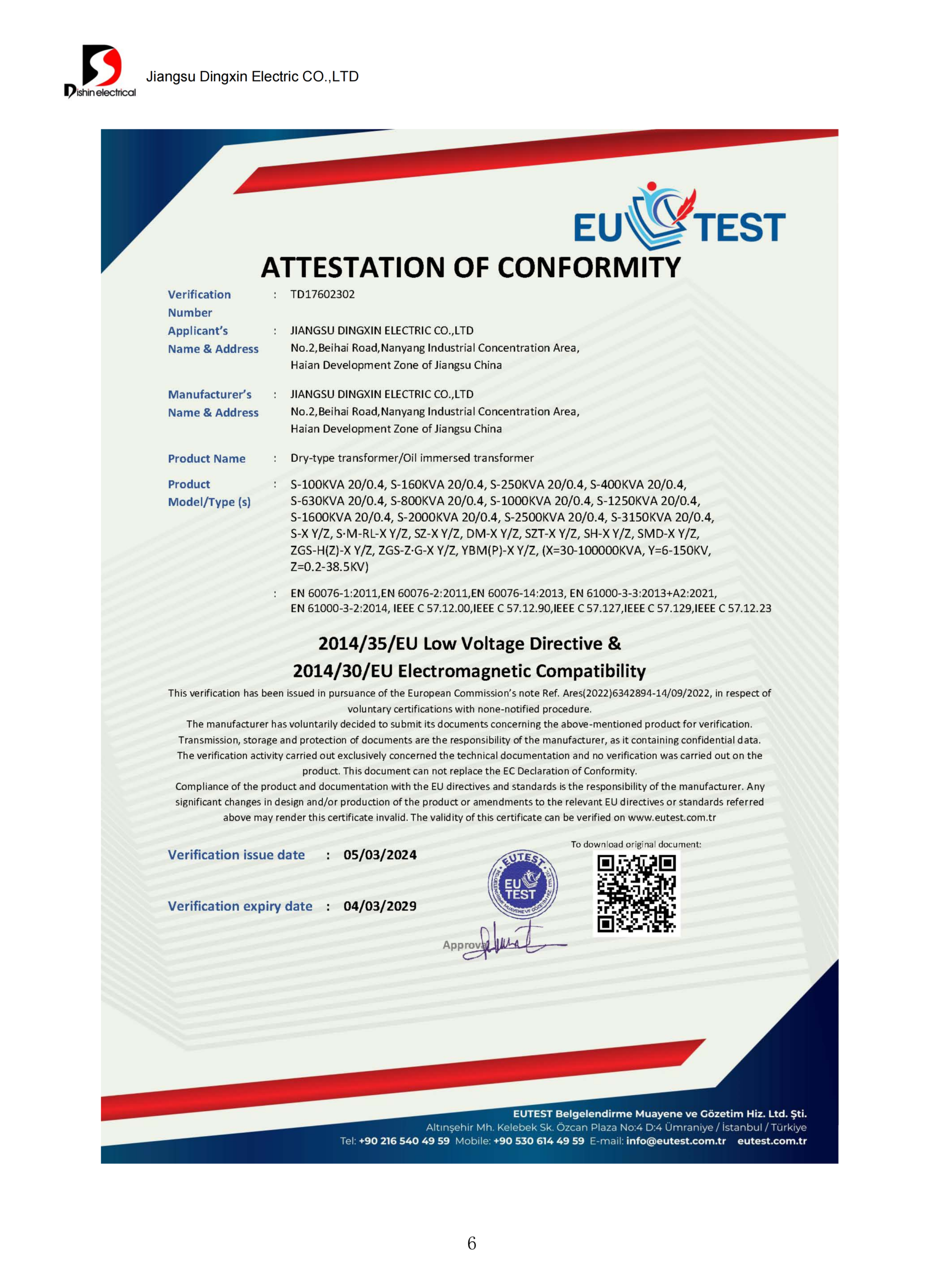
Frequency, efficiency, standard, and certification checked first
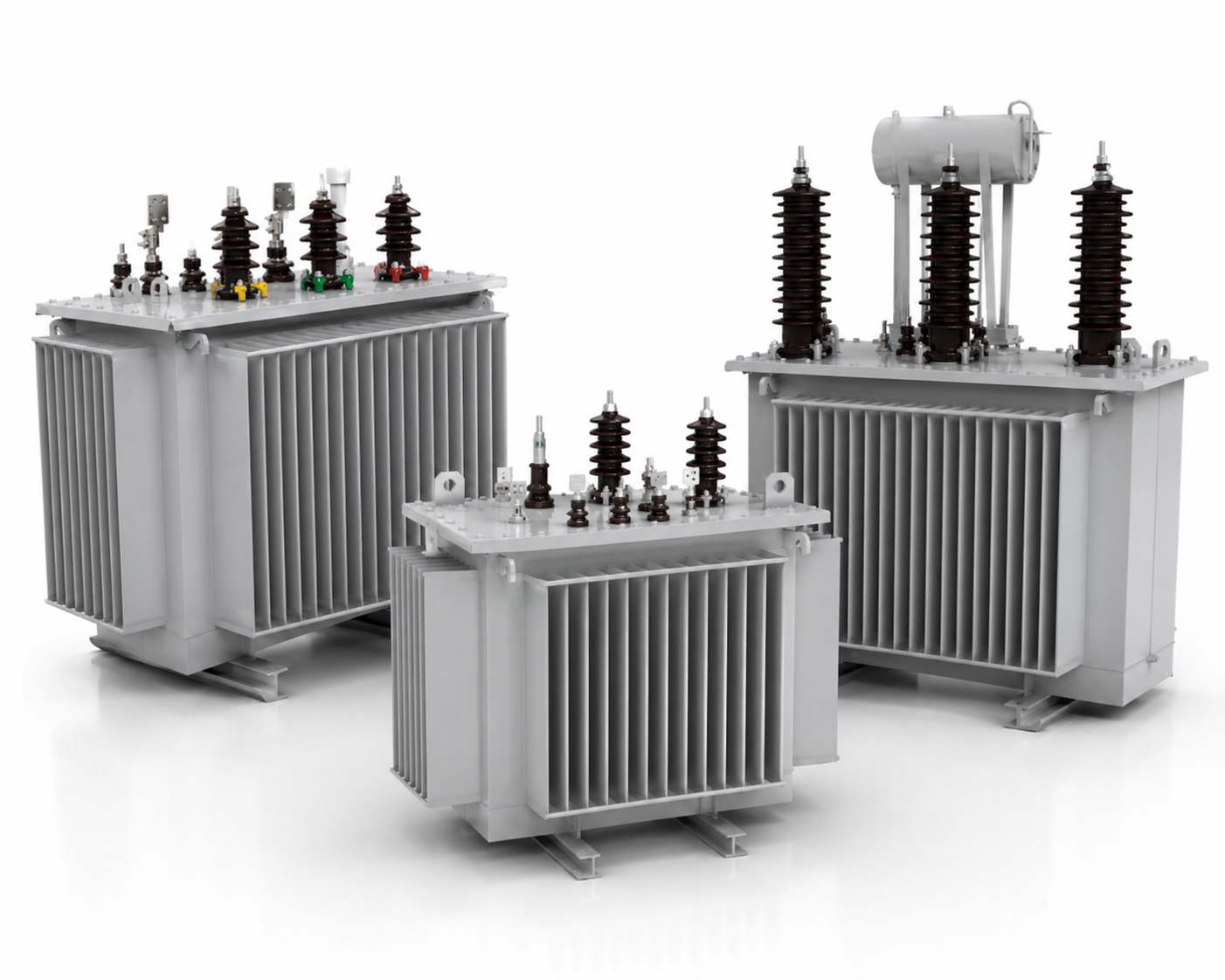
S11-M: 30–3150 kVA
Range shown in the supplied 10 kV family table
S13-M: 30–1600 kVA
Visible rows in the supplied 10 kV table
6 / 6.3 / 10 kV
S11-M primary-voltage options in the local table
0.4 kV
Listed secondary voltage; project values require confirmation
Yyn0 / Dyn11
Listed connection-group options
Indoor or outdoor
Local reference conditions include both placements
Keep Air and Moisture Outside the Oil-Insulation System
Because the windings are immersed inside the transformer, the electrical properties of the oil-insulation system depend on controlled oil quality. Moisture ingress, oxygen, contaminant pathways, and oil contamination can accelerate dielectric degradation. Although some suppliers describe these units as virtually maintenance-free, claims of minimal maintenance, service life, performance and longevity, and reliable operation still depend on verified conditions.
- Humid air or moisture reaching the insulating oil
- Oxidation, sludge formation, and reduced dielectric margin
- Corrosion or aging at a weld, gasket, valve, or cable interface
- The main transformer tank is filled and closed without a conservator tank
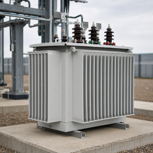
- Corrugated walls flex as mineral oil temperatures change
- Tank construction, fittings, and pressure relief devices work as one system
- Confirm leak testing, tank pressure-test basis, and oil-processing records
- Define visual inspection, oil sample, and alarm-access requirements
- Freeze the operating envelope before approving the transformer design
A sealed tank can still develop air ingress as gaskets age. Describing this sealed type, or hermetically sealed distribution transformers generally, as completely sealed doesn’t remove inspection duties or the risk of oil leakage. Field reporting on transformer air leaks and a transformer-oil preservation patent record support the moisture-and-oxygen mechanism, not Talite product performance.
Why the corrugated tank matters
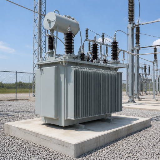
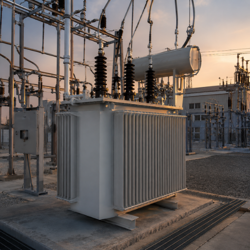
Insulating oil expands and contracts as temperature and load change. Corrugated-wall expansion and contraction create controlled space for oil to expand while the oil remains inside the approved system boundary. Talite’s local product document describes corrugated walls that flex with this volume change, while a conservator system uses a separate oil reservoir and breather path.
System Focus Areas
Oil expansion
Sealed tank transformer
Dielectric insulating fluid
Moisture and contaminants
Inspection access
Specify a Talite S11-M or S13-M Oil-Immersed Distribution Transformer
A model-name mismatch creates both technical and commercial risk because “hermetic transformer” or “corrugated tank transformer” isn't a complete specification. Talite engineers match the required kVA, voltage, frequency, taps, vector group, winding, losses, impedance, cooling, insulation, accessories, and destination rules. Review the broader oil-immersed distribution transformer range when the tank architecture is still open.
Talite’s supplied table lists 30–3150 kVA, primary options of 6/6.3/10 kV, a 0.4 kV secondary, Yyn0 or Dyn11, and two tap arrangements. It gives no-load loss, load loss, short-circuit impedance, current, dimensions, body weight, oil weight, total weight, and track gauge by rating.
- Short-circuit impedance: 4.0% through 500 kVA; 4.5% from 630 kVA in the supplied table
- Listed installation reference: indoor or outdoor, altitude up to 1000 m
- Listed ambient reference: −25°C minimum and +40°C maximum
The visible local rows cover 30–1600 kVA with primary options of 6/6.3/10/10.5/11 kV, 0.4 kV secondary, Yyn0 or Dyn11, and a ±5% tap range. The document also lists no-load current, no-load and load losses, impedance, sound level, dimensions, total weight, and track gauge.
- The S13-M designation is treated here as a Talite catalog family, not a current regulatory efficiency grade
- Current loss and efficiency limits must be checked against the project standard and test basis
- 60 Hz, BIL, destination labeling, and certification aren't inferred from the local 50 Hz-style family sheet
- The visible corrugated walls, terminals, bushings, and lifting points are configuration features; ratings cannot be identified from appearance alone.
| Rated capacity | HV / LV | Connection | No-load / load loss | Impedance | Oil / total weight | Dimensions (L×W×H) |
|---|---|---|---|---|---|---|
| 30 kVA | 6/6.3/10 kV / 0.4 kV | Yyn0 / Dyn11 | 100 W / 600 W | 4.0% | 70 / 300 kg | 800×660×940 mm |
| 100 kVA | 6/6.3/10 kV / 0.4 kV | Yyn0 / Dyn11 | 200 W / 1500 W | 4.0% | 115 / 600 kg | 940×740×1080 mm |
| 315 kVA | 6/6.3/10 kV / 0.4 kV | Yyn0 / Dyn11 | 480 W / 3650 W | 4.0% | 220 / 1300 kg | 1500×860×1270 mm |
| 630 kVA | 6/6.3/10 kV / 0.4 kV | Yyn0 / Dyn11 | 810 W / 6200 W | 4.5% | 320 / 2050 kg | 1660×950×1460 mm |
| 1000 kVA | 6/6.3/10 kV / 0.4 kV | Yyn0 / Dyn11 | 1150 W / 10300 W | 4.5% | 570 / 3030 kg | 1800×1090×1620 mm |
| 1600 kVA | 6/6.3/10 kV / 0.4 kV | Yyn0 / Dyn11 | 1640 W / 14500 W | 4.5% | 750 / 4350 kg | 1980×1180×1800 mm |
| 2500 kVA | 6/6.3/10 kV / 0.4 kV | Yyn0 / Dyn11 | 2310 W / 20240 W | 4.5% | 1080 / 5820 kg | 2250×1490×2150 mm |
| 3150 kVA | 6/6.3/10 kV / 0.4 kV | Yyn0 / Dyn11 | 2730 W / 23760 W | 4.5% | 1180 / 7350 kg | 2460×1650×2320 mm |
| Rated capacity | HV / LV | Connection | No-load / load loss | Impedance | Sound level | Dimensions / total weight |
|---|---|---|---|---|---|---|
| 30 kVA | 6/6.3/10/10.5/11 kV / 0.4 kV | Yyn0 / Dyn11 | 0.08 / 0.60 kW | 4.0% | 50 dB | 730×420×900 mm / 280 kg |
| 100 kVA | 6/6.3/10/10.5/11 kV / 0.4 kV | Yyn0 / Dyn11 | 0.15 / 1.50 kW | 4.0% | 52 dB | 870×520×1110 mm / 600 kg |
| 315 kVA | 6/6.3/10/10.5/11 kV / 0.4 kV | Yyn0 / Dyn11 | 0.34 / 3.65 kW | 4.0% | 58 dB | 1175×760×1280 mm / 1190 kg |
| 630 kVA | 6/6.3/10/10.5/11 kV / 0.4 kV | Yyn0 / Dyn11 | 0.57 / 6.20 kW | 4.5% | 60 dB | 1450×910×1400 mm / 2027 kg |
| 1000 kVA | 6/6.3/10/10.5/11 kV / 0.4 kV | Yyn0 / Dyn11 | 0.83 / 10.30 kW | 4.5% | 62 dB | 1740×1220×1500 mm / 2600 kg |
| 1600 kVA | 6/6.3/10/10.5/11 kV / 0.4 kV | Yyn0 / Dyn11 | 1.17 / 14.50 kW | 4.5% | 59 dB | 1890×1320×1620 mm / 3380 kg |
Source: Talite-supplied S11-M/S13-M product document. These rows are catalog references, not guaranteed order values; compare the selected edition with the current SAMR standard record, then confirm frequency, tolerances, materials, temperature-rise basis, losses, dimensions, and accessories in the approved data sheet.
Send the required power ratings, voltage schedule, frequency, load profile, and destination so Talite can identify gaps before quotation.
Get a model-fit and exception review →Hermetically Sealed vs Conservator-Type Transformers: Choose by Project Boundary
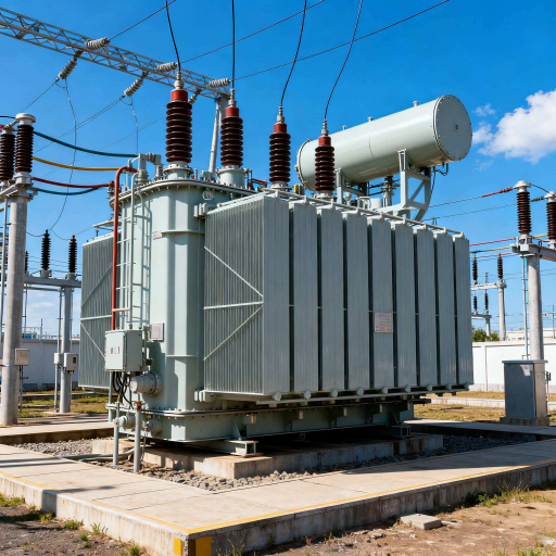
For an industrial buyer comparing 30–3150 kVA reference ratings, the sealed-versus-conservator decision starts with oil-volume control. Conservator transformers and sealed units handle air exposure, service access, pressure behavior, cooling, footprint, and maintenance requirements differently, so Talite treats the choice as a project trade-off rather than a universal ranking. Lower routine attention doesn't eliminate oil changes authorized by the manufacturer or other lifecycle risks.
- A compact configuration without a conservator tank
- Reduced breather and silica maintenance points
- Controlled separation of oil from ambient air under the specified envelope
- Harsh or remote environments where routine access is constrained
- A supplier can prove tank integrity, accessory scope, and service procedure
- Frequent oil sampling or modification with specific access requirements
- Higher-capacity cooling arrangements outside the offered sealed family
- An owner standard written around a conservator or oil-preservation system
- A pressure or temperature envelope not covered by the proposed design
- Future load growth that changes the selected rating or thermal assumptions
| Decision dimension | Hermetically sealed oil-immersed design | Conservator type transformer | Question for the supplier |
|---|---|---|---|
| Oil-volume change | Corrugated tank walls or another engineered sealed-volume method expand and contract | A separate conservator tank provides an oil reservoir | What temperature and pressure envelope was used for tank design? |
| Air-contact path | No routine conservator breather path; fittings and seals still require integrity control | Breathing is managed through the conservator and silica gel breathers or another preservation system | Which joints, valves, and gaskets are included in leak testing? |
| Routine service points | Fewer breather-related tasks, but inspection, protection checks, and model-specific oil work remain | Breather, conservator, oil level, and preservation-system tasks are part of the plan | Provide the exact inspection and service schedule for this model. |
| Oil sampling | Possible only through the provided fittings and approved procedure; access varies by design | Sampling access is commonly included, but the method still follows the model and owner policy | Where is the sample point, and how is air entry controlled? |
| Pressure management | Tank flexibility, internal volume, temperature range, and pressure relief must be coordinated | The conservator decouples part of the oil-volume change from the main tank | Request the operating basis, test pressure, relief-device data, and alarm logic. |
| Cooling expansion | Confirm that the sealed design and cooling surface fit the rating and load cycle | Larger or more complex power transformers may use additional cooling arrangements | What load profile, ambient temperature, and future overload case were reviewed? |
Oil sampling method and frequency vary by model and owner policy. The correct approach depends on the supplied fittings, manufacturer instructions, qualified personnel, insurer or statutory requirements, and the asset owner’s condition-monitoring program. The oil-preservation mechanism described in this patent record is background evidence, not a universal service procedure.
Talite compares both designs using one shared rating, loss basis, site envelope, test scope, and set of service-access assumptions before comparing price.
Verify Hermetic Integrity, Tests, and Applicable Standards
The assumption that a “sealed transformer” label proves construction quality or destination compliance isn't supportable on its own. A buyer can't infer regulatory category from the word sealed, because engineering descriptions and legal product definitions may use the same words differently.
Hermetic Integrity Triangle: Expansion, Pressure, and Ingress
Before technical sign-off, review expansion, pressure, and ingress together. A gap on any side can compromise the insulation system, blur responsibility, or leave an apparently compliant offer unsupported.
Expansion
Confirm how the oil volume responds across minimum ambient, maximum ambient, temperature rise, load cycle, and transport conditions. Request the design basis linking oil expansion, corrugated-wall movement, and available internal volume.
- Specified ambient and temperature-rise basis
- Tank design note or approved drawing
- Load and overload assumptions
Pressure
A 35 kPa setting isn't treated as a universal value, so Talite doesn't use it as a page-level product promise. The order must identify the pressure-test basis, relief device, contacts, alarm or trip logic, and required certificates.
- Normal and abnormal pressure boundary
- Leak and pressure-test records
- Relief-device model and setting basis
Ingress
Ingress control depends on weld quality, gasket and valve selection, oil processing, assembly cleanliness, and final leak testing. Moisture entering the transformer matters because water can reduce dielectric strength while oxygen contributes to oxidation and sludge mechanisms.
- Vacuum drying, filtration, and filling procedure
- Joint, gasket, valve, and terminal inspection
- Final sealing and dispatch condition
“Our engineering review does not stop at the word sealed. We need to see how expansion is absorbed, how pressure is managed, and how every credible ingress path is verified for the offered configuration.”— Talite Engineering Team
Standards and destination prequalification
China standard edition
The official SAMR record identifies GB/T 6451-2023 as the current technical-parameter standard for oil-immersed power transformers, effective from April 1, 2024. The order must identify the applicable edition rather than repeating an older catalog reference.
Energy-efficiency basis
The official SAMR service lists GB 20052-2024 for minimum energy-efficiency limits and grades, effective from February 1, 2025. S11-M or S13-M isn't used here as proof of a current efficiency grade.
Destination classification
For a United States project, 10 CFR 431.192 separately defines 10–5000 kVA liquid-immersed distribution transformers and a dry-type “sealed transformer.” Frequency, voltage, efficiency, test procedure, labeling, and exceptions require a product-specific review.
Control Price, Lead-Time, and Document Scope Before Purchase
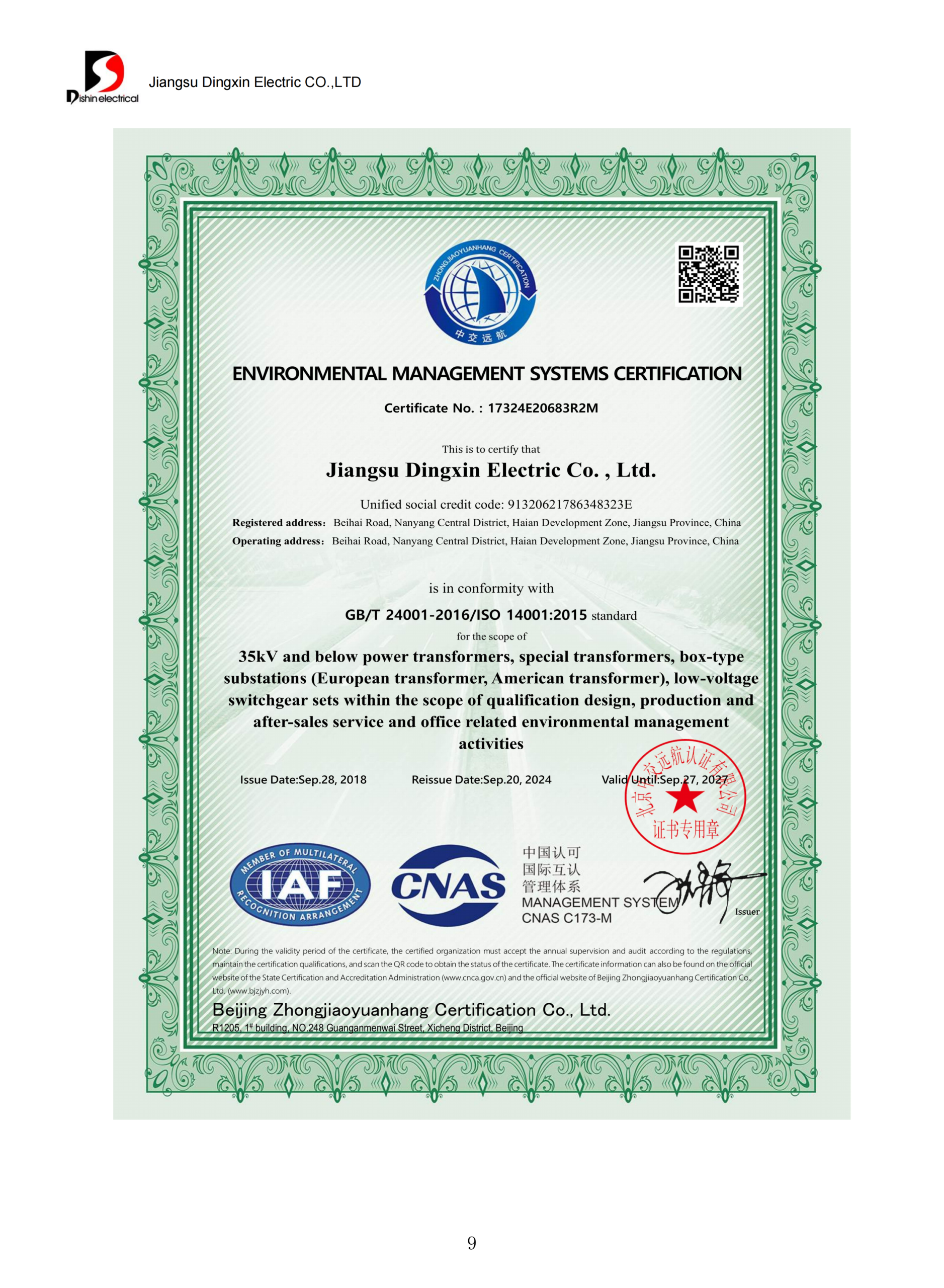
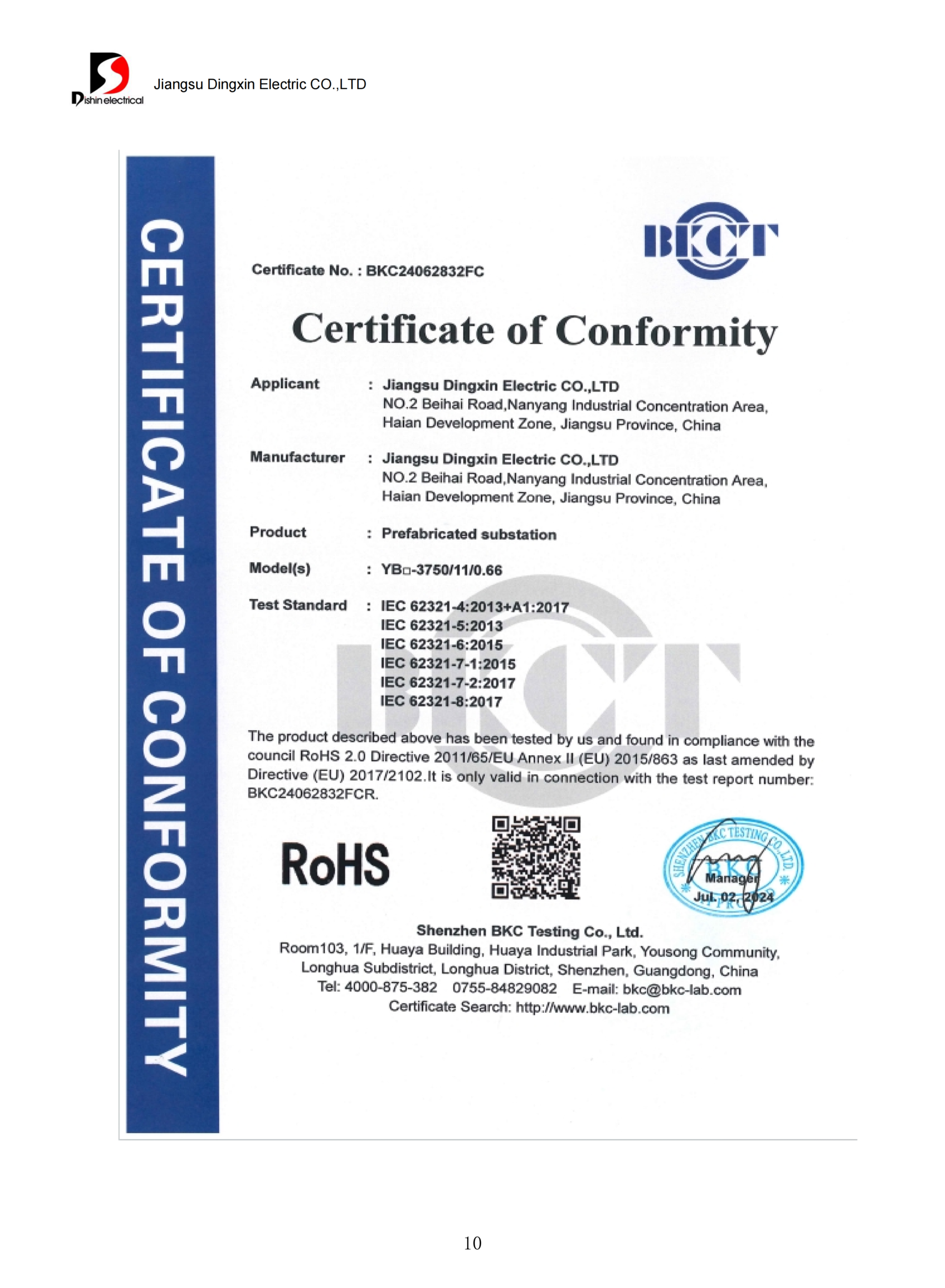
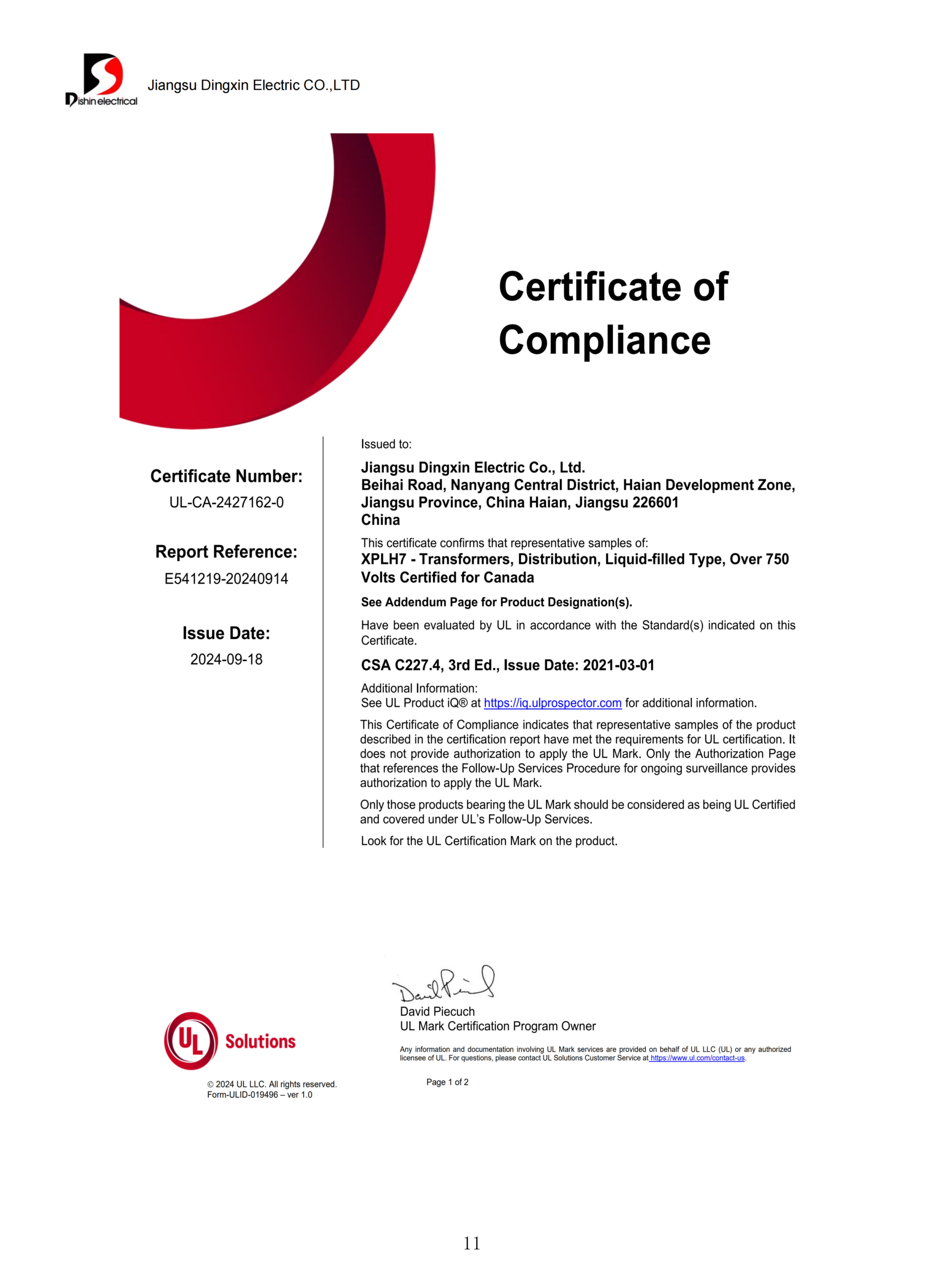
Buyers comparing hermetically sealed transformer manufacturers risk approving an incomplete offer based on a low headline price when excluded tests, accessories, documents, or logistics return as changes. Talite makes price meaningful by fixing the electrical rating, losses, materials, liquid, destination, packing, and supplier responsibilities first. Use the planned distribution transformer manufacturer verification guide to structure the supplier-screening stage.
- kVA and voltage ratio
- Frequency and vector group
- Impedance, losses, taps, and insulation level
- Load profile and temperature-rise basis
- Winding and core specification
- Mineral oil or agreed insulating liquid
- Bushings, terminals, gauges, valves, and monitoring
- Coating, hardware, and spares
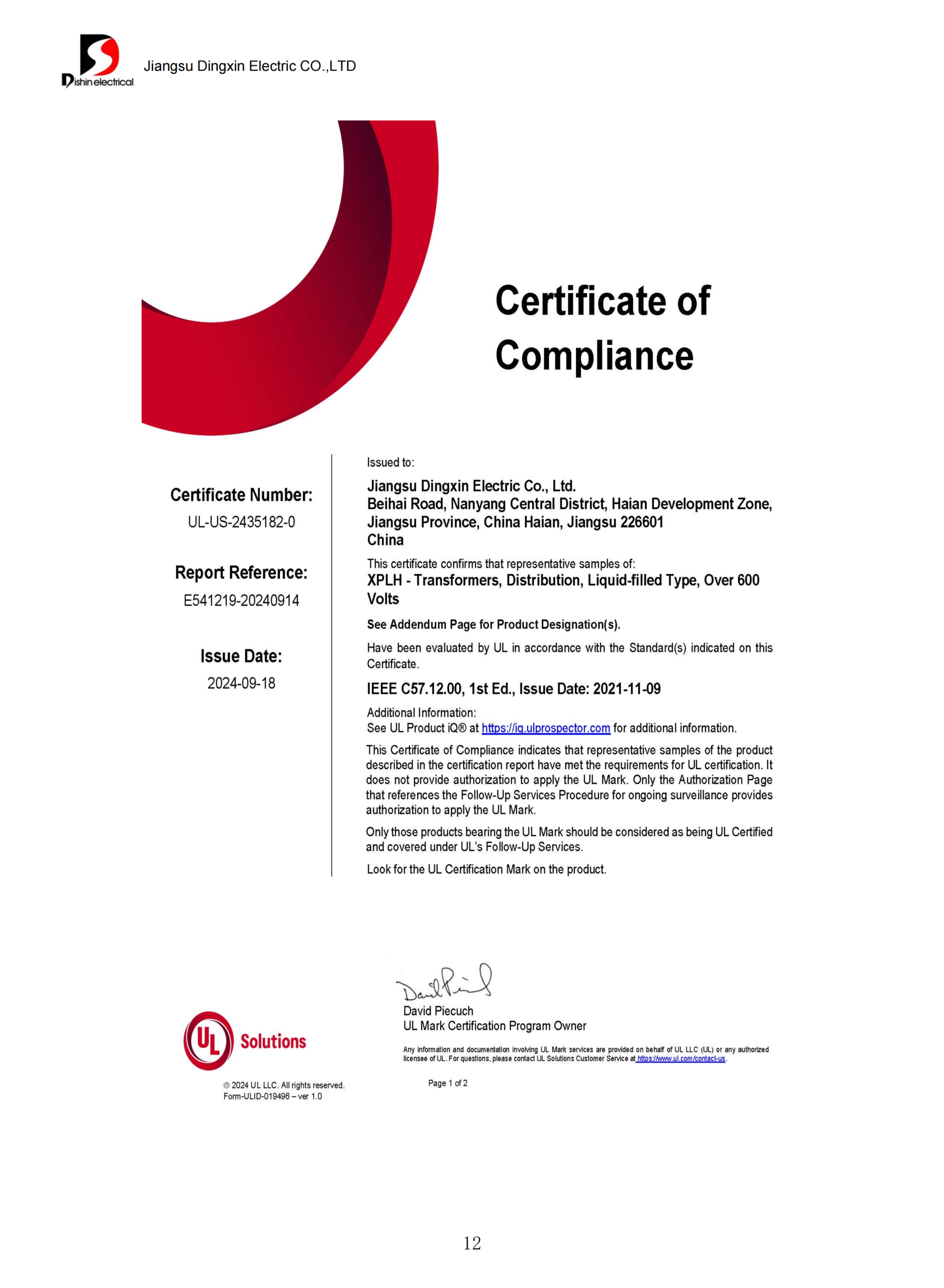
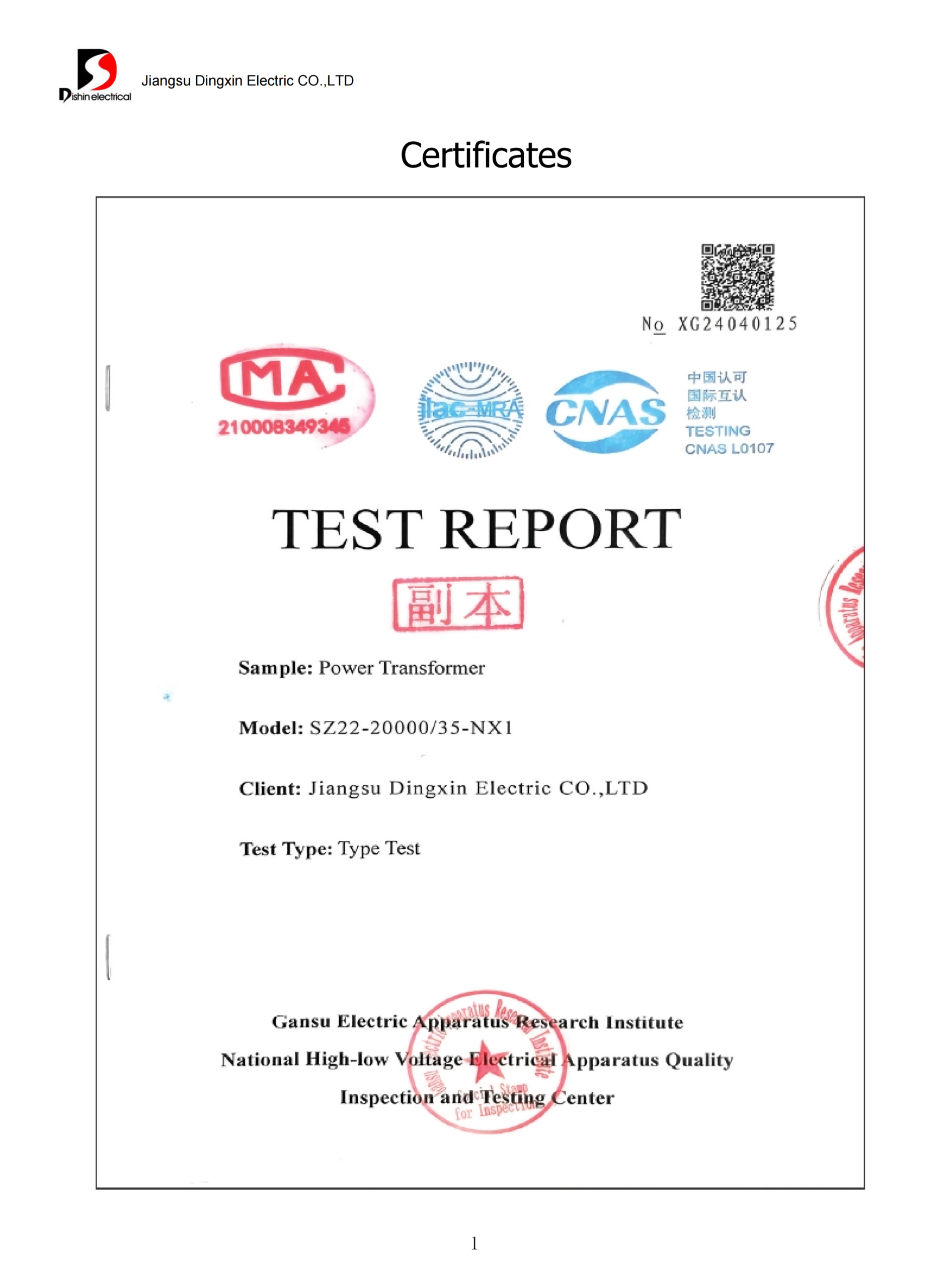
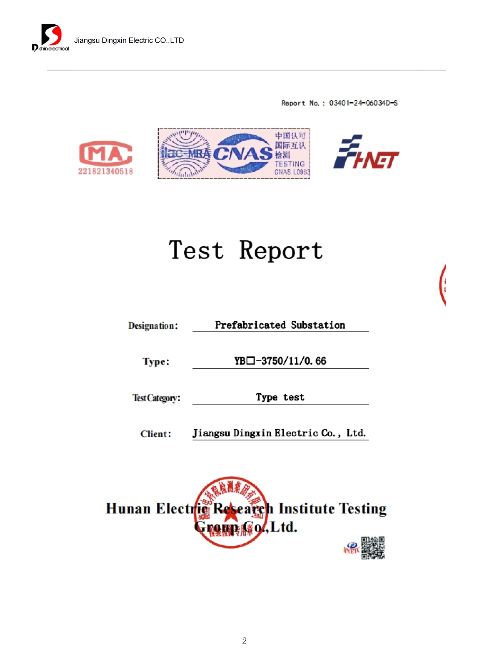
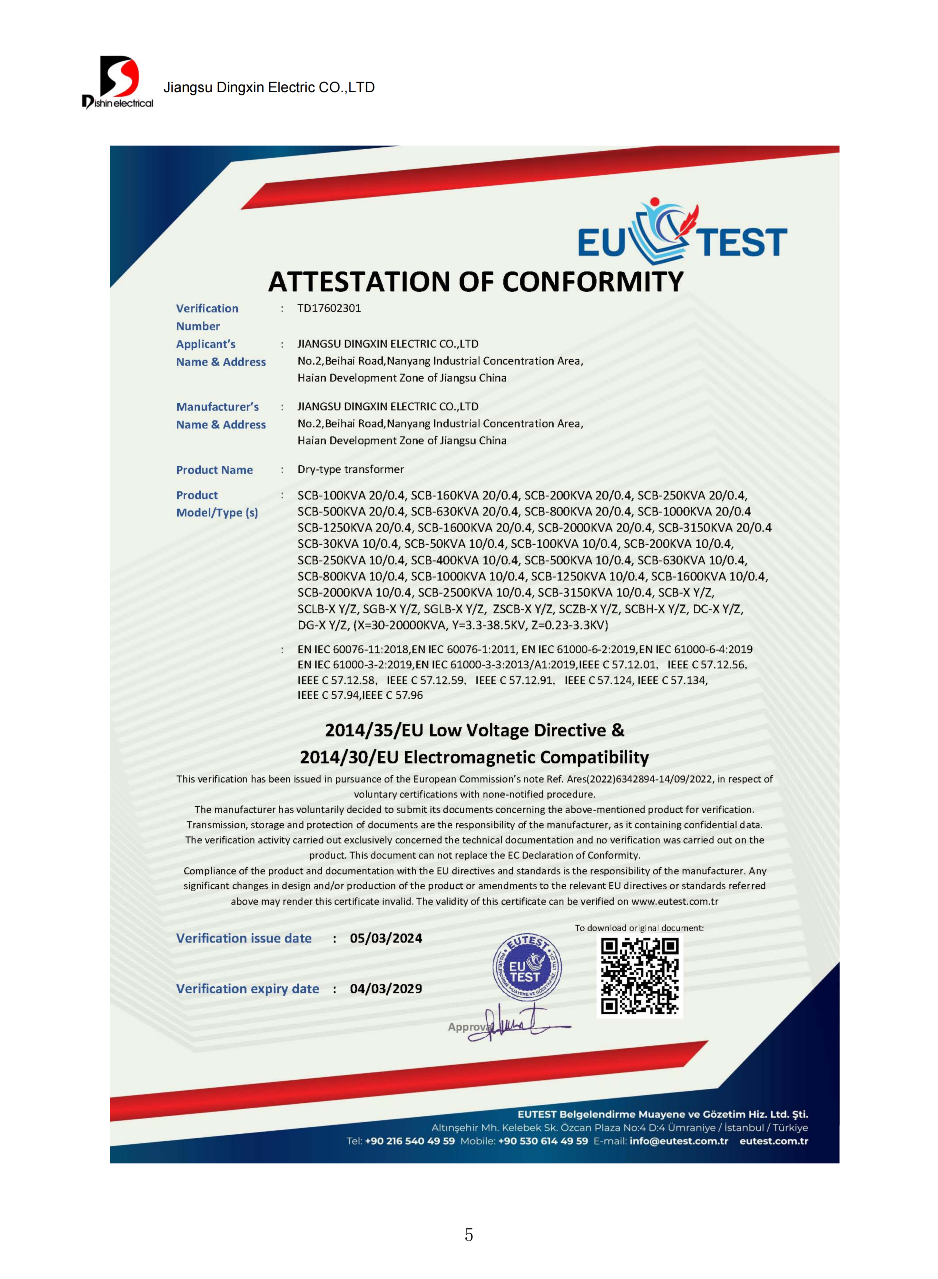
- Routine, type, and special tests
- Third-party witness or hold points
- Loss tolerance and test method
- Document review and approval cycles
- Quantity and design-release sequence
- Destination, packing, and transport interface
- Incoterm and unloading responsibilities
- Site support, warranty, and spare scope by contract
Bronze lifecycle-value screen
No Talite project dataset supports a universal savings, operational life, or payback number for this page. A quotation therefore uses the following boundary to compare sealed and conservator alternatives before you insert tariff, load, maintenance, outage, installation, and financing assumptions. That Federal Register test-procedure record remains separate from any Talite lifecycle claim.
- Normalize purchase price, accessories, tests, shipping, installation, and commissioning.
- Value no-load and load losses against the same duty cycle and evaluation period.
- List inspection, breather or silica tasks, oil service, consumables, and access requirements for each design.
- Add the cost of owner-mandated monitoring, spares, outage preparation, and disposal responsibilities.
- Stress-test the result against load growth, tariff changes, environmental exposure, and service access.
Documents to freeze before order release
Technical approval
- Guaranteed technical particulars
- General arrangement and foundation interface
- Nameplate, schematic, terminal plan, and accessory data
- Deviation and clarification register
Quality and tests
- Inspection and test plan
- Routine-test report format
- Type or special test evidence
- Witness, calibration, and release records
Shipping and handover
- Packing and preservation method
- Transport condition and receiving checks
- Installation, filling, and service instructions
- Final document index and contract warranty terms
Technical Selection & Planning Tools
Frequently Asked Questions About Hermetically Sealed Transformers
Provide kVA, primary and secondary voltage, frequency, phase, vector group, taps, impedance, loss limits, insulation level, load profile, site conditions, destination, applicable standards, accessories, test scope, quantity, and delivery boundary. If data is missing, send the load list, single-line diagram, or existing nameplate so Talite can issue a gap list.
Compare oil expansion, ambient-air exposure, pressure behavior, cooling, service access, and the owner’s maintenance policy. Select against the full project boundary, not a generic “lower maintenance” claim.
Talite’s supplied S11-M 10 kV table lists 30–3150 kVA, while the visible S13-M rows cover 30–1600 kVA. Treat both as reference families and confirm rating, voltage, frequency, losses, dimensions, standard edition, materials, and accessories for the order. For China-market terminology, compare the chosen edition with the SAMR record.
Sampling depends on the model’s fittings and approved method. Confirm the sample point, tools, qualified-personnel rules, and oil-restoration steps before work begins.
Site filling isn't a generic maintenance step. Ask the manufacturer to define vacuum level, oil quality, moisture limits, filling and venting sequence, sealing method, post-work tests, acceptance criteria, required tools, environmental controls, and technician qualifications. Record the approved method for keeping moisture from entering before anyone opens the sealed boundary.
A sealed design isn't always immune to leakage or air ingress. Welds, gaskets, valves, terminals, or fittings can age or be damaged, so specify leak testing and a receiving inspection.
Order documents can separate routine tests, available type or special tests, witness points, calibration evidence, guaranteed particulars, drawings, nameplate, accessory data, inspection records, packing records, manuals, certificates, and deviation schedules. Define the file format, language, review cycle, approval status, and delivery date for each item. The selected standard, destination, configuration, and contract determine the final register.
Limits include the pressure-temperature envelope and more procedure-sensitive service access. Higher ratings or cooling demands may favor another transformer type.
No fixed filtration interval applies to every sealed unit. Build the decision from the manufacturer’s instructions, the oil-preservation arrangement, sample access, owner policy, insurer or statutory rules, operating history, visual inspection, dissolved-gas or oil-test findings when applicable, and evidence of moisture or contamination. Document who may open the system, how air entry is controlled, which acceptance limits apply, and how the sealed condition is restored after intervention.