Get in touch with Toplit Transformer Co., Ltd Company

Combined Substation Transformer
Combined Substation Transformer — 3360 kVA, 23 kV Loop-Type Pad-Mounted Unit
Talite holds a combined substation transformer on record for underground power distribution, rated 3360 kVA at 23 kV and documented for both ring-network and terminal service. Buyers in this market use the phrase for the compartmentalized pad-mounted type that carries switching and protection hardware in the same enclosure as the transformer body. Everything below sets out what that record fixes and what your project still has to specify.
Engineer-reviewed quote within 24 hours on business days
Production scheduled at 10 weeks after drawing approval
Single sets accepted
Routine test reports ship with the order
Quote turnaround
Within 24 hours on business days, reviewed by an engineer
Production lead time
10 weeks after drawing approval
Order size
Minimum order quantity: 1 set — single pieces are accepted
Payment terms
T/T: 50% deposit before production and 50% balance before shipment
Trade terms
FOB; other Incoterms quoted on request
With every shipment
Routine test reports and the agreed technical document package
Verified Product Record and Documented Operating Roles
Talite’s product document describes a loop-type pad-mounted compartmentalized transformer rated 3360 kVA at 23 kV. It records two operating roles: connection into a ring-network supply, and terminal distribution service. Those two roles, the rated capacity and the rated voltage are what the record fixes; every remaining parameter is set on your approved drawing.
Bushing-Count Feed Test
Buyers and installers routinely disagree about whether a padmount transformer is loop-capable, and the argument is usually settled by counting bushings rather than by reading a catalogue. A radial feed transformer and a loop-feed unit look alike from ten paces, so bushing layout is the physical signature that decides it.
Catalogue wording does not always survive contact with the unit on the pad, which is why this test uses what an installer can count rather than what a datasheet asserts.
| What you count | Feed arrangement | What it enables | What it does not enable |
|---|---|---|---|
| Three high-voltage bushings | Radial feed | One incoming three-phase circuit terminating at the unit | No second source, no pass-through to a downstream unit |
| Six high-voltage bushings in two sets of three | Loop feed, labelled H1A–H3A and H1B–H3B[3] within the connector and bushing arrangements IEEE Std C57.12.34 covers[1] | Cable entry on the A side and exit on the B side, so units can be strung together | Automatic transfer; the selection is a switching action |
| Six bushings, B side capped or fitted with elbow arresters | Loop-feed unit installed in a radial circuit | Future conversion without changing the tank | Any second-source benefit while the B side stays dead |
| Three bushings with rotatable feed-through inserts | Radial unit extended | Adding arresters or a second cable set | Selecting between an A side and a B side |
| Internal bayonet fuse on the primary of each unit | Either arrangement | Isolating a faulted unit so the rest of the circuit stays energised | Protecting against a fault upstream of the fuse |
| Three two-position loadbreak switches versus one four-position switch | Loop feed | Independent control of the coil, the A side and the B side | The four-position device offers exactly four combinations, not more |
Open-Point Continuity Boundary
A loop-feed transformer is not a substitute for a network that actually carries redundancy, and treating it as one is the most expensive misunderstanding in this product category. A six-bushing layout buys you the physical ability to accept two cable directions, and nothing beyond that.
| Capability | Delivered by the transformer | Delivered by the system around it |
|---|---|---|
| Physical ability to accept two cable directions | Yes — the six-bushing layout | — |
| Ability to select between Feed A and Feed B | Yes — the internal oil-immersed loadbreak switches | — |
| An actual second source of supply | No | Feeder design and substation topology |
| Restoration after a cable fault | No | Switching at the open point, manual or automated |
| Uninterrupted transfer with no momentary loss | Only with the configuration specified for it | Protection scheme and switching sequence |
| Isolation of one faulted unit in a string | Yes — the primary bayonet fuse | Coordination with upstream protection |
A common assumption is that cabling transformers together creates a loop system. It does not. A string fed from one point still goes dark when that point fails, and only a circuit reaching multiple sources on the power grid changes that.[3]
Utilities also operate loop circuits open at a point, so restoration is a switching action rather than an automatic property of the equipment.[4]
Configuration Choices That Change the Build
Capacity and primary voltage alone do not define a buildable unit. Each choice below changes the tank, the bill of materials or the test scope, so each one belongs in the quotation request rather than in a later revision.
Winding conductor
Options
Copper or aluminium
Why engineers pick it
Copper reduces winding volume for an equivalent kVA; aluminium lowers material cost and mass. The choice moves both the load loss and the shipping weight.
What it affects
Load loss, tank size, total mass, price
Confirmed at
Drawing review, before the quotation is issued
Insulating medium
Options
Mineral oil or a less-flammable ester fluid
Why engineers pick it
Fire code, occupied-building proximity and environmental rules often decide this before performance does.
What it affects
Fire classification, permitting, fluid volume, lead time
Confirmed at
Drawing review, with the site fire requirement stated
Connection & grounding
Options
Delta or wye primary; wye secondary with a neutral bushing, grounded or resistance-earthed
Why engineers pick it
The connection has to match the upstream system earthing and the downstream protection philosophy, not the other way round.
What it affects
Fault current, protection settings, neutral arrangement
Confirmed at
Drawing review, against your single-line diagram
Tap arrangement
Options
De-energised tap changer; ±2 × 2.5 % on the high-voltage winding is one arrangement
Why engineers pick it
Taps absorb long-term feeder voltage drift without a rebuild. A wide tap range has a regulatory consequence — see the classification screen below.
What it affects
Voltage regulation, regulatory classification
Confirmed at
Drawing review, with the measured or modelled feeder voltage
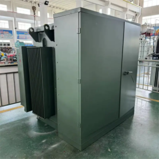
Another configuration
Send the ratings and the connection arrangement with your drawing and we will confirm buildability and price in the quotation. Transformer solutions outside this record are quoted on their own merits rather than assumed from it.
For a different mounting arrangement or rating, start from the Talite pad-mounted transformer range.
Enclosure, Connection & Protection
The specifications below are the ones a compartmentalized pad-mounted unit is normally written around. Each row names the governing document or the physical interface so that your specification writer has something to match against.
| Item | Reference or interface | What it governs | Confirmed by |
|---|---|---|---|
| Bushing and terminal arrangement | IEEE Std C57.12.34[1] | Connector, bushing and terminal arrangements for radial or loop-feed systems | Your feed arrangement on the drawing |
| Separable connector interface | 200 A loadbreak elbow or 600 A deadbreak T-body | Cable termination method and whether the connection is switchable under load | Cable size and the switching method your crew will use |
| Surge protection | Metal-oxide arresters, elbow or parking-stand mounted | Protection of the winding insulation against lightning and switching surges | System insulation coordination study |
| Primary overcurrent protection | Bayonet fuse in series with an internal current-limiting fuse | Isolation of a faulted unit from the rest of the circuit | Coordination with upstream feeder protection |
| Load-side switching | Oil-immersed loadbreak switches, two-position or four-position | Source selection and sectionalising within the loop | Operating philosophy for the circuit |
| Enclosure security | Dead-front compartmentalized construction, tamper-resistant fastenings | Public-space installation and unqualified-person exposure | Site access classification |
| Test methods | IEEE Std C57.12.90[2] | How resistance, ratio, loss, impedance and dielectric measurements are carried out | Test scope agreed in the purchase order |
When This Unit Is Not the Right Call
A compartmentalized pad-mounted transformer is a good answer to a narrow question. Where it is the wrong answer, the alternative is usually obvious once the constraint is named.
Several types of transformers serve the same voltage step, so each row below names the situation, what it costs you, and where to look instead.
Situation: You are specifying a combined instrument transformer
Why it works against you
That is a measurement device pairing a current transformer and a voltage transformer in one housing; it feeds meters and relays rather than stepping voltage down to supply load
What to do instead
Search on instrument transformer or combined instrument transformer, and specify accuracy class, rated burden and insulation level instead of kVA
Situation: You need medium-voltage switchgear with metering, feeders and relay protection
Why it works against you
A compartmentalized transformer carries load-break switching and fusing, not a full switchboard
What to do instead
Specify a package or prefabricated substation, where the switchgear, transformer and low-voltage board are engineered as one assembly
Situation: You need automatic restoration after a feeder fault
Why it works against you
Source selection here is a switching action, not an automatic transfer
What to do instead
Add an automatic transfer scheme or automated switchgear at the open point, and specify the transformer to suit it
Situation: The installation is inside an occupied building or an underground vault
Why it works against you
A liquid-immersed pad-mounted unit is built for outdoor, at-grade installation
What to do instead
Consider a cast-resin dry-type transformer, or a less-flammable fluid with the fire rating the code requires
Situation: Secondary voltage above 600 V and a United States efficiency requirement in the specification
Why it works against you
The regulated definition stops at 600 V output, so the efficiency rule does not reach the unit
What to do instead
Set your own loss guarantee and capitalisation factors in the purchase order instead of citing the regulation
Situation: Your load is single-phase residential or light commercial
Why it works against you
A three-phase compartmentalized unit is oversized for that duty and carries switching content the circuit never uses
What to do instead
Look at the single-phase range built for that duty
Situation: You need one unit next week
Why it works against you
This is configured equipment; production is scheduled after drawing approval
What to do instead
Ask about expedited delivery at enquiry, or source a stocked standard rating for the interim
Quotation Drivers and Lead Times
Price follows capacity, voltage class, conductor material, insulating medium, switching and protection content, enclosure treatment and destination requirements. There is no fixed price list for a configured unit, so your figure comes back in a written quotation against the drawing you send.
Total Evaluated Cost,
Not Purchase Price
The cheapest quotation is not always the best evaluated outcome. Loss capitalisation adds the priced value of no-load and load losses to the purchase price, and published procurement guidance for distribution transformers puts lifetime loss cost as high as four times first cost.[7]
Send your no-load and load loss capitalisation factors with the enquiry and the design follows your economics instead of a bare loss limit.
What Moves Your Price
How Your Quotation Is Produced
Quotes are returned within 24 hours on business days, reviewed by an engineer. We do not run an automatic price engine, and that is deliberate: a configured medium-voltage unit has too many interacting choices for a form to price honestly. The engineer who reviews your drawing also returns the buildability notes at no charge.
Market Context
For context on why the schedule question dominates this category: United States distribution transformer lead times averaged 30 weeks in the second quarter of 2025, against a peak above 100 weeks in 2023, while power transformers ran near 128 weeks and generator step-up units near 144 weeks.[6]
Lead Times by Order Stage
Enquiry to written quotation
Within 24 hours on business days
Engineering review of the drawing, buildability notes, price and terms.
Quotation to drawing approval
Set by your review cycle
General arrangement and nameplate drawings issued for your approval.
Drawing approval to shipment
10 weeks after drawing approval
Core and coil manufacture, tanking, assembly and routine testing.
Lead time starts at drawing approval and excludes ocean transit and destination clearance. Expedited delivery is available. Feasibility is confirmed at drawing review rather than promised in advance.
Project Workflow from Enquiry to Shipment
Step 01
Send your inputs
Single-line diagram, ratings, connection arrangement, site conditions and destination.
Step 02
Engineering review
An engineer checks buildability and returns open questions in writing.
Step 03
Written quotation
Price, terms and the test and document scope, returned within 24 hours on business days.
Step 04
Drawing approval
General arrangement and nameplate drawings issued for your written approval, which starts the clock.
Step 05
Manufacture and routine testing
Production scheduled at 10 weeks after drawing approval, with routine tests on the completed unit.
Step 06
Packing, documents and shipment
FOB as standard, with routine test reports and the agreed technical document package.
Who Supplies What
| Input | Owned by | Consequence if it arrives late |
|---|---|---|
| Phase count, frequency and secondary voltage | Project electrical engineer | The unit cannot be designed, so nothing starts |
| Impedance target and protection philosophy | Project electrical engineer | Winding design is provisional and may be reworked |
| Feed arrangement and switching scheme[4] | Utility or network owner | Bushing count and switch selection change the tank |
| Site fire, seismic and environmental rules | Site owner or EPC contractor | Insulating medium and coating change, adding procurement time |
| Utility acceptance requirements | Utility or network owner | A finished unit the utility will not energise |
| Controlled access, working space and vehicle exposure at the pad | Site owner or EPC contractor | Barrier, bollard and enclosure details are added after the design is fixed |
| Test witness and document scope | Buyer | Testing repeats, or shipment waits on paperwork |
| Design, manufacture and routine testing | Talite | — |
Critical Specifications
Two failure modes come up often enough to name. Sizing on kilowatts alone understates demand, because a 1000 kW load at 0.8 power factor is 1250 kVA, which puts a 1000 kVA unit at 125 % of rating in normal service and costs you service life rather than money on day one.
Specifying without checking the utility’s accepted equipment requirements produces a unit that arrives and cannot be energised. If that list requires UL listing or another third-party mark, state it at enquiry so the scope is priced and evidenced instead of assumed.
Product Views and Served Applications
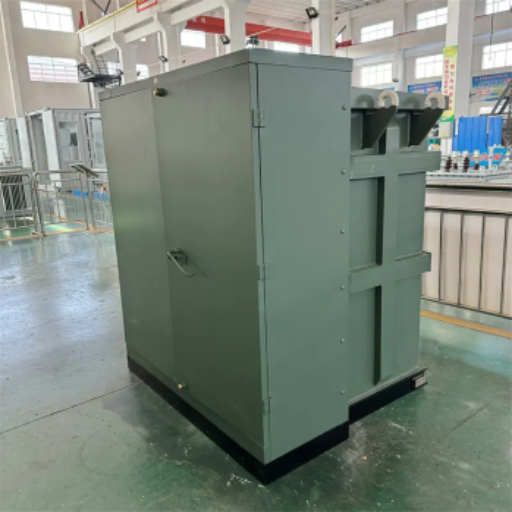
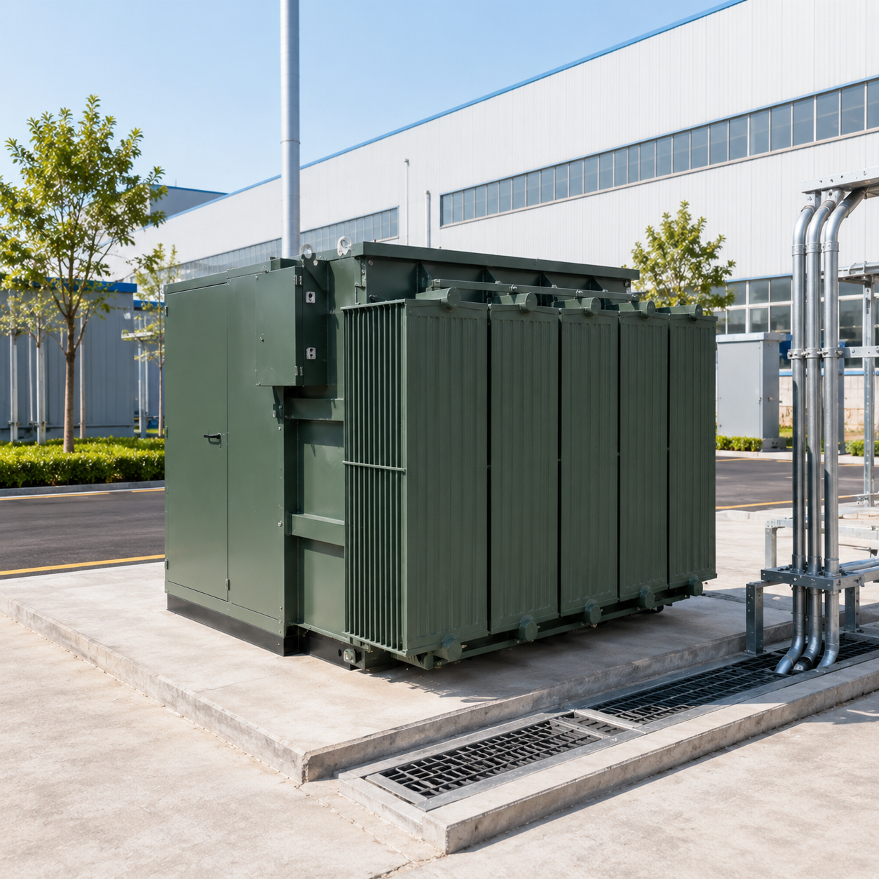
Three views of this equipment family are shown below. They record the enclosure and cooling arrangement of compartmentalized padmount transformers as built, before despatch — the compartmental-type construction IEEE Std C57.12.34 covers.[1]
View 01
Complete unit prepared for despatch, cooling side visible.
View 02
Enclosure three-quarter view on the factory floor.
View 03
Opposite enclosure and cooling side view.
Sectors We Build For
Utility distribution
Cable-fed loops and terminal points on medium-voltage networks downstream of the transmission system, where the feed arrangement is set by the network owner.
Industrial plant
Step-down supply points inside manufacturing sites, where impedance and protection coordination govern the specification.
Campus and healthcare
Estates that operate a switched loop for service continuity and need units that accept two cable directions.
Renewable and storage
Collection and interconnection points where the destination grid code drives the classification screen.
Comparing this unit against a package substation or a separate transformer-plus-switchgear build?
See where a different product route fits better →Combined Substation Transformer Configuration Tools
CST Configuration System
Rating Envelope Screen
Seven questions that resolve whether a configured pad-mounted unit sits inside the United States regulated distribution transformer definition, and where it lands against the current equipment standard. Answer what you know; leave the rest for drawing review. Mark the sheet, print it or save it as a PDF, and attach it to your requisition.
Access Screen ToolFeed Configuration Worksheet
Four questions that fix the high-voltage arrangement before the tank is designed. Getting these wrong after drawing approval means a new tank, not a change order.
Open WorksheetProject Input Collector
The inputs a configured pad-mounted transformer cannot be designed without, grouped by who owns them. Tick what you already hold, copy the outstanding list, and send it to the party that owns each line.
Launch CollectorFAQ
Knowledge Base
Combined Substation Transformer FAQs
Find answers to technical specifications, compliance standards, and procurement guidelines for your engineered solutions.
It is a market term rather than a standards category. Buyers use it for a pad-mounted unit that houses the switching and protection hardware in the same enclosure as the transformer body, which equipment standards describe as compartmental-type construction. Because the phrase is not defined in a standard, write the formal description into your specification and keep the market term for search and correspondence.
No, and the two are easy to confuse because search results mix them. Combined instrument transformers pair a current transformer and a voltage transformer in one housing and exist to feed meters, relays and power-quality monitoring with a scaled replica of the line current and voltage. The unit on this page is a power transformer that steps 23 kV down to supply load, and it is specified by capacity, voltage, impedance and feed arrangement rather than by accuracy class and rated burden.
No. A package or prefabricated substation is a wider assembly that engineers medium-voltage switchgear, the transformer and a low-voltage board together. A compartmentalized pad-mounted transformer carries load-break switching and fusing for its own protection but is not a switchboard. If your scope includes feeders, metering and relay protection, you are specifying the package product.
Not necessarily, and usually not. A six-bushing layout and internal loadbreak switches make the unit able to take cable from two directions and to select between them. The second source, the open point and the switching scheme are all parts of the network design, and a string of transformers fed from one source is still a radial arrangement.[3]
Count the high-voltage bushings. Three means radial feed. Six in two sets of three, labelled H1A to H3A and H1B to H3B,[3] means loop feed under IEEE Std C57.12.34.[1] A loop-feed unit installed on a radial circuit will have the B side capped or fitted with elbow arresters.
On the two parameters the record establishes, yes. The active 2022 edition covers units rated 10 MVA and smaller with a high-voltage limit of 34.5 kV and a low-voltage limit of 15 kV.[1] Note that the 2004 edition stopped at 2500 kVA, so an older specification template would place the same unit outside scope. Conformity is a separate question that needs phase, frequency, insulation, cooling, secondary voltage and test evidence.
That depends on the output side, not the primary. The regulated definition requires an output line voltage of 600 V or less, 60 Hz operation, and 10 kVA to 5000 kVA for liquid-immersed units.[5] Thirteen transformer types are excluded by name, including special-impedance units and those with a tap range of 20 % or more. Send the secondary voltage and the impedance target and the screen resolves in one pass.
Your protection study decides it, but there is a regulatory edge worth knowing. For three-phase liquid-immersed units between 750 kVA and 5000 kVA, 5.0 % to 7.5 % is the normal band, and a unit outside it meets the special-impedance definition and leaves the regulated category entirely.[5] Ask for the value your study needs, and expect the classification consequence to be flagged back to you.
Ask for the routine test report format before you order, not after. Ask which measurements come from the unit you are buying rather than from a design-proven sibling. Ask who answers a technical question during manufacture and how fast, because slow answers during a build cost more than the price difference that opened the conversation.
Production runs are scheduled at 10 weeks after drawing approval, confirmed with your quotation, and drawing approval is the point where the clock starts. Expedited delivery is available and feasibility is confirmed at drawing review. Lead times across the United States market for distribution transformers averaged 30 weeks in the second quarter of 2025 against a peak above 100 weeks in 2023, so early enquiry still pays.[6]
A single-line diagram, the ratings including secondary voltage and frequency, the connection and grounding arrangement, the feed arrangement, the site conditions and the destination country. Quotes are returned within 24 hours on business days, reviewed by an engineer. Anything missing comes back as a written question rather than an assumption.
Yes. Minimum order quantity: 1 set — single pieces are accepted, on the same payment and trade terms as a multi-unit order.
Routine test reports and the agreed technical document package ship with your order. The scope of that package, including any design-proven evidence on temperature rise or short-circuit withstand, is agreed in writing before production starts.