Get in touch with Toplit Transformer Co., Ltd Company

Renewable Energy Transformers Built Around Your Grid Interface
Talite builds renewable energy transformers from the electrical duty out: inverter or turbine output, collector voltage, grounding, harmonic profile, site exposure, loss guarantees and evidence for your approval team.
Solar power transformer
Photovoltaic transformer
Wind power transformer
Wind turbine transformer
Talite at a Glance
These evidence-backed markers are starting points, not project guarantees: Talite confirms the applicable duty from the buyer’s RFQ because voltage, loading and environmental risk change the final design.
A useful transformer proposal is not a nameplate plus a price. It is an auditable link between the renewable plant duty, the offered design, the guaranteed values and the documents required for acceptance.
REQUEST PROPOSAL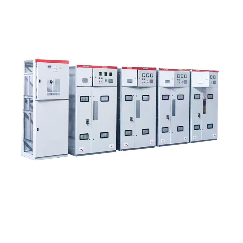
45–12,000 kVA
Our published pad-mounted range supports early family and rating assessment before project-specific design review.4
2.4–46 kV
Our published pad-mounted primary-voltage envelope gives EPC teams an initial routing boundary.
30–3,150 kVA
Our published oil-immersed distribution range provides a second verified equipment route.5
30+ years
We’ve worked in power equipment for over three decades, with engineering and manufacturing coordinated from Jiangsu.
System Active
Solar and Wind Transformer Capabilities
One renewable energy page shouldn’t flatten solar and wind into the same duty. A photovoltaic transformer receives AC from the inverter after the direct current conversion stage and sees daytime cycling.1 A wind turbine transformer sits inside a variable wind power generation and collector system.2
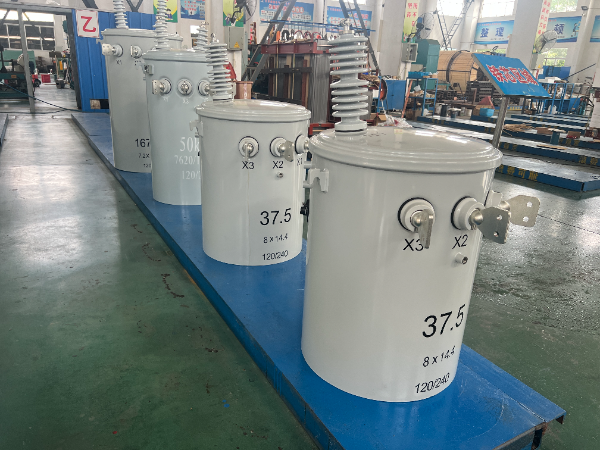
Solar power transformer route
For utility-scale solar systems, we review inverter output, block size, voltage ratio, grounding, harmonic spectrum and expected fluctuation before selecting a liquid-filled or dry-type route. The single-line diagram should also show where the transformer sends solar power into the grid.
- Inverter step-up duty
- PV system collector interface
- Solar panel block loading
- Solar inverter harmonic inputs
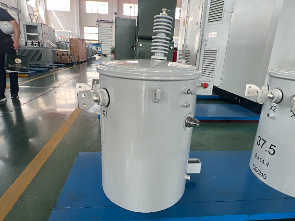
Wind power transformer route
For onshore or offshore wind energy, we distinguish the nacelle or tower-base unit from the collector substation power transformer, then review generator behavior and the power transmission interface.
- Turbine generator step-up
- Wind farm collector duty
- Wind-speed-driven load cycling
- Offshore wind exposure
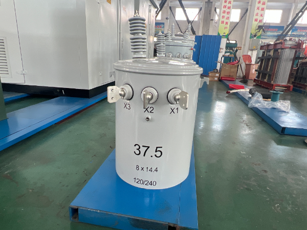
Grid and power distribution route
Where a distribution transformer or substation transformer is the better fit, we align the power system boundary with protection, BIL, impedance, cable entry and the power grid interconnection schedule. See the substation and grid distribution transformer route for the wider utility interface.
- Collector bus definition
- Grounding and vector group
- Fault-current inputs
- Utility document list
The Role of Power Transformers in Renewable Energy Integration
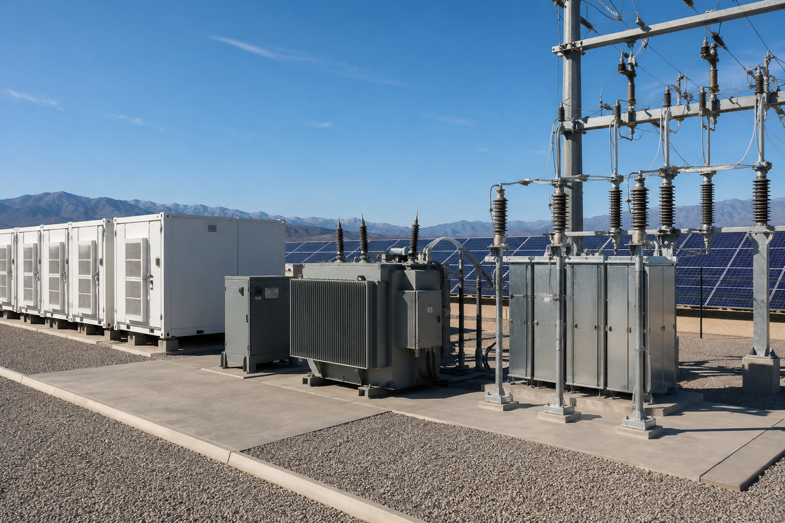
The role of transformers is to move electrical energy between generation equipment, the collector system and the point of interconnection. In a renewable energy plant, the design also has to preserve protection, metering, grounding and power-quality assumptions across each interface.
Source mix
Name the variable renewable energy sources and show whether solar power generation, wind or battery energy storage share the collector.
Voltage path
Show where equipment is stepping up the voltage, every operating voltage level, and the power or energy transmission boundary.
Grid effect
Document how the integration of renewable energy sources affects traditional power grids at the point of interconnection.
Loading
Provide expected fluctuations in power output, reactive range and energy generated across the operating schedule.
Power flow
Define renewable power, energy production metering, and the conditions for feeding renewable energy into the grid.
Equipment family
State whether dry-type transformers, specialized transformers or large power transformers are under consideration, and explain why.
Delivery evidence
Tie transformer technology to the required design and manufacturing records, tests and acceptance criteria.
Controls
Define smart grid solutions through named communication, metering and control interfaces.
| Plant position | What it connects | First engineering question |
|---|---|---|
| Inverter block | Solar inverter output to MV collector | What current spectrum, loading cycle and grounding does the inverter impose? |
| Wind turbine position | Turbine generator or converter to collector | Is the unit in the nacelle, tower or external pad, and what thermal environment follows? |
| Collector substation | Multiple feeders to the grid connection | What voltage regulation, impedance, protection and transmission boundary must the main unit support? |
Lifecycle decisions are measurable
The global energy transition changes the generation mix, but it doesn’t change how a transformer bid should be compared. For an owner planning long-life energy infrastructure, the useful comparison is guaranteed loss, expected loading and shared financial assumptions. This ties energy efficiency to the project’s operating case and supports efficient energy distribution decisions without broad sustainability claims.
Published Talite ranges used for early routing
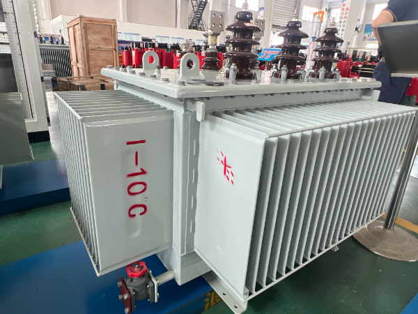
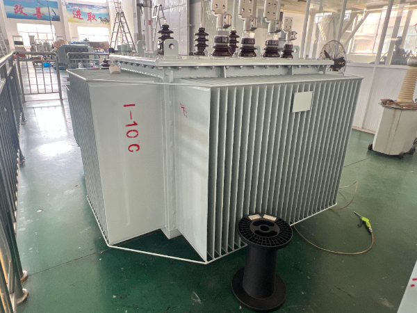
Our pad-mounted reference envelope is 45–12,000 kVA with a 2.4–46 kV primary range and 30–250 kV BIL. Our oil-immersed distribution reference envelope is 30–3,150 kVA; the final offer follows the project specification and design review.
Core, Winding and Insulation Decisions
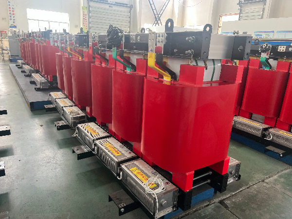
Transformer materials matter because they determine losses, temperature rise, dielectric margin, mass and service behavior. Talite reviews the required guaranteed values before fixing core material, conductor arrangement, winding geometry, insulation system and cooling route.
Magnetic circuit
Core selection starts with the no-load loss target, flux-density strategy, noise limit and project economics. A high efficiency target may justify a different material or section, but the decision belongs in a loss-capitalization comparison rather than a marketing label.
Windings and thermal path
Winding conductor, current density, transposition, ducts and mechanical bracing must work together for the rated current, harmonic content and fault duty. IEEE C57.110 provides the calculation and application context for transformer capability under nonsinusoidal load currents.6 Design review also checks how the transformer operates under cyclic renewable loading.
Insulation coordination
Insulation is set against system voltage, BIL, test level, altitude and the expected overvoltage environment. Selected materials must insulate the active part while preserving cooling and mechanical stability.
Liquid-filled or dry type
A dry-type unit can suit indoor, fire-sensitive or specific maintenance boundaries, while a liquid-filled unit may suit outdoor capacity and thermal requirements. Correct routing follows installation constraints, not a universal preference.
Material questions that belong in technical clarification
Technical ClarificationLoss guarantee
State the no-load and load-loss limits, reference temperature and evaluation method. Talite can then treat core and winding choices as transformer design decisions connected to the commercial comparison.
Mechanical duty
Provide through-fault expectations, transport acceleration, installation route and any seismic requirement. Winding support and active-part restraint should follow the stated mechanical boundary.
Maintenance boundary
Define fluid policy, fire separation, inspection access, monitoring, spares and planned service conditions. This keeps material selection connected to reliability rather than a one-word preference.
Enclosure and Environmental Protection
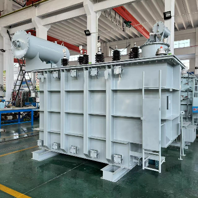
A transformer near salt, dust, humidity, flooding, aggressive industrial atmosphere or offshore wind infrastructure needs a stated protection boundary. For coastal pad-mounted equipment, IEEE C57.12.29 covers enclosure and coating integrity requirements.7
Exposure schedule
- Minimum and maximum ambient
- Altitude and solar radiation
- Salt mist and contamination
- Flood level and drainage
Interface schedule
- Cable boxes or bushings
- Live-front or dead-front arrangement
- Foundation and lifting points
- Monitoring and marshalling
Finish acceptance
- Coating system and color
- Surface-preparation requirement
- Enclosure material
- Inspection evidence
Talite published environmental reference
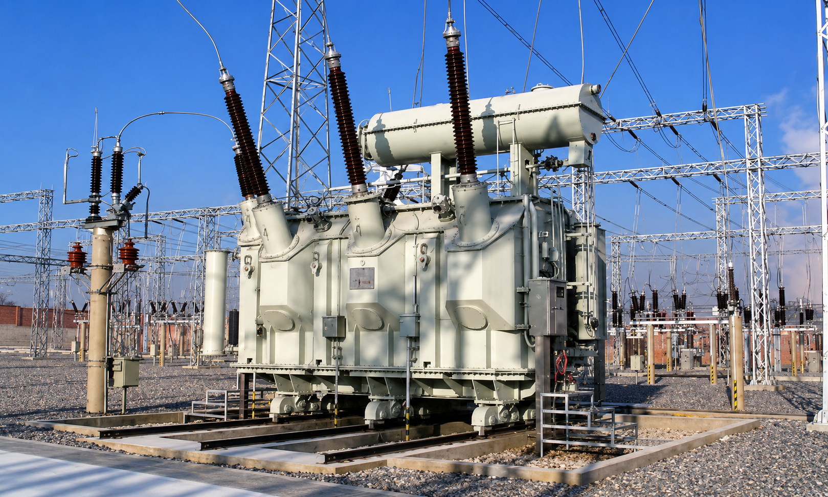
Our oil-immersed distribution reference range covers −25°C to +40°C ambient and installation up to 1,000 m altitude. Conditions outside that envelope are design inputs and require written review.
Electrical Specification and Acceptance Matrix
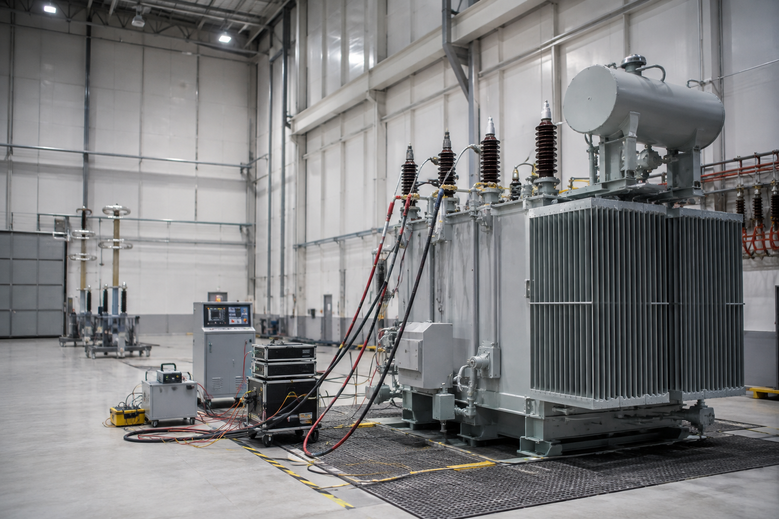
This table is an RFQ input and acceptance map, not a preselected nameplate. Enter project values beside the requested evidence so transformer compatibility can be checked before price becomes the only comparison. For liquid-immersed units, IEEE C57.12.90 provides test methods for the measurements named below.8
| Decision field | Buyer input | Talite output | Acceptance evidence |
|---|---|---|---|
| 1. Rated power | kVA or MVA, loading profile | Rated power and cooling basis | Approved datasheet + routine test record |
| 2. Voltage ratio | LV/MV/HV values in kV | Ratio, taps and insulation levels | Ratio test + nameplate schedule |
| 3. Frequency and phases | 50 Hz or 60 Hz; 1 or 3 phase | Core and winding design basis | Guaranteed technical particulars |
| 4. Vector group and grounding | Required connection and neutral duty | Connection diagram | Vector-group verification |
| 5. Impedance | Target % and tolerance basis | Calculated and guaranteed impedance | Impedance-voltage test |
| 6. Losses | No-load/load limits in W or kW | Guaranteed values at stated temperature | Loss test report |
| 7. Harmonics | Current spectrum, THD, inverter data | Thermal and winding response | Design review note under IEEE C57.110/C57.159 |
| 8. Insulation | System maximum kV and BIL | Insulation coordination | Applied/induced voltage tests |
| 9. Temperature rise | Ambient and rise limit in °C | Cooling and thermal margin | Routine or type-test evidence as specified |
A rating without a loading profile can hide daily solar energy fluctuation, curtailment, overload or reverse-power behavior. For solar energy systems, include the inverter block architecture and the expected relationship between installed DC capacity and transformer AC rating.
A voltage ratio without system grounding can hide insulation and protection consequences. For transformers for wind projects, include the turbine-converter connection, collector neutral treatment, cable lengths and protection philosophy.
Talite’s published range helps identify whether a request belongs in pad-mounted, oil-immersed distribution or another power transformer family. It doesn’t confirm compatibility until the complete duty, interface, test and environmental schedule has been reviewed.
Pricing, Lead Time and Lifecycle Cost
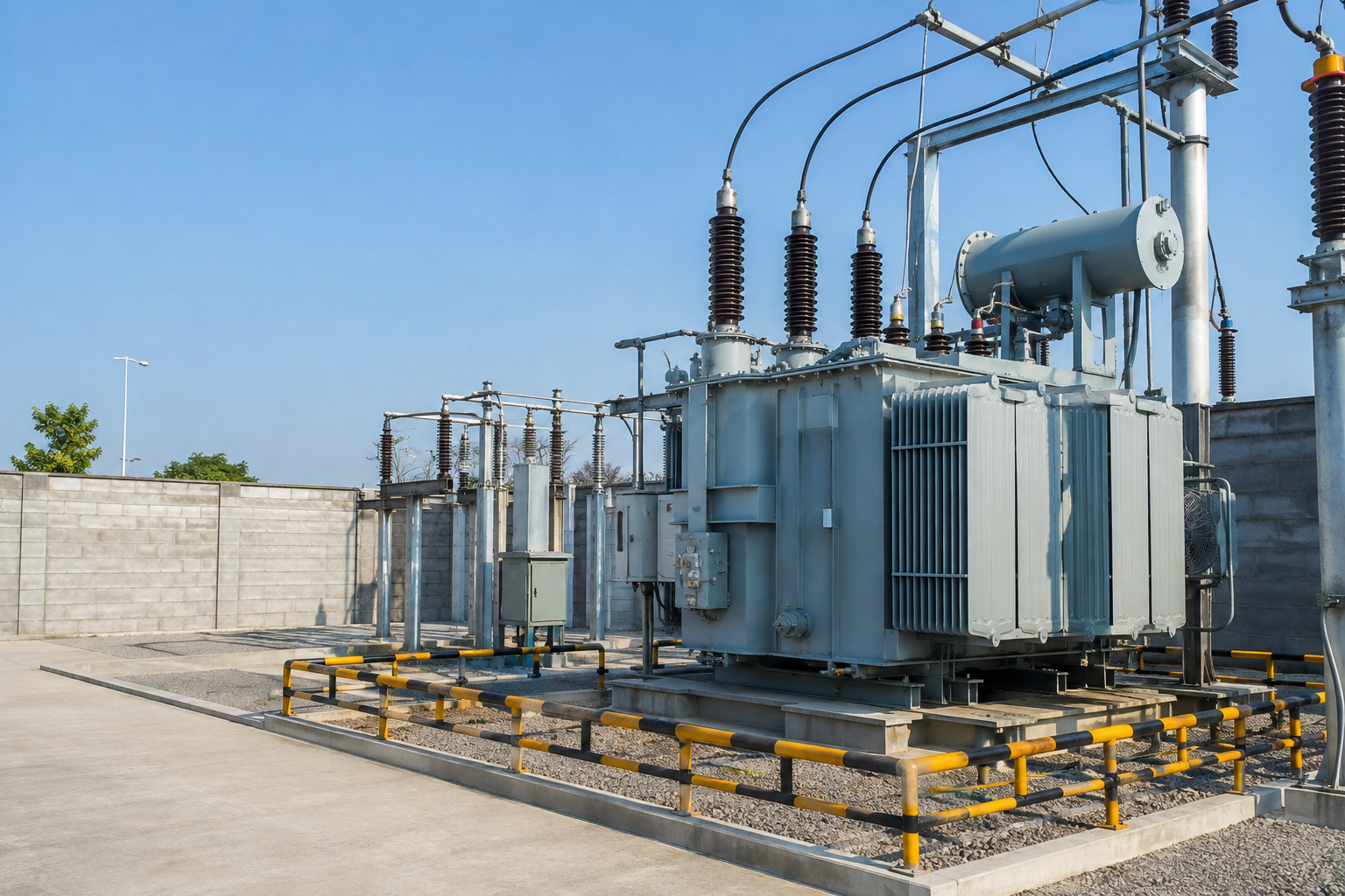
Renewable transformer price moves with electrical duty, guaranteed losses, material selection, accessories, test scope, destination compliance, logistics and production timing. Talite separates those drivers so an EPC team can compare the offered scope rather than normalize hidden exclusions after award.
Price drivers
- kVA/MVA and voltage class
- Guaranteed no-load and load loss
- BIL, impedance and fault duty
- Accessories, tests and inspection
Schedule drivers
- Input completeness
- Drawing approval cycle
- Material and accessory release
- FAT witness and shipping window
Total-cost drivers
- Expected loading
- Energy value per kWh
- Capitalization factors A and B
- Economic life and discount rate
Use losses in the buying equation
For planning, total cost of ownership equals purchase price plus the capitalized value of no-load and load losses. United for Efficiency notes service periods of 30 years or more, so a low initial quote can be a poor lifecycle choice when guaranteed losses are higher.3
A four-column quotation comparison
| Column | Compare | Reason |
|---|---|---|
| Technical basis | Ratings, impedance, losses, temperature rise and standards | Confirms the bids solve the same duty |
| Supply boundary | Accessories, interfaces, spares and exclusions | Prevents missing items from appearing as savings |
| Evidence boundary | Drawings, tests, witness points and manuals | Shows what the buyer can accept and audit |
| Commercial basis | Price, Incoterm, payment, delivery and validity | Creates a comparable award decision |
This loss worksheet uses the accepted A and B factors to place energy losses beside purchase price. It doesn’t manufacture a savings claim; it makes the buyer’s loading, energy-price and financial assumptions explicit.
Layer 1, Approved basis
Specification, single-line diagram, datasheet, compliance schedule and accepted deviations.
Layer 2, Manufacturing release
Approved drawings, bill-of-materials boundary, inspection and test plan, and witness points.
Layer 3, Factory evidence
Winding resistance, ratio, vector group, impedance, no-load loss, load loss and dielectric tests under the agreed standard.
Layer 4, Handover pack
Serial-linked test reports, nameplate data, packing list, handling instructions, manuals and final drawings.
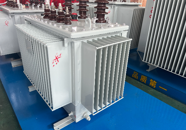
IEC 60076 and the applicable IEEE C57 series provide the standards context; the purchase specification determines the exact routine, type and special tests.
Your RFQ should name witness points, third-party inspection, report format and acceptance criteria before production. Every deviation should be visible and approved rather than buried in a general note.
Acceptance records should answer six questions
What was ordered?
Final datasheet and deviation records define the technical contract.
What was built?
Approved drawings and serial-linked records identify the manufactured unit.
What was tested?
Test plans, instruments, conditions and results define the evidence.
Who witnessed?
Signatures and punch-list closure identify acceptance responsibility.
What ships?
Handover indexes confirm drawings, manuals, reports and packing records.
What remains open?
A visible exception register prevents unresolved items from moving into installation.
How We Work: Talite Engineering and Delivery Workflow
Talite Transformer Co., Ltd. operates from the Hai’an Economic and Technological Development Zone in Nantong, Jiangsu. We integrate R&D, production, and sales so the approved electrical boundary remains visible through manufacturing and commercial coordination.
01
Define the duty
Send the single-line diagram, inverter or turbine data, power rating, voltage ratio, grounding, harmonic information, site conditions and applicable standard.
02
Close technical gaps
Talite returns an input-gap list, equipment route, proposed guaranteed values and a visible deviation schedule for engineering review.
03
Approve drawings and evidence
Confirm the datasheet, general arrangement, interfaces, accessories, inspection plan, document list and acceptance criteria before release.
04
Manufacture and inspect
Production follows the approved basis, with identified hold points and factory acceptance test preparation tied to the order and applicable transformer standard.
05
Complete FAT and handover
Test results, deviations and punch-list items are closed before the shipment milestone is met and the document pack is released.
06
Support installation inputs
Handling, storage, foundation, cable termination and commissioning information are provided within the contracted documentation scope.
- Single-line diagram
- Source equipment data
- Ratings and grounding
- Loss and impedance limits
- Installation location
- Ambient and altitude
- Interfaces and footprint
- Transport constraints
- Applicable standards
- Test and witness scope
- Document schedule
- Destination and Incoterm
If one of these groups is incomplete, Talite can still return a structured gap list. Final transformer design and commercial offer are released only after the missing decision inputs are resolved.
SUBMIT RFQTalite Manufacturing Profile
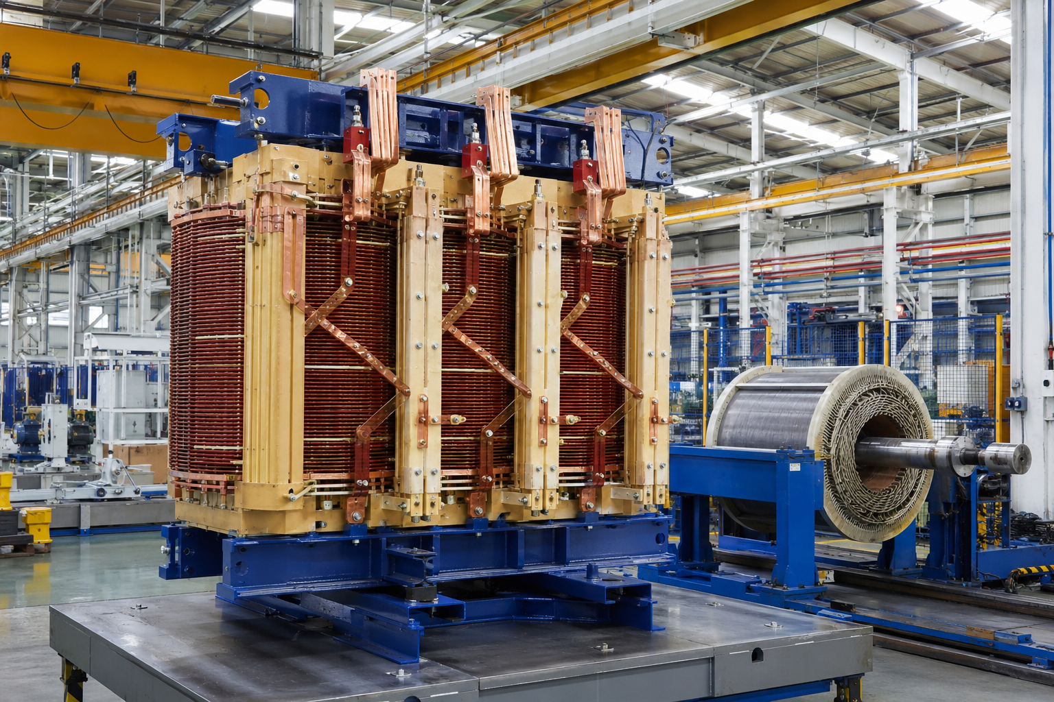
Talite began as Jiangsu Fangteng Industrial Co., Ltd. and has served the power equipment sector for over three decades. As a high-tech enterprise, the company focuses on transformer research, production and international project supply. The transformer manufacturer applies that experience to project-specific duties across the energy sector.
Integrated organization
R&D, production and sales share one company boundary, reducing handoff ambiguity during specification review and order execution.
Published product envelopes
Talite publishes pad-mounted and oil-immersed ranges that support early routing; final capability is confirmed against the full project duty.4, 5 Projects at transmission voltage can continue to the 220 kV power transformer specification page.
Evidence-first proposal
An offer can be evaluated through guaranteed particulars, drawings, deviations, inspection scope and test documents instead of an unsupported performance claim.
What is deliberately absent
This page doesn’t claim an unverified renewable project count, certification scope or factory capacity. Those identity-level proof blocks should be added only when Talite supplies current, auditable records.
What can be verified now
| Evidence | Current status | Buyer use |
|---|---|---|
| Company identity and location | User-confirmed | Supplier onboarding and communication |
| Published product envelopes | Available on Talite product references | Early family and rating route |
| Project-specific guarantees | Created after RFQ review | Technical and commercial comparison |
| Unit-specific test records | Created against the manufactured unit | Factory acceptance and handover |
This separation protects both parties. Talite avoids overclaiming, while the buyer receives evidence at the stage where it can be tied to an offered or manufactured unit.
When a Standard Configuration Is Not Enough
A catalogue-aligned transformer can still be wrong when renewable duty changes the thermal, dielectric, mechanical or environmental boundary. These signals require an explicit engineering review before an offer is treated as compliant.
Electrical red flags
- Missing inverter current spectrum or turbine converter data
- Grounding and vector group left open
- Impedance chosen without fault/protection study
- Loss limits stated without test temperature
- Multiple operating directions or unusual cycling
Site and scope red flags
- Offshore wind or high-salt exposure
- Altitude above the published reference
- Unresolved flood, fire or spill-control boundary
- Unclear cable, bushing or enclosure interface
- FAT witness requested after production
K-factor is not a universal solar answer
A higher K-factor is not a substitute for spectrum data and does not filter harmonics. It provides defined thermal tolerance at additional cost, and that cost trade-off should follow the inverter current spectrum and thermal analysis. IEEE C57.110 supplies the calculation and application framework for this system-level trade-off, so the final compromise should be documented against the measured nonsinusoidal load current.6
Review Protocol

Escalation triggers for a custom review
Grid-study dependency
Escalate when impedance, grounding, inrush, fault duty or voltage regulation depends on an unfinished system study.
Environmental severity
Escalate for salt, humidity, sand, flooding, extreme temperature, high altitude or restricted cooling and maintenance access.
Converter interaction
Escalate when harmonic data, switching behavior or reactive requirements differ from the assumed operating case.
These triggers don’t make the project unsuitable for Talite. They show where a standard selection shortcut would weaken reliability, evidence quality or the final power grid interface.
Request Custom ReviewRenewable Energy Project Engineering Tools
Grid Interface Evidence Checklist
Verify compliance and streamline grid connection requirements for solar and wind power projects.
Access Tool
Transformer Loss TCO Worksheet
Calculate Total Cost of Ownership by evaluating no-load and load losses over the transformer lifespan.
Access Tool
Renewable Transformer Project Risk Compass
Identify, assess, and mitigate potential technical and logistical risks in your renewable energy installations.
Access Tool
Engineering and procurement questions
It’s a power transformer specified for the voltage conversion, isolation, loading and grid interface of renewable generation. This term can include a solar inverter step-up transformer, wind turbine transformer, collector transformer or main substation transformer.
Send power rating, inverter output voltage, grid voltage, frequency, phase, vector group, grounding, harmonic spectrum, loading profile, site conditions, losses, impedance, BIL, accessories, standards and document requirements.
Transformers for photovoltaic inverter duty can face harmonics, cyclic daytime loading, multiple block interfaces and specific grounding or insulation requirements. IEEE C57.159 provides application guidance for distributed photovoltaic inverter transformers.1
It can be installed in the nacelle, tower base or adjacent pad, depending on turbine architecture. A separate collector or main power transformer then connects multiple turbines to the transmission system.
Impedance affects voltage drop, fault current, reactive behavior and protection coordination. It should be selected with the collector-system study rather than copied from a prior project.
No. K-factor selection should follow the inverter current spectrum and thermal analysis because K-rated equipment tolerates harmonic heating but doesn’t remove harmonics.
Compare guaranteed no-load loss and load loss at the stated reference temperature, then apply the same capitalization assumptions to every offer. Purchase price alone doesn’t describe lifecycle cost.
Name the applicable standard and required routine, type and special tests, plus witness points and reporting format. Common routine evidence covers resistance, ratio, vector group, impedance, losses and dielectric performance.
The quotation states the production window after technical scope, material, test and approval requirements are reviewed. Drawing approval, special materials, witness testing and logistics can affect the contract schedule.
Turnaround depends on whether the RFQ includes the electrical duty, site boundary, standards, tests and interfaces needed for engineering review. Missing inputs are returned as a structured gap list before the offer is finalized.
The commercial offer states the payment milestones for the specific order. It also defines currency, Incoterm, inspection scope and document-release conditions.
Normalize duty, guaranteed values, exclusions, deviations, accessories, tests, documents, delivery basis and lifecycle loss cost. Use the Grid Interface Evidence Stack to identify missing evidence before award.
![Pad-Mounted Transformer: How It Works [2026 Guide]](https://toplit-transformer.com/wp-content/uploads/2026/08/pad-mounted-transformer-guide-featured-150x150.png)