Get in touch with Talite Transformer Co., Ltd Company

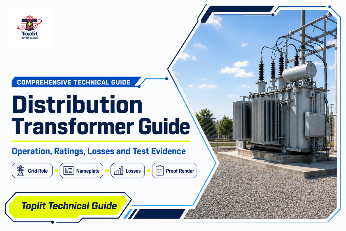
Updated September 2026
A distribution transformer is the voltage-changing link near the load end of an AC power system. It transfers energy through electromagnetic induction, usually stepping a distribution voltage down to a utilization voltage for commercial buildings, equipment, streets, or local networks. That concise definition is useful—but it is not enough to interpret a nameplate, compare loss data, or prove that a unit meets a project requirement.
This guide explains the machine from the inside out: where it sits in the grid, how its windings and magnetic core work, what common type labels mean, how to read ratings, why losses change with load, and what standards or test reports can actually establish. It is educational support content. For product configurations, project selection, quotation evidence, and RFQ discussions, use the Distribution Transformer solution page.
The short version: a label tells you what a transformer is called; a nameplate tells you its declared ratings; a test report tells you what was measured under stated conditions; and the project specification tells you whether that evidence is enough.
What Is a Distribution Transformer, and Where Does It Sit in the Grid?
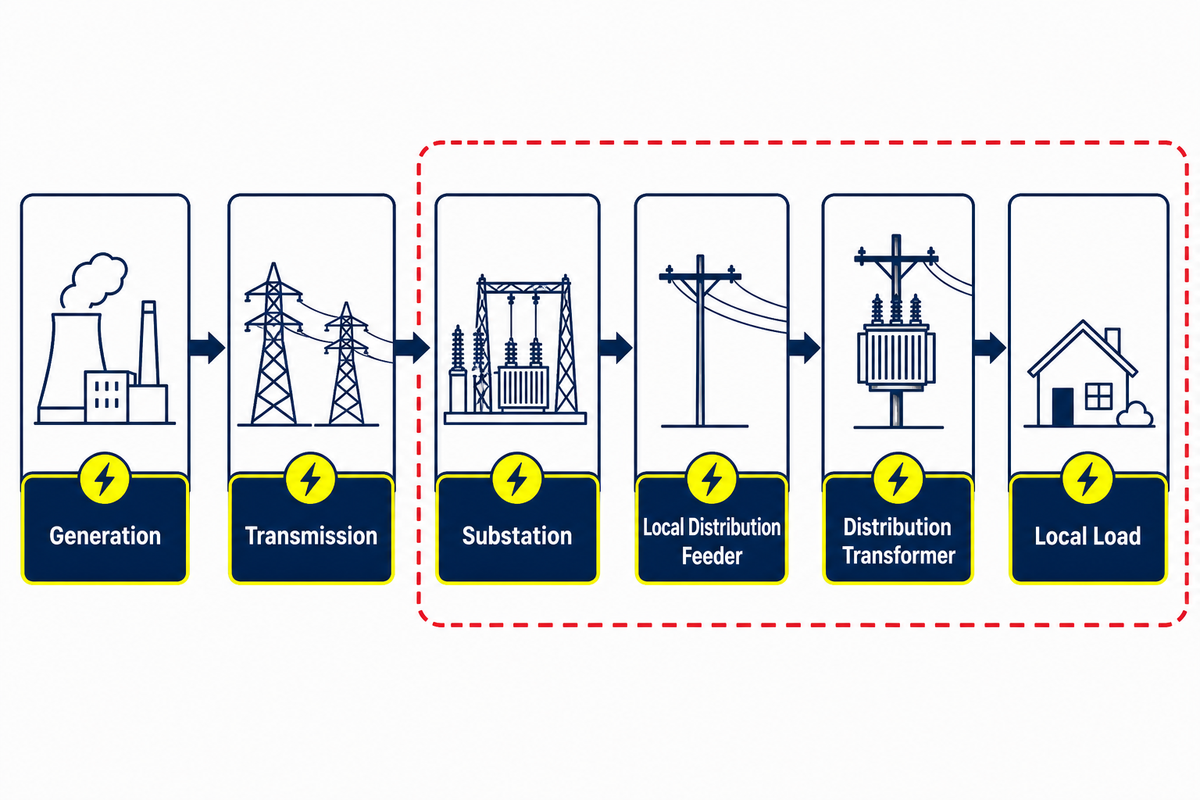
Electric power moves through several voltage layers. Generation and transmission systems carry power over distance. Substations then reduce voltage for local distribution feeders. The distribution transformer performs a later voltage change, closer to the point where electricity will be used. Depending on the network, it may serve one premises, several buildings, an industrial area, or part of a utility feeder.
In conventional power distribution, step-up transformers support efficient transfer before substations and downstream units complete the local voltage change. The final stage may connect high voltage or medium-voltage feeders to a low voltage distribution system and a usable power supply, such as a 230 V service in a relevant market. Distribution transformers are used along overhead power lines, underground distribution circuits, and at commercial and industrial sites. The exact kV-to-voltage relationship belongs to the network design; it is not universal.
The device is static: it has no rotating shaft that produces electricity. Alternating current in one winding establishes changing magnetic flux in the core. That flux links another winding and induces voltage there. The input and output frequency remain the same, while voltage and current change according to the winding relationship and real operating conditions.
Broad industry usage and a legal definition aren’t always identical. In the United States, 10 CFR 431.192 defines covered distribution transformers through several conditions, including input voltage, output voltage, frequency, capacity, and a list of excluded classes. The current text reaches 5,000 kVA for covered liquid-immersed and dry-type categories, with different lower bounds. Those numbers describe that federal rule; they aren’t a worldwide cutoff for every engineer, utility, or standards body.
This distinction matters because an older DOE summary still shows a 2,500 kVA upper figure. When a summary and the current regulation disagree, the live regulation controls the regulatory claim. That is the first use of the Scope-Before-Standard Rule: identify the jurisdiction, equipment class, edition, and effective date before carrying a number into a specification.
Classification check: the practical risk is a definition mismatch. Because a procurement record can outlive a summary page, verify the official 10 CFR scope, the 5,000 kVA condition, and the applicable test report before applying the label. This isn’t a Toplit capability claim or a substitute for IEC 60076 project requirements.
How Does a Distribution Transformer Work?
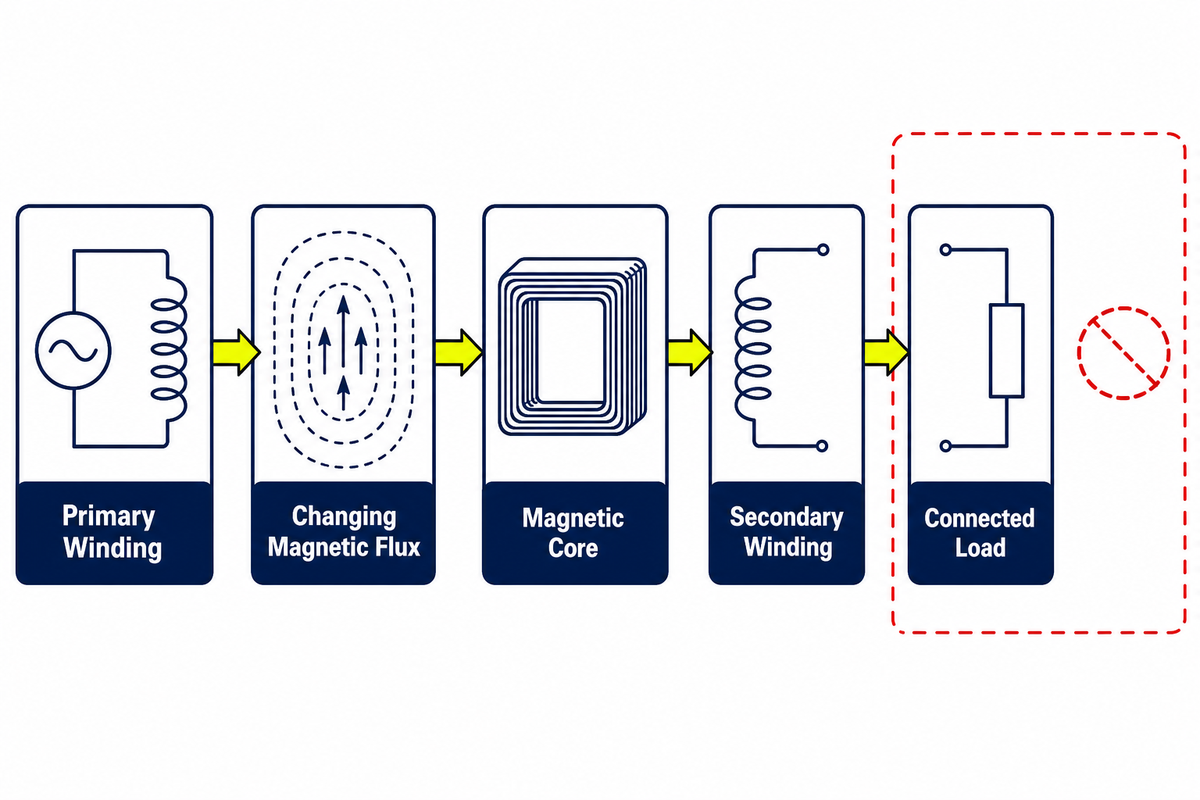
The transformer needs changing magnetic flux. When alternating voltage is applied to the primary winding, a small excitation current establishes flux in the magnetic core. The changing flux links the secondary winding, producing an induced voltage. The Monash University guide to transformers and electricity transmission provides an accessible explanation of this principle.
For an ideal transformer the voltage ratio obeys the turns ratio:
Vprimary / Vsecondary = Nprimary / Nsecondary
If a winding has ten times as many turns as the other, its ideal voltage is ten times greater. Current changes in the opposite direction when power is approximately conserved. Real transformers depart from the ideal model because the windings have resistance, the magnetic circuit needs excitation, flux does not couple perfectly, insulation and cooling have limits, and voltage changes under load.
From voltage ratio to useful power
The primary winding receives AC power at one rated voltage. The core provides a controlled magnetic path. The secondary winding delivers power at another rated voltage. Connections, phase arrangement, impedance, taps, and the load all affect the operating result.
Voltage regulation describes how secondary voltage changes between defined loading conditions. It is influenced by winding resistance, leakage reactance, load current, and power factor. The turns ratio therefore explains the basic voltage relationship but does not predict the complete terminal-voltage behavior of a real unit.
The distribution transformer is designed around declared electrical and thermal conditions, not around the phrase “stepping down the voltage” alone. Real power delivery also involves bushings, terminals, conductors, protection, and the connected load. That wider chain explains why a power-supply transformer label or an ideal voltage equation can’t substitute for the approved system documentation.
Mechanism check: treating a 10:1 turns ratio as a complete performance model is a common mistake because it omits resistance, leakage reactance, excitation, and load behavior. In a procurement application, keep the 50 Hz or 60 Hz rating, IEC 60076 basis, and unit test report together.
Which Distribution Transformer Types Are Common?
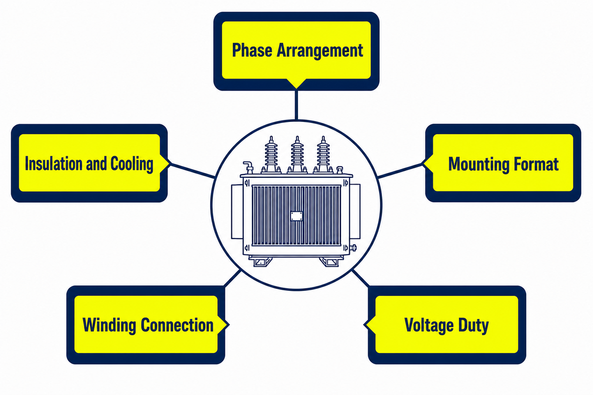
Transformer labels often look like one list, even though they describe different axes. “Three-phase” describes phase arrangement. “Dry-type” describes an insulation and cooling family. “Pad-mounted” describes an installation format. These labels can combine, so they should not be treated as mutually exclusive product ranks.
Single-phase transformers may serve one phase of a distribution arrangement, while three-phase transformers interface with three-phase power systems. Dry-type transformers describe a construction family, not a phase count. Pole units connect near overhead wires; pad-mounted units may sit on prepared concrete pads and connect to underground cables. These are types of transformers by different classification axes, which is why one phase, one enclosure, or one mounting label never describes the whole unit.
| Classification axis | Common labels | What the label tells you | What it does not settle |
|---|---|---|---|
| Phase | Single-phase, three-phase | The phase arrangement of the unit and network interface. | Capacity, mounting, insulation, or suitability for a site. |
| Insulation/cooling family | Liquid-immersed, dry-type | The broad construction used for insulation and heat transfer. | Environmental acceptance, enclosure, losses, or exact cooling class. |
| Installation format | Pole-mounted, pad-mounted, substation-style | How the equipment is physically arranged in a distribution system. | The complete safety, access, civil, cable, or protection design. |
| Winding connection | Delta, wye, or other declared connections | The winding connection and related phase/neutral interface. | Whether the connection is correct for a particular network. |
| Voltage duty | Step-down, step-up, isolation or special duty | The intended transformation function. | Universal product category or regulatory classification. |
Mounting questions deserve their own site and safety analysis. The separate pole-mounted versus pad-mounted transformer comparison owns that decision path. Similarly, this guide does not repeat protection coordination; see the dedicated distribution transformer protection guide when the question moves from equipment meaning to protective-device logic.
Type check: the selection risk is mixing classification axes. Because a dry-type label says nothing about phase or mounting, a procurement application should bind the IEC 60076 scope, approved drawing, installation format, and unit test report instead of guessing from one catalogue term.
How Do You Read a Distribution Transformer Nameplate?
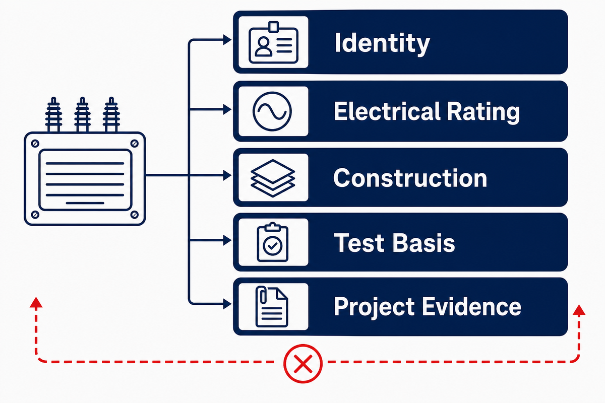
The nameplate is a compact contract of rated conditions. The fastest way to misread it is to treat every field as proof of performance. A better method separates identity, electrical rating, construction, test basis, and project evidence. Each layer answers a different question.
5-Layer Transformer Meaning Stack
- Identity: manufacturer, model, serial number, manufacturing date, and asset reference connect the physical unit to its records.
- Electrical rating: kVA, primary and secondary voltage, phase, frequency, connection, taps, and impedance describe declared electrical conditions.
- Construction: insulation system, cooling class, temperature-rise basis, fluid or dry-type family, enclosure, and total mass describe how the unit is built and rated.
- Test basis: referenced standards and test classifications tell you what framework may apply. They do not prove that every test was performed.
- Project evidence: approved drawings, test reports, certificates where required, study data, and acceptance records connect the rated unit to a real order and site.
| Field category | What it means | Why it matters | What it cannot prove alone |
|---|---|---|---|
| Rated kVA | Declared apparent-power rating under stated conditions. | Connects voltage and rated current. | Correct project size, overload allowance, or annual energy use. |
| Primary/secondary voltage | Nominal winding voltage relationship. | Defines the intended system interfaces. | Actual voltage regulation across the load range. |
| Frequency and phase | Supply frequency and phase arrangement. | Sets fundamental electrical compatibility. | Compatibility with harmonics, grounding, or every load type. |
| Connection/vector group | Winding connection and phase displacement. | Affects neutral availability, parallel operation, and studies. | That the unit can be paralleled without a full compatibility review. |
| Impedance | Declared internal impedance at a stated basis. | Influences voltage drop and fault-current calculations. | Complete short-circuit or protection-coordination result. |
| Tap range | Permitted winding-ratio adjustments. | Supports voltage adjustment within the declared design. | The correct operating tap for a live system. |
| Cooling/temperature rise | Rated thermal arrangement and limit basis. | Connects load, ambient, and heat removal. | Site-specific loading allowance or remaining life. |
| Insulation level/BIL | Declared dielectric withstand coordination basis. | Relates equipment insulation to system stresses. | That the entire installation is correctly coordinated. |
| Standard reference | The named standard or family used as a basis. | Points to scope, test methods, and definitions. | Certification or model-specific compliance without records. |
Rated kVA deserves special care because it isn’t a sizing answer. Load profile, diversity, ambient, voltage, harmonics, future duty, protection, and the governing rules all matter. The existing transformer kVA sizing guide owns that calculation path. For insulation-level interpretation, use the focused transformer BIL guide.
Why Do No-Load and Load Loss Behave Differently?
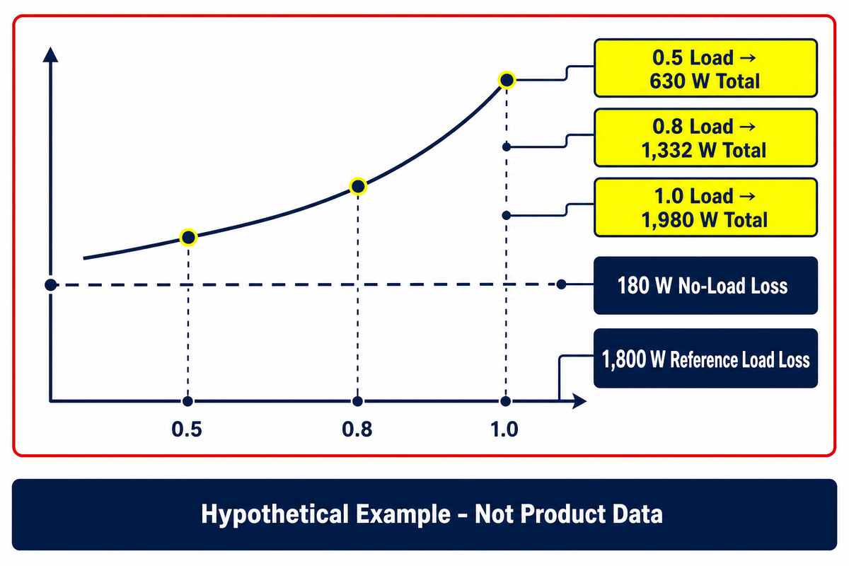
Transformer loss is not one fixed percentage. No-load loss remains while the core is energized at its stated voltage and frequency, even when the external load is small. Load loss is associated with current in the windings and other current-dependent effects. Auxiliary power may also matter when fans, pumps, heaters, monitoring, or control equipment operate.
This teaching approximation separates a near-constant no-load term from a term that grows with the square of per-unit load:
Ptotal ≈ P0 + x2Pk
Here, P0 is the hypothetical no-load loss, Pk is the hypothetical reference load loss, and x is per-unit load. The squared term shows why current-dependent loss grows faster than load fraction. It is a bounded illustration, not a test procedure.
Loss-at-Load Worked Trace
Assume a purely hypothetical transformer has 180 W no-load loss and 1,800 W reference load loss. None of these figures describes a Toplit product.
| Per-unit load x | Calculation | Illustrative total loss | Meaning |
|---|---|---|---|
| 0.50 | 180 W + 0.50² × 1,800 W | 630 W | The current-dependent term contributes 450 W. |
| 0.80 | 180 W + 0.80² × 1,800 W | 1,332 W | The current-dependent term contributes 1,152 W. |
| 1.00 | 180 W + 1.00² × 1,800 W | 1,980 W | The reference load-loss term is fully represented. |
The trace is deliberately simple. It does not represent the different temperature behavior of ohmic and stray loss, harmonic content, waveform distortion, voltage or frequency deviation, auxiliaries, measurement uncertainty, or the correction rules used for certified representations. Because the official Department of Energy procedure measures no-load and load loss separately under defined reference conditions, use the DOE distribution-transformer test-procedure record for that regulatory evidence.
The practical insight is not “half load means half the loss.” No-load loss continues while the unit remains energized, while the current-dependent portion changes sharply with load. Realistic energy comparisons therefore need a load profile and consistent, traceable loss evidence—not only a single efficiency percentage.
At full load, the reference load-loss term in this simple trace is fully represented. Lost electrical energy ultimately appears largely as heat, which the cooling system must manage. Better loss performance may support energy savings and lower energy costs over a stated duty cycle, but “maximum efficiency” is meaningless unless the load point, temperature, waveform, measurement method, and product category are held constant. Claims to reduce energy use need that same evidence boundary.
How Should Efficiency and Voltage Regulation Be Interpreted?
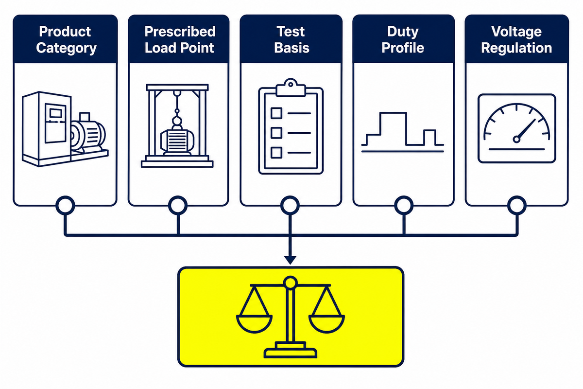
Efficiency is output power divided by input power under stated conditions. Because loss changes with voltage, frequency, temperature, waveform, and load, an efficiency value without its test basis can be misleading. Two units can show similar headline percentages at one prescribed point yet produce different annual energy outcomes under different duty cycles.
The U.S. federal tables make the load-point boundary clear. The current 10 CFR 431.196 states minimum-efficiency tables for covered equipment, with category-specific per-unit load points: 35% for low-voltage dry-type units and 50% for liquid-immersed and medium-voltage dry-type units. Those are conditions of regulatory representation, not statements that every transformer operates at those loads.
Efficiency check: the risk is comparing 35% and 50% results as though they used one definition. Because the Department of Energy applies category-specific conditions, procurement teams should match the official table, unit test report, temperature basis, and application before comparing performance.
What changes in 2029?
The current regulation still uses April 23, 2029 as the manufactured-on-or-after date for amended minimum-efficiency tables. Applicability depends on whether the transformer is covered by the federal definition, its category, rating, and manufacture date. The rule isn’t a worldwide requirement and shouldn’t be inserted into an IEC-market specification without checking the controlling jurisdiction.
In June 2026, DOE issued a Request for Information on supply-chain, manufacturing, material, and other impacts. The RFI gathers information; it is not a completed amendment. As of this September 2026 update, the codified tables and date remain the evidence for what the rule says. Future policy should be checked again when a project is released.
Voltage regulation answers a different question. It describes the change in secondary voltage between defined load conditions. Low loss values do not automatically guarantee the desired voltage regulation, and a nameplate impedance figure cannot replace a system study. Keep energy evidence, terminal-voltage behavior, and network analysis in separate columns.
Every comparison must keep its units and conditions attached. Records stating 50 Hz, 400 V, 800 A, 75 °C, 35%, and 630 W differ materially from records that list only numbers. The same warning applies to 60 Hz, 230 V, 1,000 A, 85 °C, 50%, or 1,980 W: these are unit examples, not Toplit ratings.
What Do IEC 60076, IEEE C57, and Test Reports Actually Prove?
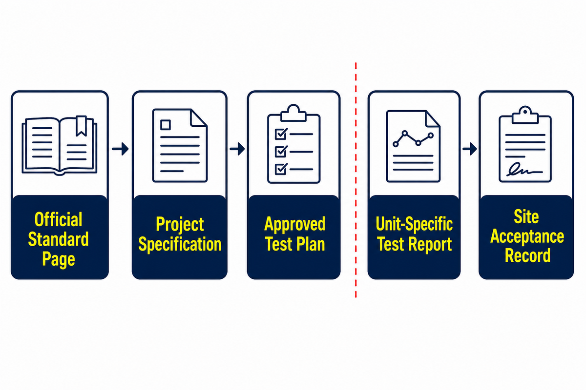
The standard citation is a map to a scope and method. It is not a free-standing certificate. The Scope-Before-Standard Rule asks four questions in order: Which edition? Which equipment category? Which clauses or tests were invoked? Which unit-specific record connects the standard to the supplied transformer?
| Evidence layer | What it can establish | What it cannot establish alone |
|---|---|---|
| Official standard page | Publication identity, edition, public scope, status, and sometimes test families. | Unseen clause content, acceptance values, or product conformity. |
| Project specification | The purchaser’s invoked requirements, options, and deliverables. | That the manufactured unit satisfied them. |
| Approved test plan | Which routine, type, or special tests will be performed and witnessed. | The final measured result. |
| Unit-specific test report | Measured results, method, equipment identity, conditions, and dispositions recorded for the tested unit. | Site installation quality or future operating condition. |
| Site acceptance/commissioning record | Defined installation and energization checks for the actual project. | Universal life or reliability guarantee. |
The official IEC 60076-1:2011 page describes the general scope for covered power transformers and lists exclusions. The official IEEE C57.12.90-2021 record identifies test families for covered liquid-immersed distribution, power, and regulating transformers, including resistance, ratio, no-load loss, excitation current, impedance, load loss, dielectric, temperature, short-circuit, and sound.
Those pages support a scope statement. They do not prove that a specific unit was tested, accepted, certified, or suitable for an installation. For a real order, connect the correct standard edition to the specification, drawing set, approved test plan, unit serial number, report, and acceptance record.
What Evidence Supports Distribution Transformer Reliability Across Its Lifecycle?
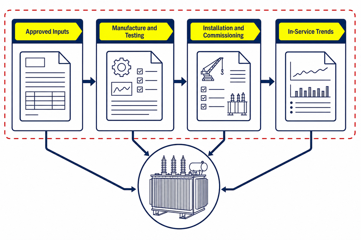
Evidence changes as a transformer moves from definition to service. A useful procurement or asset record keeps those stages connected instead of treating one certificate or report as universal proof. Each stage needs records tied to the same physical unit and project.
Distribution networks are changing with electrification and new sources and loads. Wind and solar, other renewable energy systems, batteries, and responsive demand can alter the surrounding power flow, but those network-operation topics do not change the basic evidence rule used here. Sustainable energy labels or a general renewable claim cannot establish transformer reliability. Equipment records still need to match the actual duty, voltage, current, thermal conditions, and governing requirements.
Before manufacture
The inputs are the approved single-line diagram, voltage and frequency, phase and connection, load basis, impedance requirement, environmental conditions, installation format, applicable standards, protection interface, drawings, tests, documentation, and acceptance criteria. Missing assumptions should be resolved before a rating becomes an order.
During manufacture and testing
The controlled record connects the approved design and serial number to material or process documentation where required, inspection records, calibrated test equipment, raw readings, corrected results, witness status, and dispositions. A pass/fail word without identity, method, conditions, and acceptance criteria is weak evidence.
At installation and commissioning
Site evidence covers physical identity, transport condition, approved drawings, clearances, grounding, terminations, accessories, settings, oil or insulation checks where applicable, pre-energization checks, and commissioning records. A factory test report cannot establish that the site installation matches the approved design.
In service
Operating history, loading, temperatures, alarms, inspections, maintenance, event records, and condition-test trends establish a time sequence. A single reading rarely proves cause. Qualified personnel should interpret trends against the unit design, service conditions, owner procedures, and previous baselines. This guide is not an energized-work instruction.
Monitoring is also an active development area. Patent publication US20240135280A1, for example, describes monitoring energy loss, capacity limit, and transformer health. A patent application signals technical interest; it does not prove adoption, legal validity, field performance, or that Toplit uses the described system.
Distribution Transformer vs Power Transformer: What Is the Practical Difference?
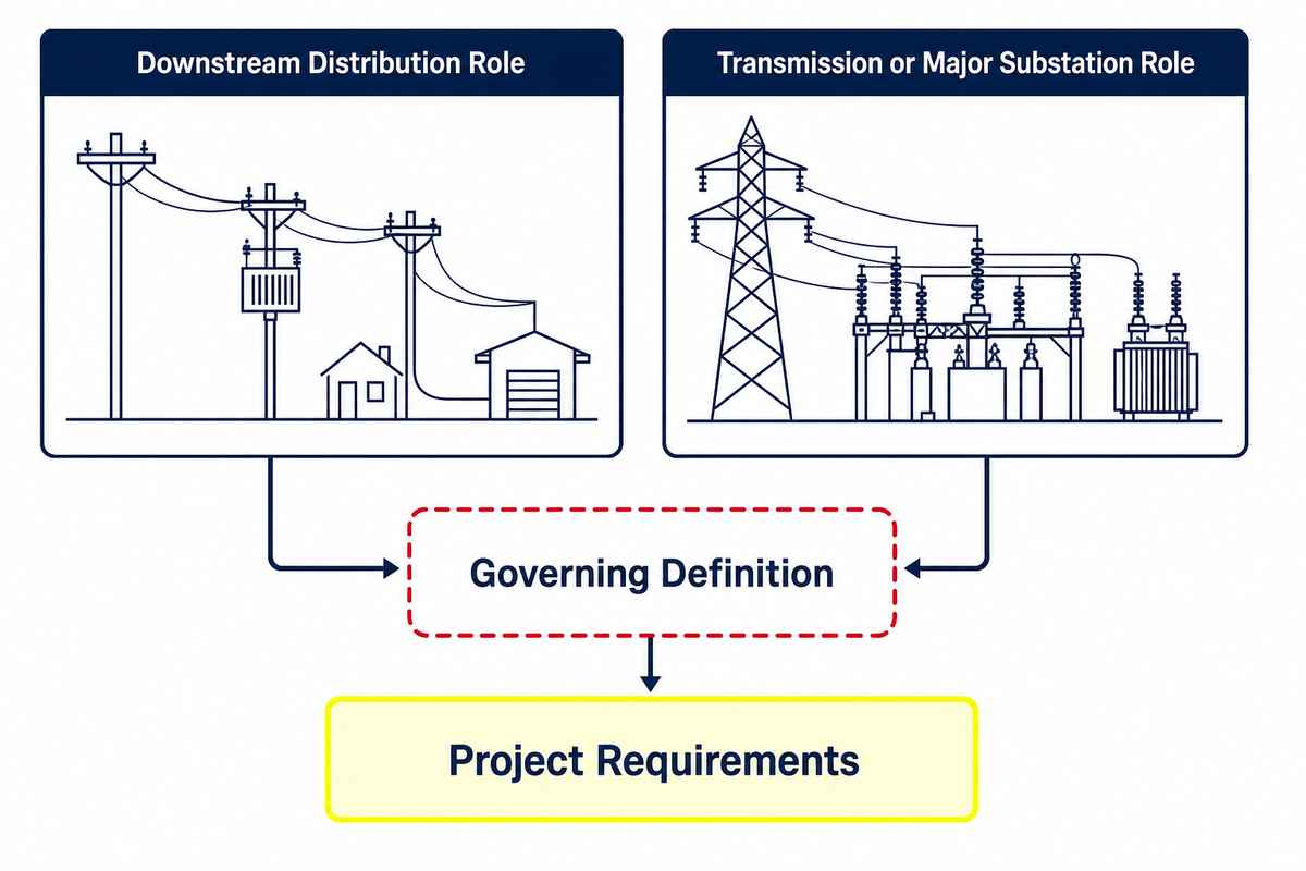
A distribution transformer usually serves the downstream delivery network and is expected to spend substantial time energized across a variable load profile. A power transformer label is commonly used for equipment at transmission or major substation boundaries. That operating-role distinction is more dependable than repeating one universal voltage or capacity cutoff.
In practice, utility terminology, standards, regulatory definitions, and supplier catalogues can draw the boundary differently. State the network role, voltages, kVA or MVA, phase, insulation/cooling family, mounting, duty, and governing requirements instead of relying on the label alone. When the question becomes commercial product selection, route it to the relevant solution page rather than expanding this guide into a duplicate catalogue.
Comparison check: a common mistake is forcing one worldwide cutoff because “power” and “distribution” labels vary by utility and application. In procurement, match the supplier description to IEC 60076, the project specification, rated voltage and capacity, and the unit test report.
Frequently Asked Questions
What is a distribution transformer?
A distribution transformer is a static AC device used near the load end of a power system to change voltage through electromagnetic induction. It commonly steps a distribution voltage down to a utilization voltage for local loads. The exact regulatory or standards classification depends on jurisdiction, rated voltage, frequency, capacity, construction, and exclusions, not only the product name. Its nameplate and project records supply the details that the broad definition can’t.
Why are distribution transformers rated in kVA instead of kW?
Transformer heating and electrical loading depend mainly on voltage and current, while the connected load’s power factor determines how much real power in kW is delivered. kVA expresses apparent power without assuming one power factor. That rating is still not a complete sizing decision: load profile, diversity, ambient conditions, harmonics, future duty, voltage regulation, protection, and the governing specification must also be checked for the actual project.
Do distribution transformers have no-load loss when nothing is connected?
Yes. When energized at its stated voltage and frequency, the transformer needs excitation and has core-related no-load loss even with little or no external load. Current-dependent load loss increases as load current rises. Annual energy analysis therefore needs both loss components, the energized schedule, applicable auxiliaries, and a realistic load profile, not just a rated-load efficiency figure.
What is the difference between no-load loss and load loss?
No-load loss accompanies core excitation. Load loss grows with winding current and related current-dependent effects. Certified comparisons require their stated test conditions.
Does an IEC or IEEE reference on the nameplate prove compliance?
No. A nameplate reference identifies a claimed design or test basis, not a complete proof package. Start with the applicable edition and confirm that the transformer category falls within its scope. Then connect the purchaser’s specification to the approved drawing and test plan, the exact model and serial number, the test method and conditions, raw or corrected results, acceptance criteria, witness status, and final disposition. If the jurisdiction requires a certificate, its issuer, scope, ownership, validity, and product identity must also match. A public IEC or IEEE page can confirm the publication and its general scope; it cannot certify the manufacturer, the factory, the order, or the installed unit.
Use the Right Page for the Next Question
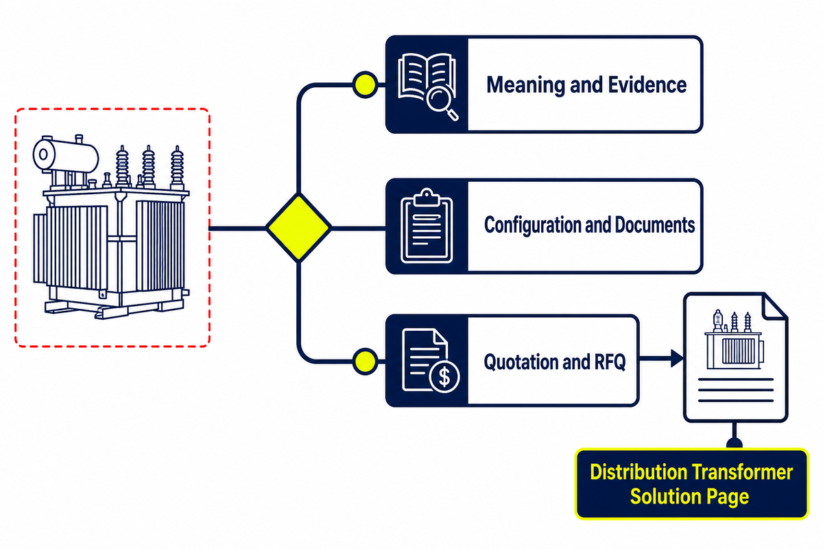
If your question is “What does this rating, loss figure, standard, or test record mean?”, stay with this guide and follow the evidence chain. If your question is “Which configuration fits my project, what documents can be supplied, or how do I request a quotation?”, continue to the distribution transformer options and project review page.
Have a project data sheet or transformer evidence question?
Share the system voltage, phase, load basis, installation format, applicable standard, and required documents. The team can route the question to the correct product and evidence review.
For publisher and company context, see About Us.
References & Sources
- 10 CFR 431.192 — Definitions, current electronic Code of Federal Regulations.
- 10 CFR 431.196 — Energy conservation standards and effective dates.
- U.S. Department of Energy — Distribution Transformer Test Procedure.
- U.S. Department of Energy — 2026 Request for Information on distribution-transformer standards.
- IEEE C57.12.90-2021 — Test Code for Liquid-Immersed Distribution, Power, and Regulating Transformers.
- IEC 60076-1:2011 — Power transformers, Part 1: General.
- Monash University — Transformers and transmission of electricity.
![Pad-Mounted Transformer: How It Works [2026 Guide]](https://toplit-transformer.com/wp-content/uploads/2026/08/pad-mounted-transformer-guide-featured-150x150.png)
![Single Phase Pad Mounted Transformer Guide [2026]](https://toplit-transformer.com/wp-content/uploads/2026/08/single-phase-pad-mounted-transformer-guide-featured-1-150x150.png)