Get in touch with Toplit Transformer Co., Ltd Company

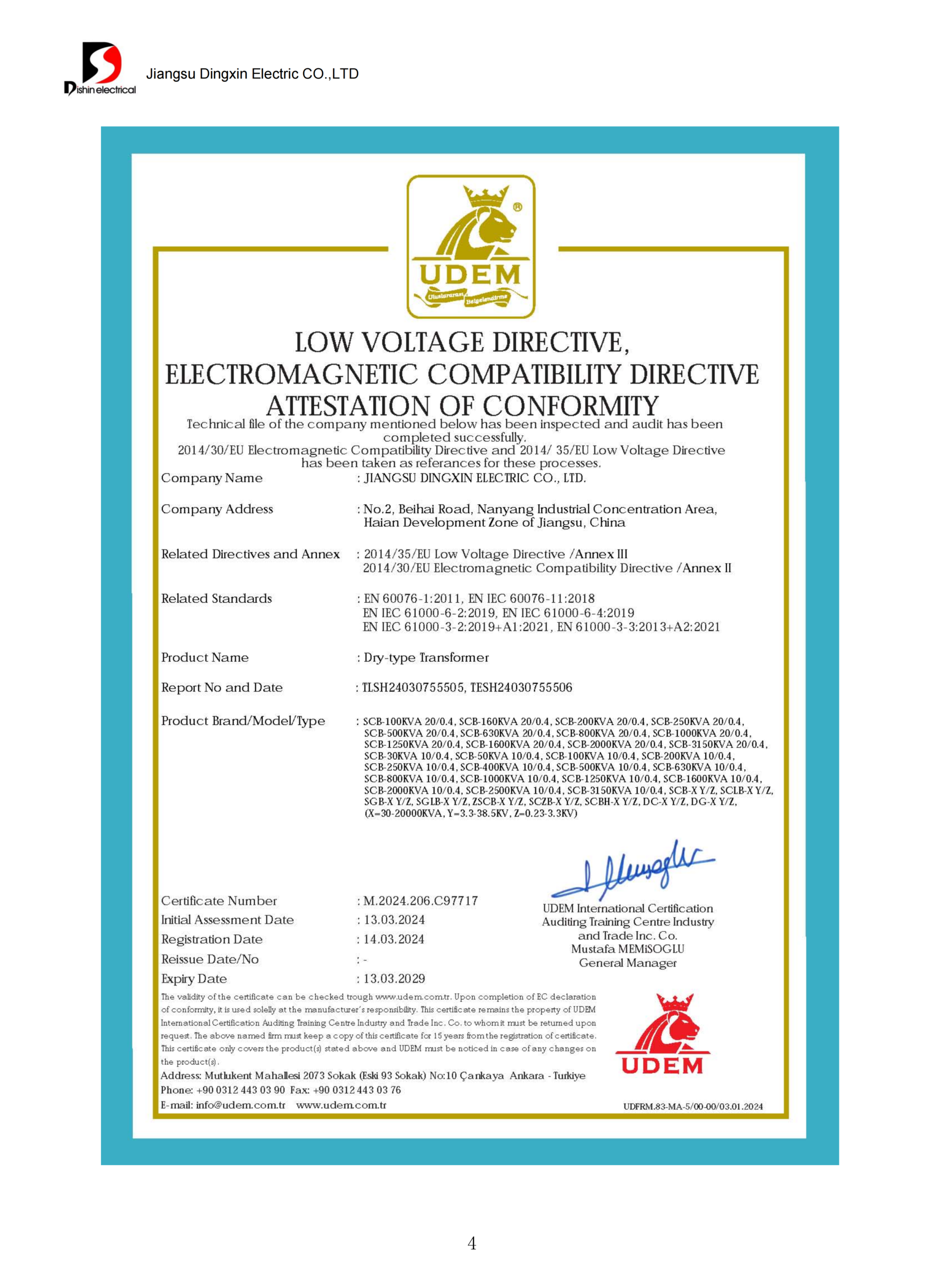
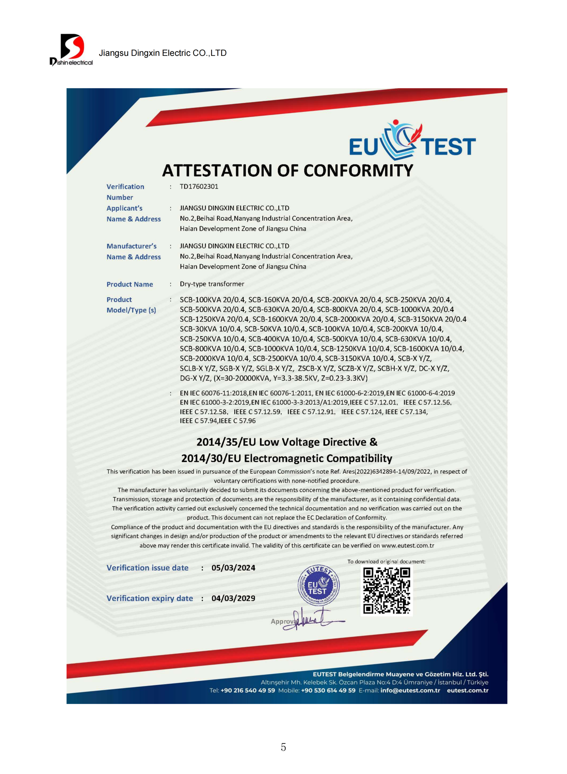
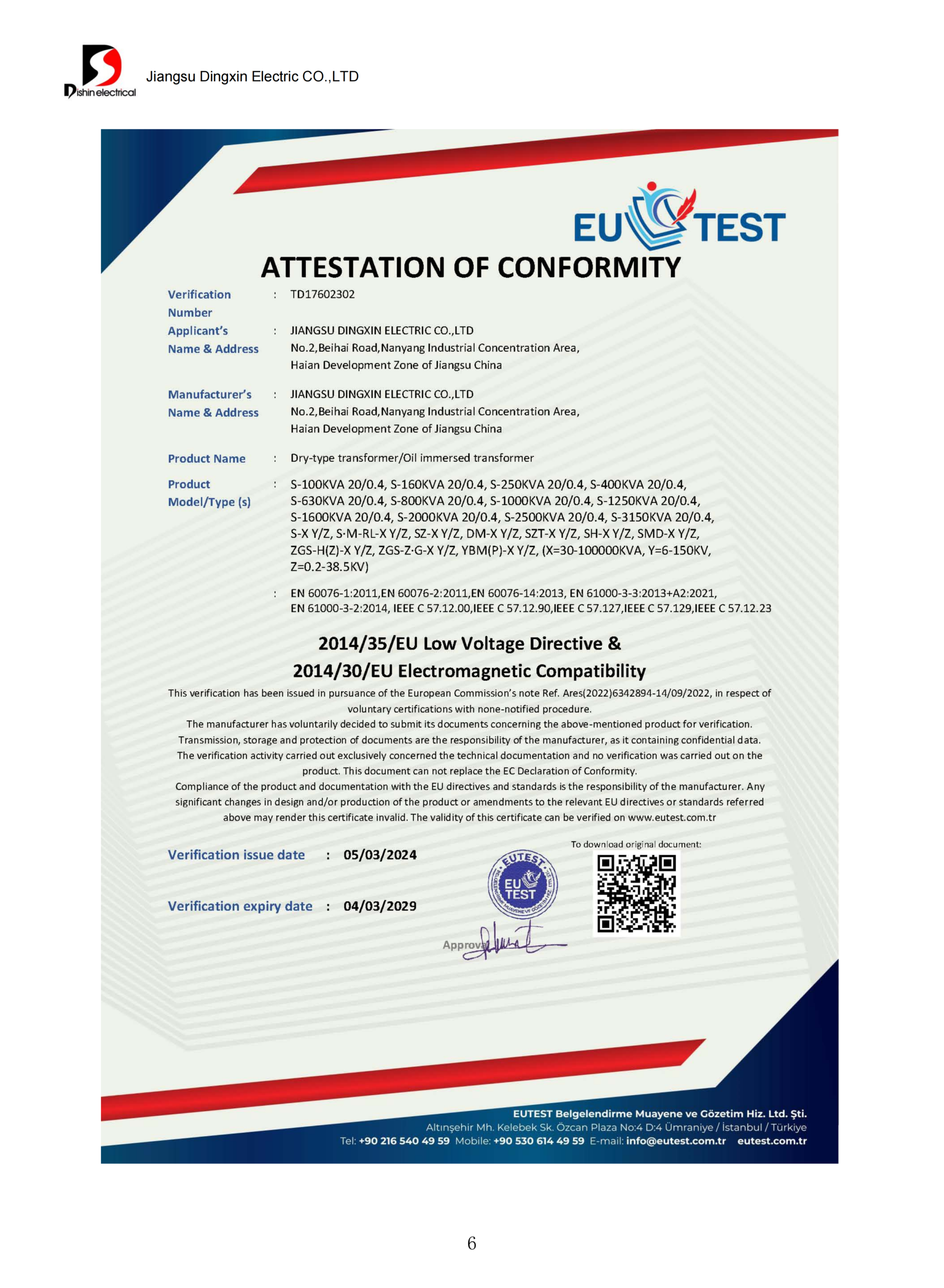
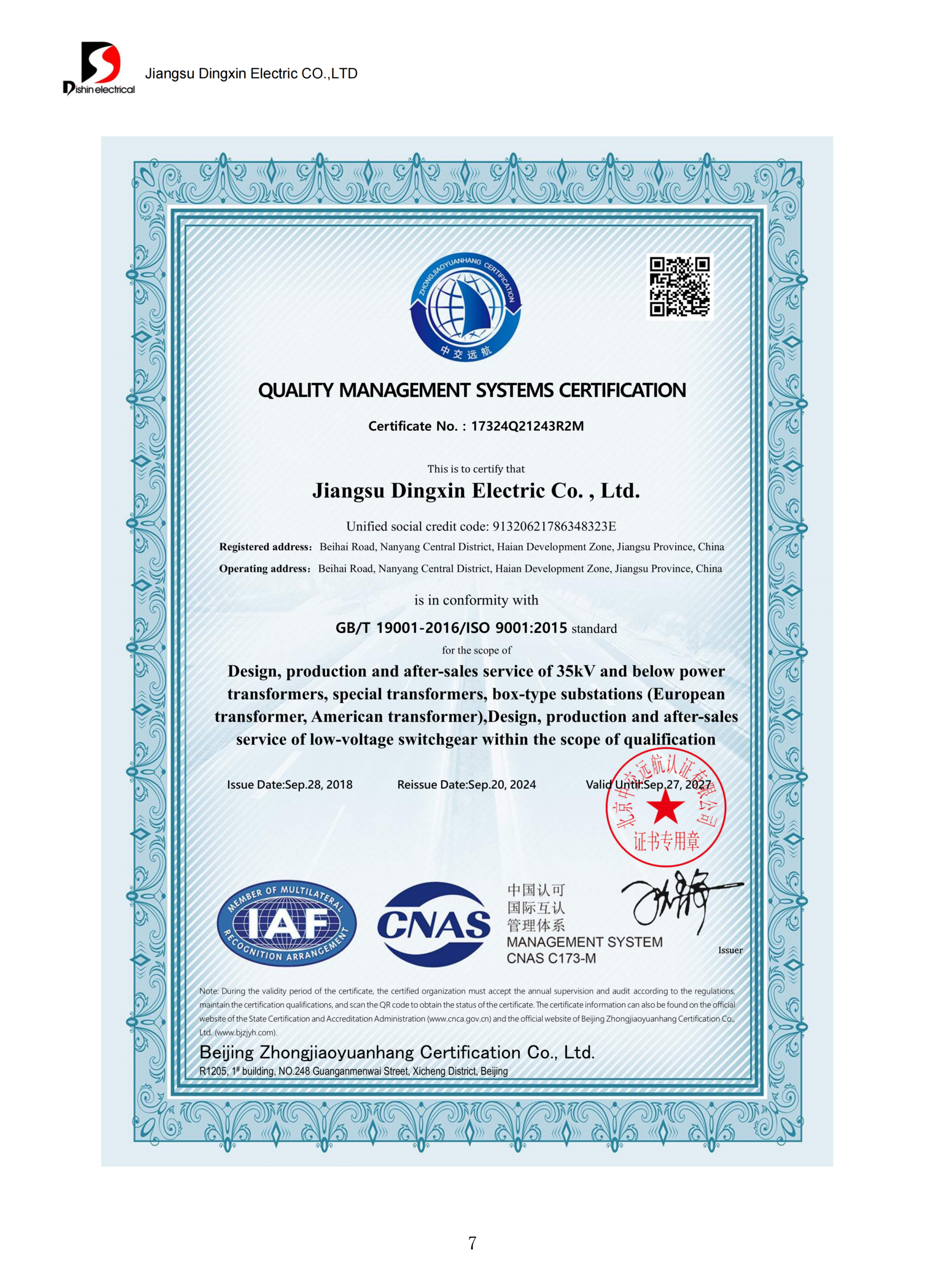
ISO 9001 Certified
Pad-Mounted Transformer
Pad Mounted Transformers, Designed and Tested to ANSI/IEEE, Specified in Six Decisions
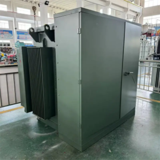
A pad mounted transformer is the ground level, locked steel enclosure that steps medium voltage underground distribution down to the utilization voltage your building actually runs on. Talite builds single-phase and three-phase padmount units, compact substations and prefabricated substations for export distribution networks, and publishes the specification logic instead of hiding it behind a quote form.
Request a Quote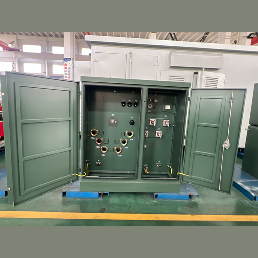
10–5000 kVA
Primary capacity envelope, matched to the US federal covered range for liquid-immersed units
≤34.5 kV / ≤600 V
Primary and secondary line voltage inside the same covered definition
ANSI/IEEE + CSA
Design and routine factory test basis, documented per unit
5 stage schedule
Quotation, drawing approval, production, ocean freight, customs
Why Underground Power Distribution Projects Specify Pad-Mounted Transformers Over Pole-Mounted Units
Once the medium voltage feeder goes underground, a pole-mounted transformer has nothing to hang on. A pad mounted transformer sits at grade on a concrete pad, takes cable in from below, and keeps every energized part behind a tamper-resistant enclosure that a member of the public can walk past without risk. Its secondary side hands the lower voltage straight into the building’s distribution equipment.
Underground distribution removes the overhead structure a pole-mounted unit needs, so the transformer becomes ground-mounted equipment by default.
Campuses, retail sites and residential areas put people within a few feet of the equipment, which is the reason for the locked, dead front enclosure. IEEE C57.12.28 is the enclosure integrity standard written for exactly that case, pad-mounted equipment above 600 V that the general public can reach.
Frequency is not a detail. US distribution runs at 60 Hz, and equipment built only for a 50 Hz market is not a drop-in substitute. Distribution transformers now sit on the critical path of the energization date, unlike the commodity bucket they used to occupy.
Buyers searching pad-mounted transformer vs pole-mounted transformer are usually past that choice already, because the civil design made it for them, and what they are really weighing is schedule risk and acceptance risk on a site the utility has to sign off before a ground mounted transformer is energized. More than half of the US distribution transformer fleet, roughly 40 million units, is already beyond its expected service life, and around 55 percent of in-service units are more than 33 years old, figures Wood Mackenzie put to POWER Magazine’s 2026 supply review. Replacement demand and new load now compete for the same qualified factory slots, which procurement teams feel as slipped dates rather than as a market statistic.
What This Changes in Your Schedule
- Treat the transformer as a long-lead item that gates the energization date, and start the specification before the civil design is frozen.
- Get the outline drawing early, because the pad, conduit stub-ups and clearance envelope are civil work that cannot start from a catalogue page.
- Lock the secondary voltage and connection before drawing approval. A change here after release restarts the production queue.
Talite Pad-Mounted & Substation Line: Comprehensive Power Distribution Solutions
Our comprehensive product families cover the entire range from a single residential service to complete packaged industrial substations. What separates them is not just size, but regional design standards (American vs. European styles) and how much of the medium voltage switching and low voltage distribution arrives inside one factory-tested enclosure. Buyers get this wrong more often than they get the kVA wrong, because these configurations look interchangeable in a catalogue but behave very differently on site.
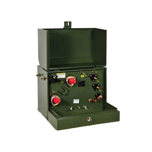
Single-Phase Pad-Mounted Transformers
- Standard ratings 25, 37.5, 50, 75, 100 and 167 kVA
- Secondary 240/120 V, loop feed or radial feed
- Dead front, tamper-resistant enclosure
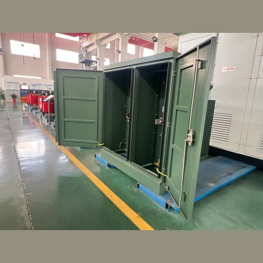
Three-Phase Pad-Mounted Distribution Transformers
- Standard ratings 45 through 2500 kVA, larger by project build
- Secondary 208Y/120 V, 480Y/277 V or 600Y/347 V
- Loadbreak or non-loadbreak primary terminations
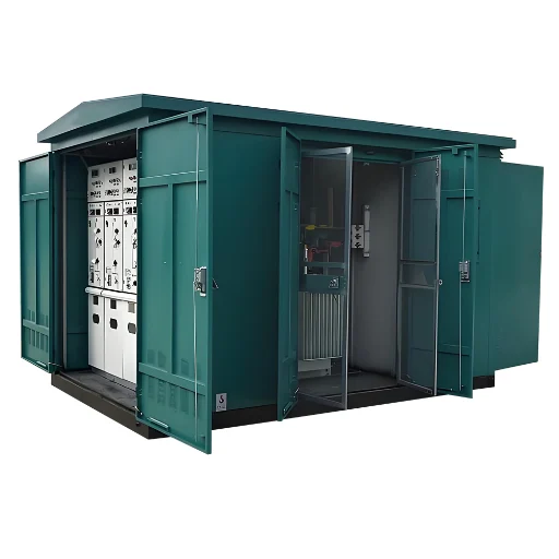
Compact Substations
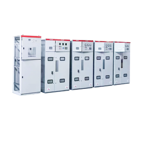
- One shell holding the substation transformer, the medium voltage switchgear and the low voltage panel.
- Ring main or radial incoming, the two compact substation types most often quoted
- Factory assembled and tested as a compact secondary substation
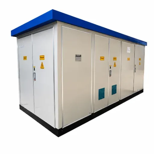
Prefabricated Substations
- Skid mounted or contained within a shipping container, this substation keeps site construction to a minimum. A foundation is all that is really needed on site.
- A prefabricated substation ships as a modular package: high-voltage switchgear, transformer and low-voltage switchgear.
- Circuit breakers, protection and metering integrated before shipment
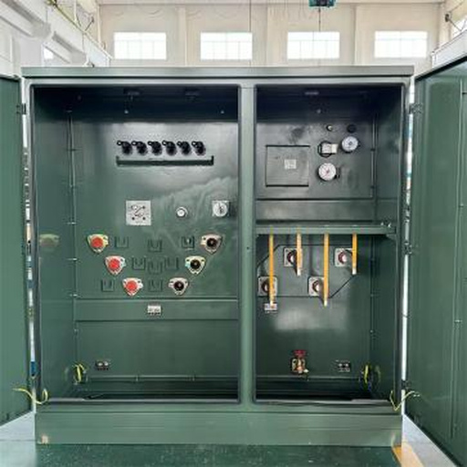
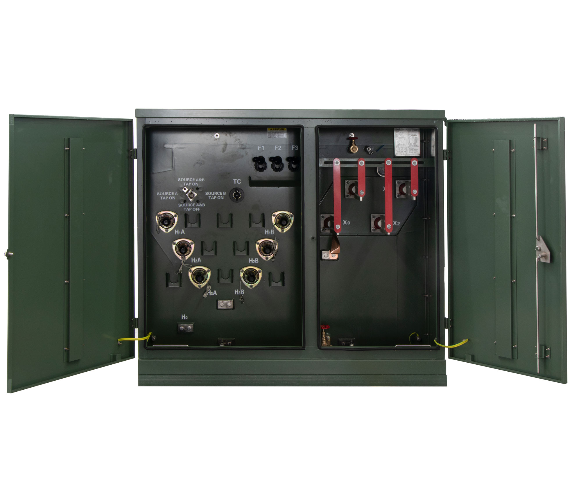
American Style Pad Mounted Transformer
- Combines transformer, load switch, and fuses in one tank
- Compact footprint ideal for residential and public spaces
- Tamper-resistant, dead-front design for maximum safety
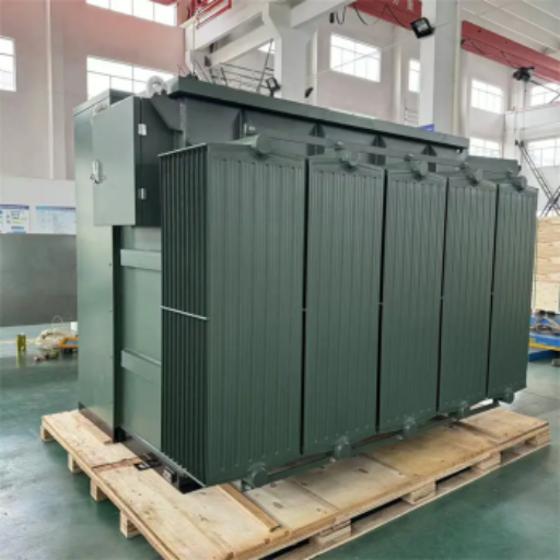
Combined Substation Transformer
- Integrates transformer and switchgear into a single unit
- Reduces on-site installation time and civil engineering costs
- Perfect for renewable energy (solar/wind) and industrial parks
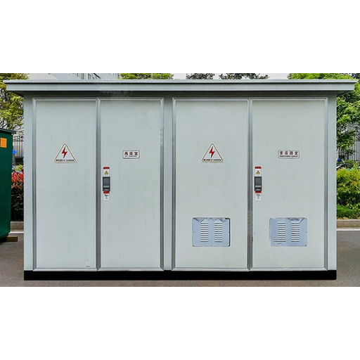
European Style Compact Substation
- Independent compartments for HV, transformer, and LV sections
- Excellent heat dissipation and environmental adaptability
- Widely utilized in urban distribution networks and commercial centers
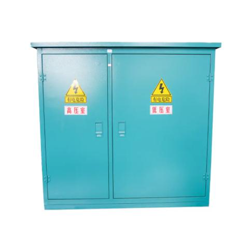
Prefabricated Compact Substation
- Fully factory-assembled and tested for rapid deployment
- Flexible configurations for complex distribution requirements
- Weather-resistant, high-strength structure for rugged outdoor use
Our padmount units of the compartmental type are covered by IEEE C57.12.34, with liquid-immersed transformer requirements under IEEE C57.12.00, and enclosure integrity per IEEE C57.12.28. Additionally, European-style and combined substations align with relevant IEC standards. These documents define the rigorous terms every Talite drawing and factory test report uses, ensuring your project complies with global public standards.
Choosing the Right Configuration Without a Site Visit
One service, one building, and no medium voltage switching on your side of the meter: a classic single-phase or three-phase pad-mounted unit is the right call.
You own the ring and must sectionalize it, or require independent compartments for maintenance: this pushes the decision toward a European-style compact substation.
Thin civil budget or remote installation on a strict schedule: a prefabricated or combined substation keeps site construction to a minimum. A foundation is all that is really needed.
Consider regional standards and footprint limits: American styles integrate everything into one tank for smaller footprints, while European styles use separate compartments for safety isolation.
Pad Mounted Transformer Sizes: kVA Ratings, Voltage Classes and Pad Dimensions
The ranges for pad-mounted transformer sizes are finite. Standard kVA steps, standard primary voltage classes and the insulation level tied to each class are fixed by the ANSI and IEEE tables, and quoting outside them costs money and weeks with nothing gained. Anyone hunting 3 phase pad mounted transformer sizes should start from the table below rather than from a competitor’s catalogue page.
| Primary voltage class | Typical system voltage | Basic impulse insulation level | Where it usually appears |
|---|---|---|---|
| 15 kV | 12470GrdY/7200 V, 13200GrdY/7620 V, 13800GrdY/7970 V | 95 kV | Most commercial and light industrial services |
| 25 kV | 24940GrdY/14400 V | 125 kV or 150 kV | Longer rural and campus feeders |
| 35 kV | 34500GrdY/19920 V | 150 kV or 200 kV | Upper limit of the federal covered definition |
The DOE covered boundary, and the two ways a spec quietly falls outside it
US federal energy conservation rules do not reach every liquid-filled transformer on a pad. 10 CFR 431.192 sets four conditions at once, and a unit has to satisfy all four before the efficiency standard applies to it.
| Parameter | Inside the covered definition | Outside it |
|---|---|---|
| Input line voltage | 34.5 kV or less | Above 34.5 kV |
| Output line voltage | 600 V or less | Above 600 V |
| Frequency | Rated for 60 Hz | 50 Hz only |
| Capacity, liquid-immersed | 10 kVA to 5000 kVA | Below 10 kVA or above 5000 kVA |
| Capacity, dry-type | 15 kVA to 5000 kVA | Below 15 kVA or above 5000 kVA |
| Tap range | Under 20 percent | 20 percent or more, excluded by name |
| Impedance | Inside the table 1 normal band | Special-impedance units, excluded by name |
The ceiling moved from 2500 kVA to 5000 kVA for liquid-immersed units in April 2024, and a great deal of published material still prints the old number. Contrary to how most specification sheets read, the two rows at the bottom matter more than the capacity row, because a buyer can trigger them by accident and give up the efficiency they thought they were buying.
Two specification traps worth knowing before the requisition is written
A transformer with a tap range of 20 percent or more is one of thirteen types named as excluded. A conventional padmount at plus or minus two 2.5 percent taps sits well inside the limit, whereas a wide-tap request pushes the unit out of coverage.
Special-impedance units are excluded by name too, judged against the normal band in the rule’s table 1, which for liquid-immersed three-phase units between 750 and 5000 kVA runs 5.0 to 7.5 percent. Asking for an impedance outside that band gives up the efficiency guarantee you thought you were buying.
Eleven further exclusions cover autotransformer, drive isolation, grounding, machine-tool control, nonventilated, rectifier, regulating, sealed, testing, uninterruptible power supply and welding types.
How pad dimensions actually get set
Pad size comes from the unit outline drawing plus the clearance your serving utility requires, and those two inputs arrive from different places. That is why compact substation dimensions published by any vendor are a starting point rather than an answer. Talite issues the outline and foundation drawing during drawing approval, so the civil contractor works from the real footprint of the unit being built for you.
Pad Mount Transformer Configuration: The 6 Decision Spec Path
Most requisitions arrive with a kVA number and nothing else, which means the supplier guesses six things on your behalf. Below is the order Talite works in, and each step carries the cost of getting it wrong. Anyone assembling 3 phase pad mounted transformer specifications for a bid package can lift this sequence directly.
| Step | Decision | What Sets It | Cost of Getting It Wrong |
|---|---|---|---|
| 1 | Load profile to kVA | Connected load, demand factor, power factor, growth allowance | Oversizing raises no-load loss for 30 years; undersizing forces early replacement |
| 2 | Primary voltage class to insulation level | Utility system voltage and grounding | Wrong insulation level fails utility acceptance at commissioning |
| 3 | Secondary voltage and connection | Building distribution, 208Y/120 V or 480Y/277 V | A change after drawing release restarts the production queue |
| 4 | Loop feed or radial feed | Whether the site must stay energized during an upstream fault | Radial on a site that needed loop feed turns one cable fault into a full outage |
| 5 | Dead front or live front | Public exposure and utility standard | Live front where the utility mandates dead front is a rejected installation |
| 6 | Dielectric fluid and enclosure | Fire separation distance, coastal exposure, indoor or vault use | Mineral oil where a less-flammable liquid was required blocks the occupancy permit |
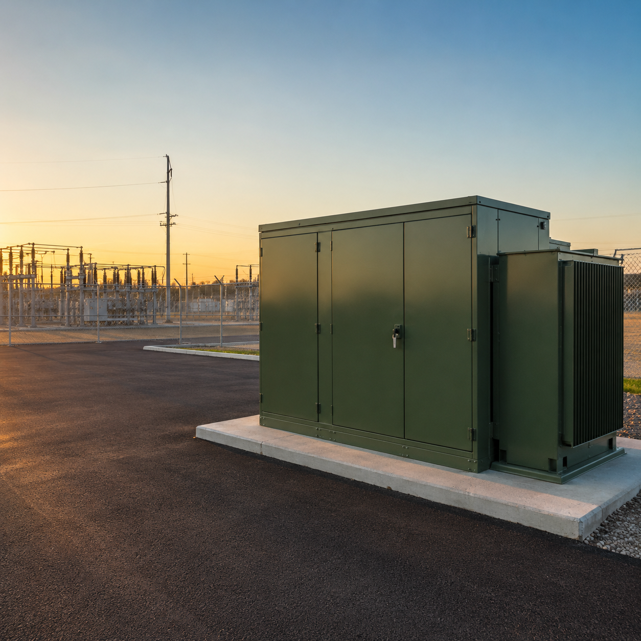
Step 6 is where fluid choice stops being a preference. Under NFPA 70 Section 450.23, a listed less-flammable liquid has a fire point of not less than 300 °C, and that listing is what allows the reduced separation distances a tight site depends on. Mineral oil remains the lower cost answer whenever the separation distance is available, so the trade-off is site geometry against unit price rather than quality against price.
ANSI-Style and IEC-Style Pad-Mounted Transformer Specifications Are Not the Same Machine
An American-style pad mounted utility transformer follows the ANSI and IEEE system: compartmental enclosure, bushing wells and loadbreak elbows, bayonet fuses, dead front as the default. A European-style unit follows IEC practice with ring main switchgear and a different terminal arrangement, which is the structural reason the two are not interchangeable on a US utility feeder. Buyers who assume a datasheet conversion is enough discover the mismatch at the acceptance inspection.
What to Put in the Requisition
- State the standard family first, ANSI/IEEE or IEC, before any other parameter, because everything downstream follows from it.
- Name the fuse arrangement you expect, bayonet with a backup current limiting fuse or expulsion type, rather than leaving it to the factory.
- Say whether the enclosure has to meet the coastal environment requirements of IEEE C57.12.29 instead of the standard C57.12.28 basis.
- Confirm against the serving utility’s own standard before release, since a utility standard overrides a manufacturer catalogue every time.
Where Pad Mount Transformers Get Deployed: Applications by Load Profile
Load profile, not industry label, decides the rating and the configuration. Two sites drawing the same peak kilowatts need different transformers when one runs flat around the clock and the other peaks for four hours. Specifying from the industry name rather than from the curve is the mistake that stays expensive for 30 years.
| Load profile | Typical capacity band | Configuration that usually follows |
|---|---|---|
| Data centers and critical infrastructure | 1000–2500 kVA and above | Loop feed, dead front, redundant units, high continuous loading |
| Battery energy storage and solar | 500–2500 kVA | Bidirectional duty, wide daily load swing, outdoor coastal exposure common |
| Electric vehicle charging | 75–2500 kVA | Sharp peaks, low average utilization, oversizing risk is highest here |
| Commercial and industrial buildings | 150–1500 kVA | Radial feed acceptable, 480Y/277 V secondary common |
| Utility residential areas | 25–167 kVA single-phase | Loop feed, standardized to the utility’s own stock specification |
Electric vehicle charging is the row that catches project teams. Federal efficiency values are certified at 50 percent of rated load under 10 CFR 431.196, and per-unit load is defined in the rule as the fraction of rated load, so a heavily oversized unit spends its whole life away from the point where its efficiency was measured. That is the trade-off behind every generous growth allowance, and Talite will flag it in writing rather than quietly quote the larger unit.
Standards, Testing and US Compliance: What Talite Can Document
Import rejection is driven by test documentation, leak handling and warranty response far more often than by electrical performance, and utility acceptance of a non-listed source is the gate that decides many purchases. An overseas manufacturer cannot borrow a domestic supplier’s credibility, so this section separates what Talite can put in writing from what it cannot. Everything below is either a document that ships with the unit or a rule you can read yourself.
Design and Test Basis
ANSI and IEEE: C57.12.00 for general requirements, C57.12.34 for three-phase compartmental padmount units, C57.12.28 for enclosure integrity, and C57.12.26 for the compartmental construction including the penta-head bolt arrangement.
CSA C227.4 for units where Canadian rating applies to the same construction.
NEMA TR-1 for audible sound level limits, published by NEMA.
Current editions of all of these are available through the ANSI webstore, so nothing here rests on our summary of them.
US Efficiency Compliance and Who Actually Carries It
Two facts decide how an imported unit gets treated. Efficiency requirements in 10 CFR 431.196 apply to any transformer inside the covered definition regardless of where it was built, and US energy conservation law counts importing as manufacturing, which puts the certification and record-keeping duty on the importer of record. Buyers who assume the overseas factory carries that duty find the liability sitting on their own side at audit.
A Scheduled Step to Design Around
The efficiency table steps up on 23 April 2029, and that revision is the first to carry three-phase liquid-immersed rows above 2500 kVA, including 3750 kVA and 5000 kVA. A unit specified today for a 30 year life will spend most of it under the later standard.


Routine and Type Tests
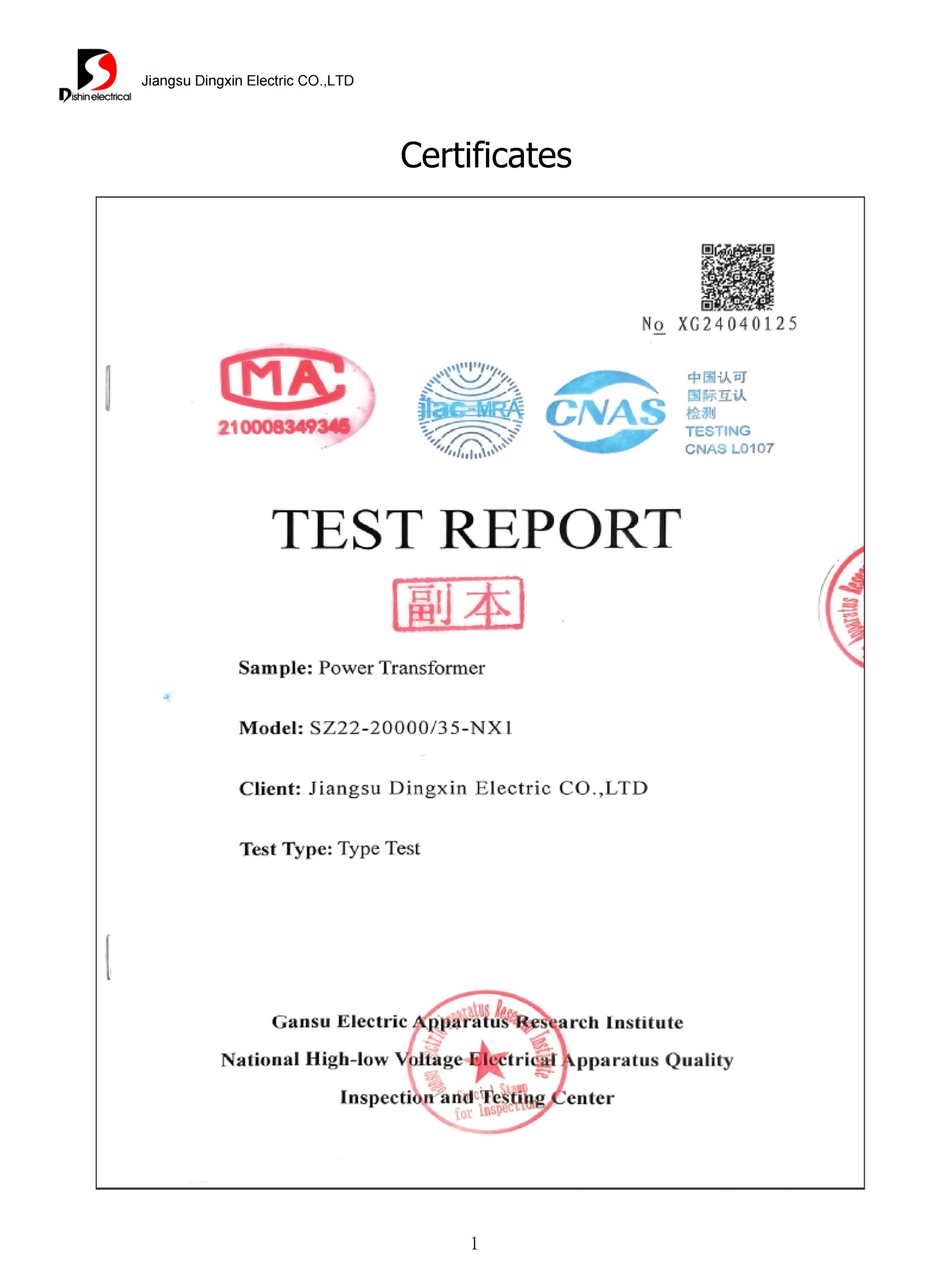
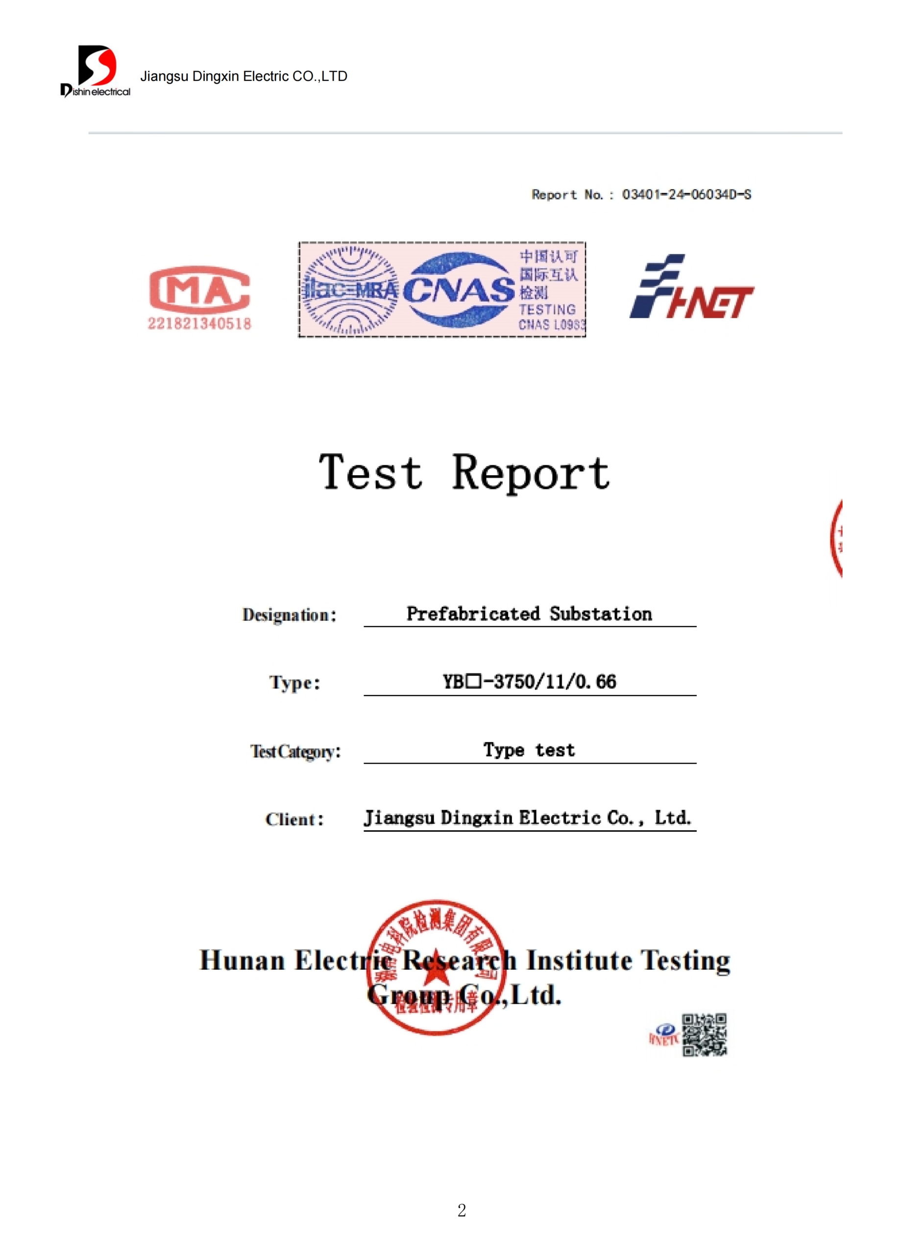
Routine, on every unit: turns ratio, no-load loss, load loss, impedance, insulation resistance, and applied and induced voltage withstand.
Type or special, by project: temperature rise, impulse and short-circuit withstand.
Tolerances follow ANSI C57.12.00, which allows 10 percent on single-unit no-load loss and 6 percent on total loss, tightening to 2 percent on the average of a multi-unit order.
Never accept unspecified or typical loss values in place of measured ones, and do not let a schedule squeeze delete the factory acceptance test.
Documents That Ship With the Unit
Certified factory test report carrying the measured no-load and load loss values for that serial number
Outline and foundation drawing, internal assembly drawing, and nameplate drawing.
Material certificates for core steel, winding conductor and dielectric fluid.
Packing list, handling instructions and the commissioning check sheet
Transparency Statement
Manufacturing location: units are built in Hai’an, Nantong, Jiangsu, China.
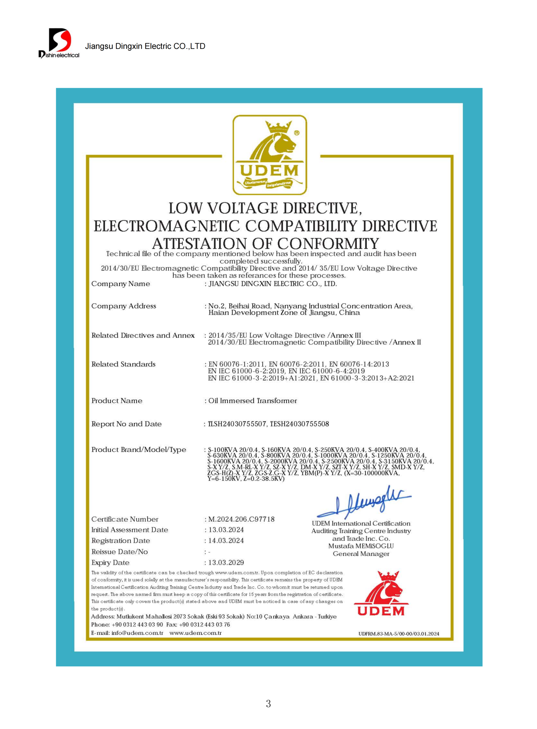
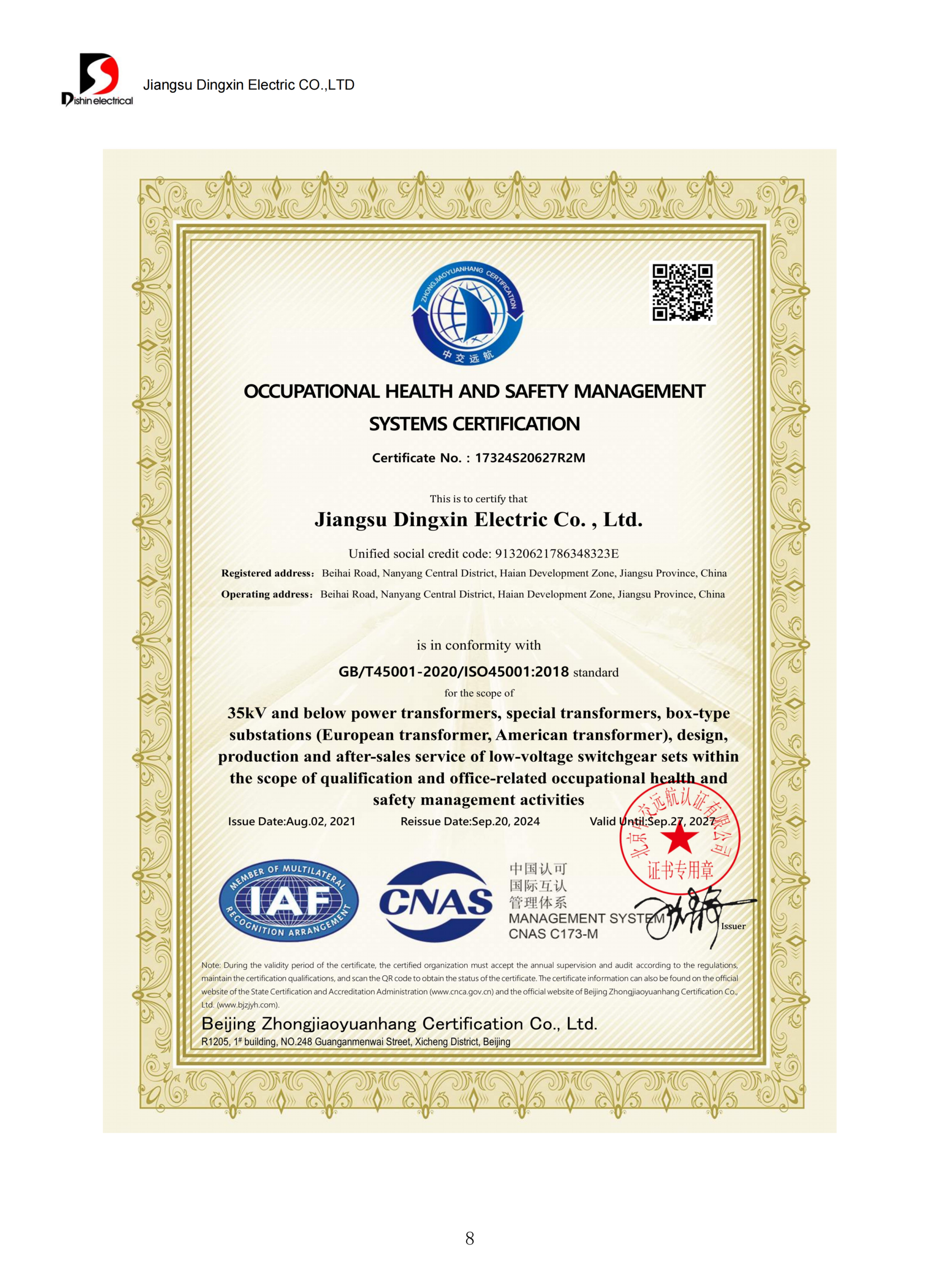
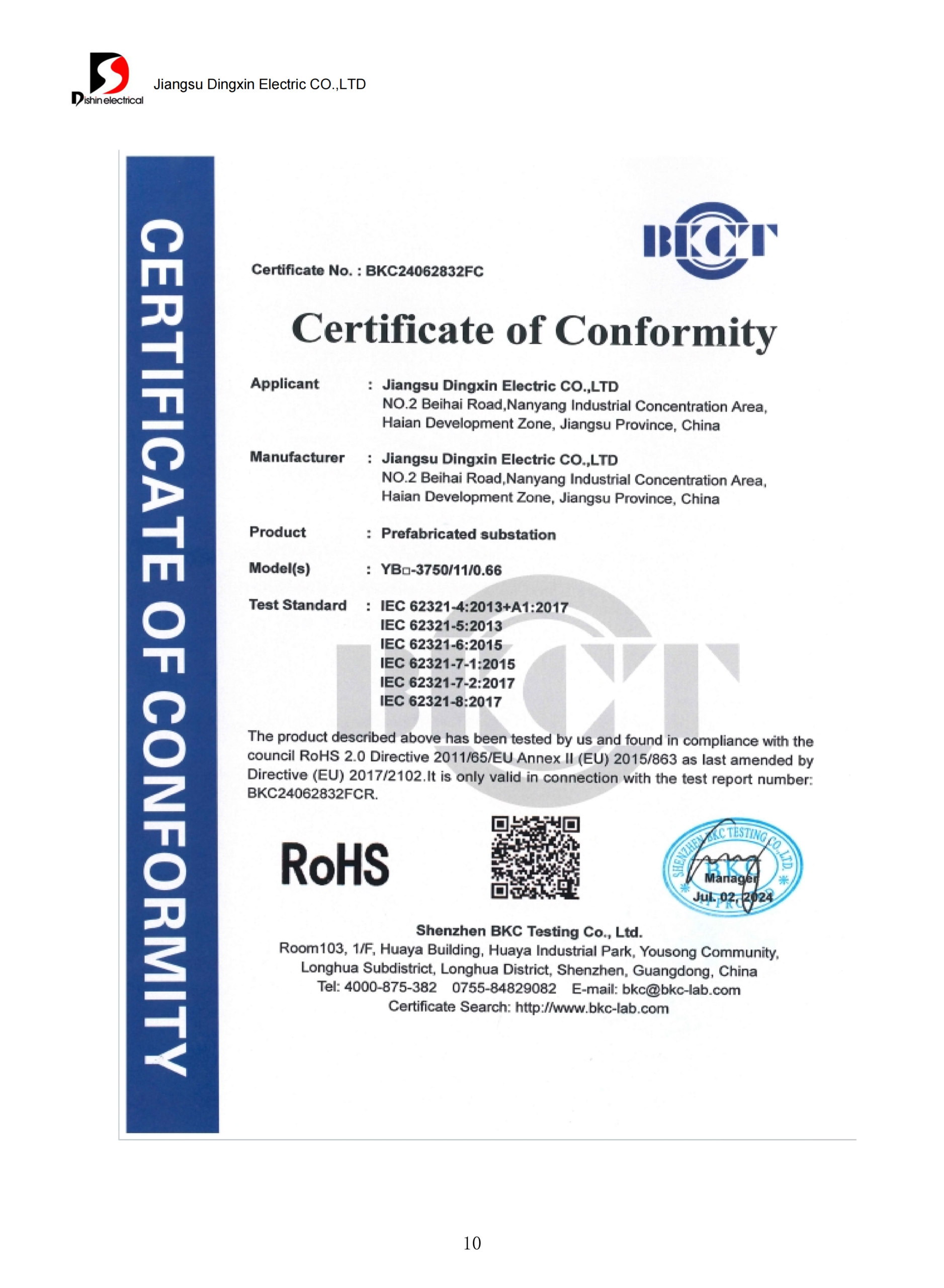
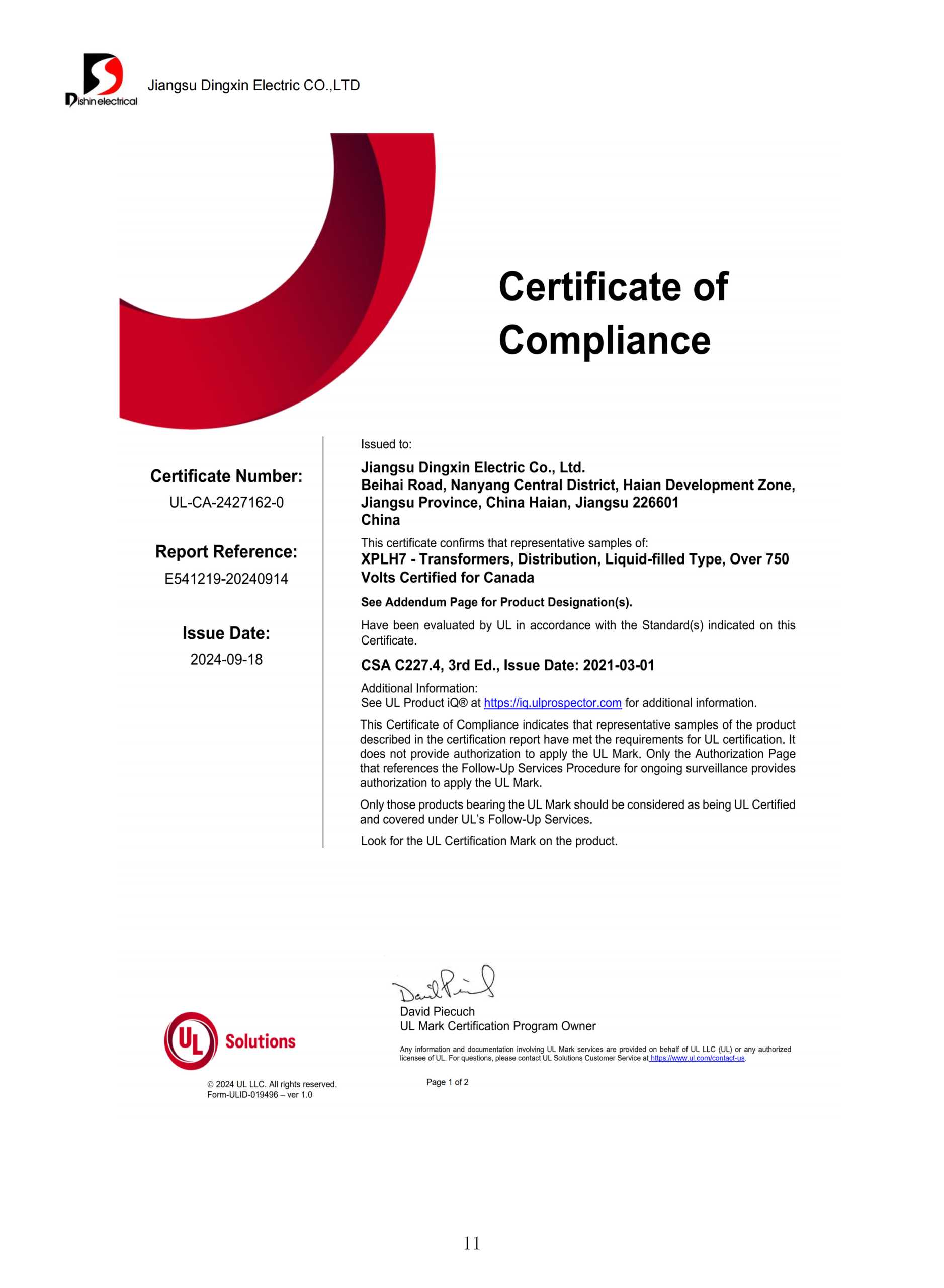
Conformity basis: Talite states design and factory test conformity to the standards listed above. We will not claim third-party listing or US federal efficiency certification on this page, and will not until the certificates are issued in our own name and can be shown to you.
Federally Funded Projects
Domestic sourcing requirements apply at project level on federally assisted work, and rules on entities of concern can narrow eligibility further. Confirm with your funding authority before the requisition, and read this line as a prompt to check rather than as legal advice.
“The measured no-load loss on a certified test report is the number a buyer can hold us to for the next 30 years. That is the honest version of a capability claim, and it is why we would rather publish the test list than an adjective.”
×
![Zoomed Certificate]()
Pad-Mounted Transformer Engineering Tools
Pad Mounted Transformer Sizing Calculator
Enter the demand load your electrical engineer has calculated, and this returns the next standard kVA step, the loading point you will actually run at, and whether that point sits where the federal efficiency figure was measured.
Access Calculator
DOE Covered Transformer Checker: 10 CFR 431.192
Federal efficiency rules do not reach every liquid-filled transformer on a pad. Four conditions have to hold at once, and two ordinary-looking spec choices push a unit outside coverage by name. Enter your parameters to see which side of the line your spec falls on, and why.
Check Compliance
Transformer Loss Capitalization Bid Evaluator
The cheapest quotation is routinely the most expensive transformer. Enter the price and the measured losses from each bid and this returns the evaluated total, which is what utility specifications actually compare. Default capitalization factors are the published values from the Idaho Falls Power pad-mounted transformer specification; replace them with your own the moment you have them.
Evaluate Bids
Pad Mount Transformer RFQ Parameter Builder
Twelve items make a quotation binding. Anything you leave out gets assumed by the factory, and assumptions are what drawing revisions are made of. Fill these in and copy the finished block straight into your enquiry.
Build RFQ
FAQ: Pad Mounted Transformer Sizing, Lead Time and Specification
Start from connected load, apply the demand factor for the building type, divide by power factor, then add a growth allowance checked against the real load curve rather than taken from a rule of thumb. Round up to the next standard kVA step rather than to a custom rating, because non-standard ratings add weeks without adding capability. Aim to land in the upper half of the loading range instead of doubling capacity: federal efficiency values are certified at 50 percent of rated load, an oversized unit pays no-load loss every hour of every year it stays in service, and the serving utility has to sign the rating off before release.
Published figures run from around 30 weeks for the distribution class as a whole to two years or more for utility-specified units, because those numbers count different equipment. Ask any supplier to break the quotation into quotation response, drawing approval, production, ocean freight and customs. A single number without that structure cannot be held to, and drawing approval is usually the one stage a project team can genuinely shorten.
Twelve items make a quotation binding: kVA rating, primary voltage and grounding, secondary voltage and connection, frequency, phase, impedance requirement, tap arrangement, loop or radial feed, dead front or live front, dielectric fluid type, enclosure and coastal requirement, and the applicable standard family. Anything missing gets assumed by the factory, and assumptions are what drawing revisions are made of.
Single-phase units follow 25, 37.5, 50, 75, 100 and 167 kVA. Three-phase units run 45, 75, 112.5, 150, 225, 300, 500, 750, 1000, 1500, 2000 and 2500 kVA, with larger ratings available as a project build. Non-standard ratings add cost and weeks without adding capability.
Radial feed brings one cable in and costs less wherever a single outage is tolerable. Loop feed puts the unit on a loop, so an upstream cable fault can be isolated without dropping your site. Specify loop feed whenever the utility standard calls for it, or whenever the site cannot accept a full outage.
Dead front uses bushing wells and separable loadbreak elbows, with no exposed energized parts, and it is the default wherever the public can reach the equipment. Live front leaves the primary connections accessible behind the barrier. Most US utilities mandate dead front, so confirm the utility standard before pricing either one.
Most are liquid-immersed, on mineral oil or a less-flammable fluid; dry-type units exist but suit indoor use. Less-flammable liquids permit reduced fire separation under NEC Article 450, so site geometry usually decides.
While NEC Article 450 spells out how to house liquid-filled units when placed outdoors and Article 110 discusses working clearances, power equipment located ahead of the service point is often outside the NEC and is governed instead by the serving electric utility’s own standards. Nail down ownership beyond the service point early in the project.
There isn’t a generic national standard for a 25 foot clearance around a transformer. It’s dictated by the serving utility’s standards, by NEC rules driven by the dielectric fluid’s fire performance, and by local regulations, all of which differ with the fluid in the tank and with the construction of whatever stands next to it. Obtain your transformer’s specific clearance requirement from your electric utility in writing before the placement on the concrete pad is fixed.

![Single Phase Pad Mounted Transformer Guide [2026]](https://toplit-transformer.com/wp-content/uploads/2026/08/single-phase-pad-mounted-transformer-guide-featured-1-150x150.png)