Get in touch with Toplit Transformer Co., Ltd Company

Marine Port Infrastructure Transformer Solutions
A marine port infrastructure transformer must align with the utility connection, berth and terminal load profile, shore-to-ship interface, protection philosophy, and coastal installation conditions. Talite reviews those boundaries before mapping the project to a transformer, port substation, switchgear, monitoring, and document package.
- Port-side voltage matching
- Shore power and terminal loads
- Project-specific transformer and substation configuration
Port-Side Solution Scope
Power transformer platform
110 kV to 220 kV, with a documented range from 5 MVA to 100 MVA
Distribution transformer platform
Oil-immersed and dry-type configurations for 35 kV and below
Port substation equipment
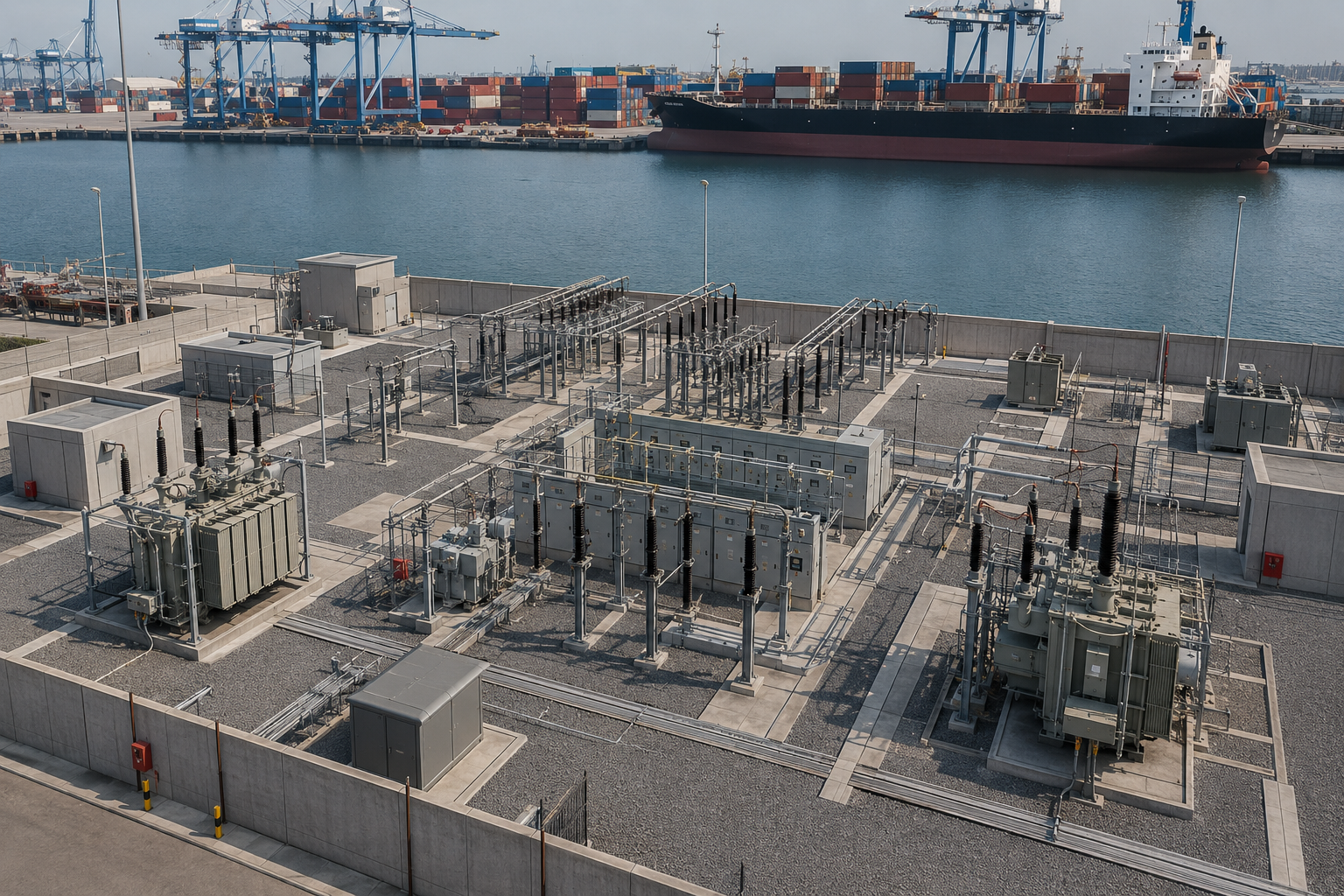
Prefabricated substations plus high- and low-voltage distribution equipment
Frequency review
50 Hz or 60 Hz project requirements
System inputs
Utility, load, shore-to-ship, protection, environment, and expansion data
Engineering output
Configuration, drawings, test scope, project-record list, and commercial quotation
Why the scope stays open at this stage
A nameplate range is not a substitute for the port load study. Selecting from capacity alone risks a mismatch with berth concurrency, utility limits, coastal conditions, or the shore-to-ship interface, so Talite confirms the electrical baseline against the wider IEC/IEEE 80005-1 system scope before issuing a project-specific configuration.
System Architecture
Port Electrification Transformer and Substation Configuration
We configure the equipment boundary around the electrical system that the port authority, terminal operator, utility, and engineering contractor have defined. This keeps a transformer selection from being isolated from grid capacity, power demand, short-circuit duty, protection coordination, and future electrification loads.

Equipment and load inputs
- Incoming and required secondary voltage
- Connected load, diversified demand, and berth concurrency
- Motor starting current for cranes, pumps, and workshop equipment
- Harmonic spectrum from converters, chargers, and variable-speed drives
- Redundancy, overload philosophy, and future expansion stages
- Preferred dry-type, oil-immersed, pad-mounted, or prefabricated-substation arrangement
Utility and protection inputs
- Available utility service and hosting capacity
- Required feeder, substation, or upstream grid upgrades
- Shoreside electricity boundaries and interactions with utility power grids
- Fault level, protection zones, selectivity, and earthing philosophy
- Power-quality limits, voltage regulation, and permissible disturbances
- Reliability criteria, backup strategy, and restoration sequence
- Utility, regulator, port, and vessel-interface responsibilities
Product Resources
Talite product platforms available for the review
Utility transformer solutions
Oil-immersed distribution transformers
Cast-resin dry-type transformers
Pad-mounted transformers
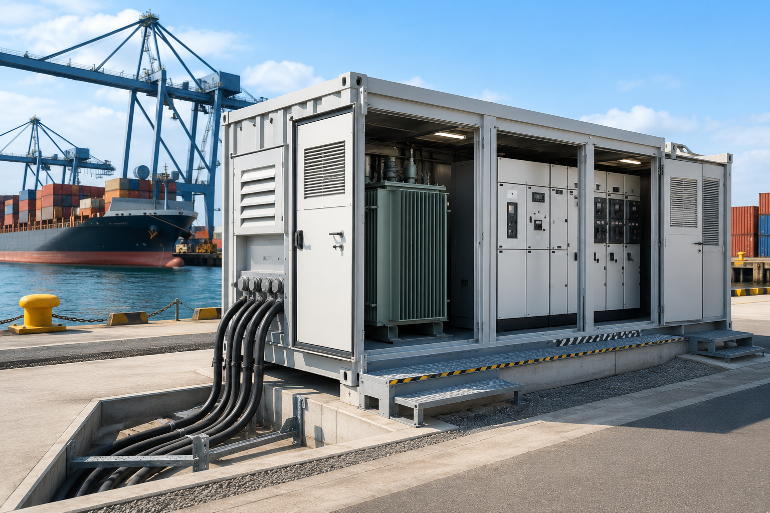
Prefabricated substations
6 kV to 35 kV high-voltage switchgear
Low-voltage switchgear and control cabinets
Grid Planning
Power Utilities & Grid Distribution
Connect port electrification planning with the upstream utility and grid-distribution scope. Review utility interfaces, substations, feeders, protection, resilience, and expansion requirements beyond the port boundary.
Explore Power Utilities & Grid Distribution
Infrastructure Scope
Port electrical system interface review
Power-system planning
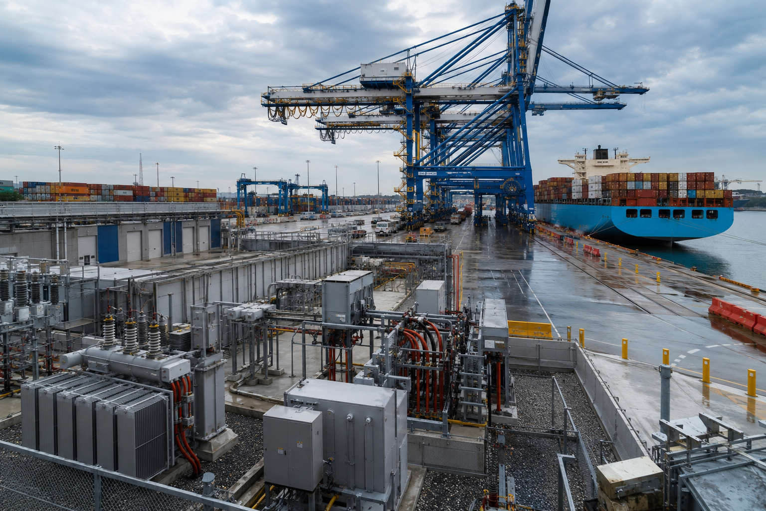
Power-system planning starts at the electrical grid and public utility interface, then moves through power delivery, port power distribution, and the terminal loads. Port authorities, terminal operators, the utility, and each project stakeholder should agree grid upgrades, operational priorities, and the responsibility split for port facilities and port equipment.
Shore power connection
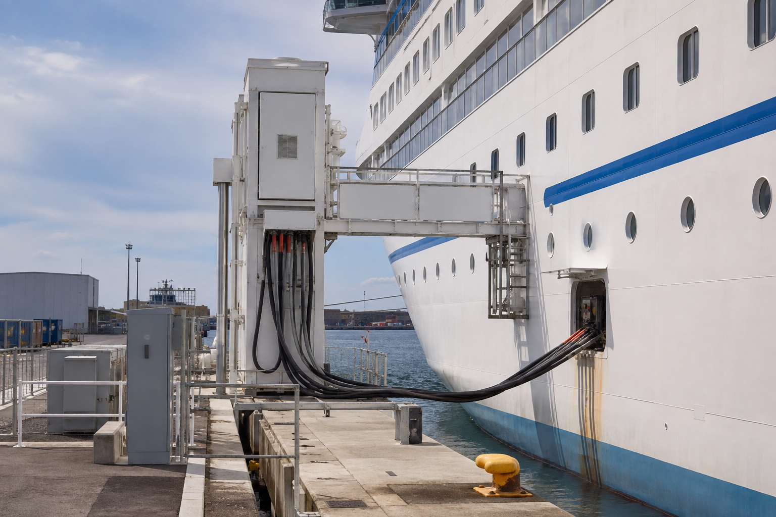
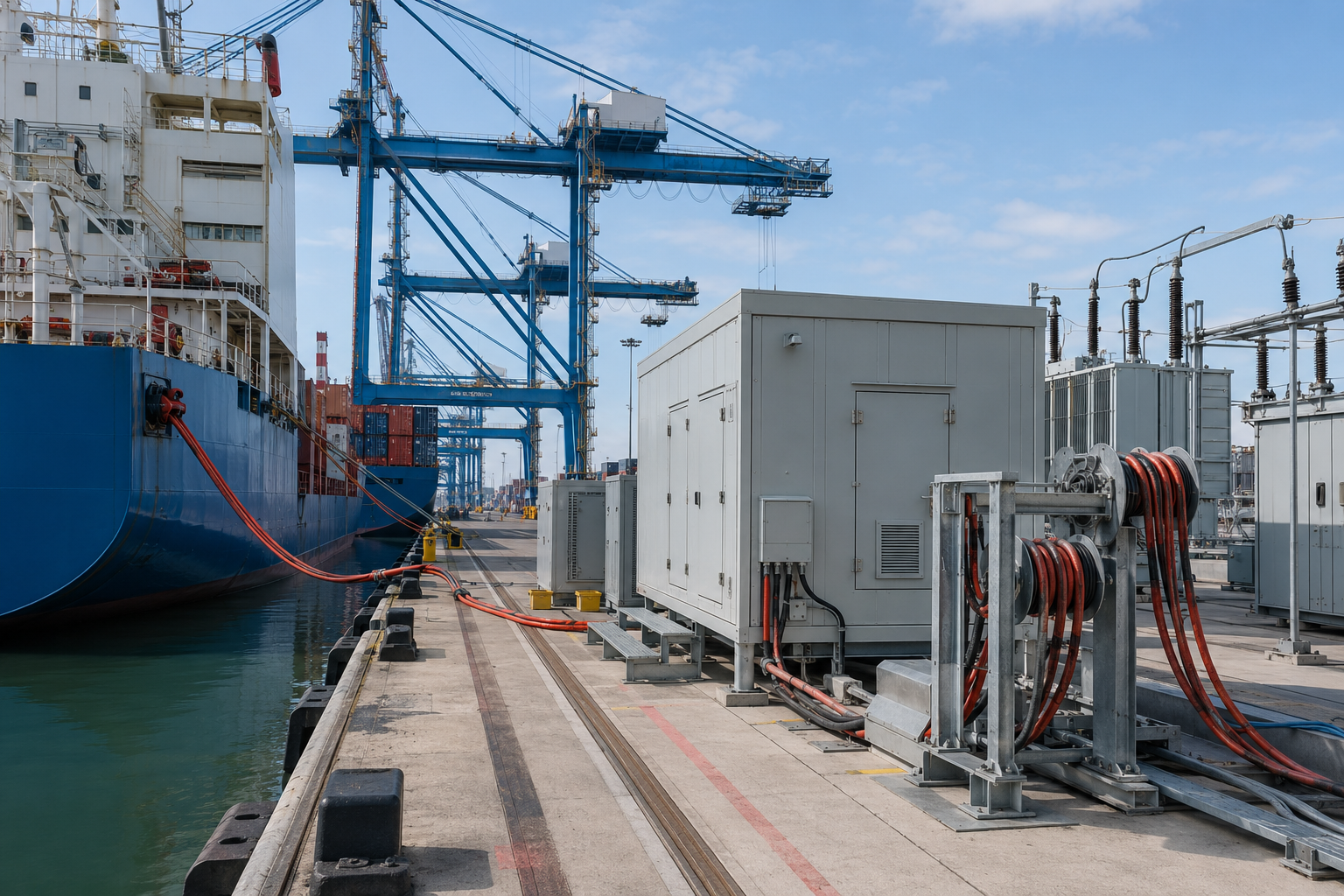
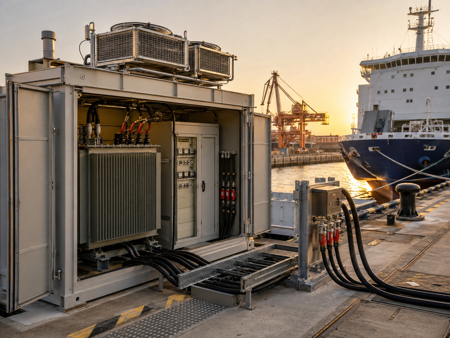
Onshore power supply systems are also described as shore-side electricity (SSE), alternative maritime power, or OPS systems. OPS infrastructure must connect to OPS receiving equipment on a ship at berth through a defined shore power connection, AC power interface, control sequence, and electrical isolation arrangement.
Energy-transition context
Ports electrify cargo operations and replace a berthed vessel’s auxiliary diesel engine and diesel fuel use with power from the shore to support air quality, emission reduction, and decarbonization objectives. That sustainability case still depends on the electricity source, vessel adoption, utilization, and the environmental impact of the local grid.
Operating context and public objectives
Vessels and shipboard power
A cruise ship, container vessel, or passenger vessel can connect to onshore electricity only through a compatible shore-to-ship power interface. The shore power system must align electric power, vessel load, operating sequence, and the approved connection standard.
Seaport modernization
Shore power infrastructure, electric cargo equipment, and other port energy projects change power delivery across the port area. Port activity, terminal growth, and electric equipment plans should be phased together so the investment does not strand capacity.
Maritime transport outcomes
A cleaner power supply can improve air quality around ports and reduce local air pollution or greenhouse gas emissions when the electricity mix and vessel use support that result. Energy transition technology, zero-emission goals, and the natural environment provide context, while the transformer study remains an electric power distribution and electric power quality task.
System boundary
IEC/IEEE 80005-1 places transformers and reactors inside a wider high-voltage shore connection that also includes shore distribution, interface equipment, frequency conversion where required, ship distribution, control, monitoring, interlocking, and power management. Equipment selection therefore follows the port and vessel interface study; it does not replace it.
Evidence before equipment selection
IEC/IEEE 80005-1 defines a wider system because voltage, frequency, protection, control, and vessel compatibility interact across the interface. Talite engineers use that named boundary with the project load data to reduce interface risk and configure the transformer and substation; a transformer is not a substitute for the system study.
Applications
Port Loads and Onshore Power Supply Applications
A port infrastructure transformer cannot be selected from total kilowatts alone. Load timing, starting behavior, voltage and frequency, harmonics, operating continuity, and physical interface conditions change the configuration.
01
Shore power at berth
Provide vessel types, berth schedules, average and peak demand, receiving voltage, 50 Hz or 60 Hz compatibility, connection arrangement, earthing, monitoring, safety circuits, and interlocking sequence. An onshore power supply transformer and any frequency converter belong in the architecture only when the utility and vessel interfaces require them.
02
Ship-to-shore and rubber-tired gantry cranes
Crane drives combine rapid load changes, regenerative operation, starting duty, and power-electronics harmonics. We use the drive data and duty cycle to review impedance, voltage regulation, thermal loading, and protection coordination.
03
Refrigerated container racks
Reefer loads create a distributed electrical load that can grow with yard throughput and seasonal cargo patterns. Separate installed outlets, expected simultaneity, feeder arrangement, and expansion capacity in the load list.
04
Electric vehicle and cargo charging
A charger for electric drayage, terminal tractors, and electrifying cargo handling equipment can add large coincident demand and harmonic current. Charging schedules, converter topology, electric vehicle charging network plans, battery energy storage systems, diversity, energy management, and future fleet size belong in the transformer study.
05
Workshops, pumps, and auxiliary systems
Maintenance shops, dock pumps, lighting, security systems, and building loads have different continuity and motor-starting requirements. Separating essential from nonessential loads helps define redundancy and recovery priorities.
06
Microgrids and local generation
A port microgrid, renewable energy source, battery energy storage system, or backup generator changes operating modes and protection behavior. Islanding, resynchronization, reverse power, grounding, and utility agreements must be settled before equipment ratings are frozen.
Maximum-demand discipline
EMSA guidance recommends estimating maximum demand from the port operating profile, ship types, and the number of vessels calling concurrently. A connected-load sum is a starting point; the procurement value comes from the agreed operating scenario, while the IEC/IEEE 80005-1 interface scope keeps the transformer inside the complete system review.
Marine electrical systems without a generic label
A marine transformer or other marine power solution still has to fit the port’s voltage, frequency, protection, power electronics, corrosion resistance, and safe-operation criteria. We treat marine electrical safety and efficient power distribution as engineering requirements for the installed marine electrical systems, not as an unqualified product badge.
Transformer for Port-Side Marine Applications
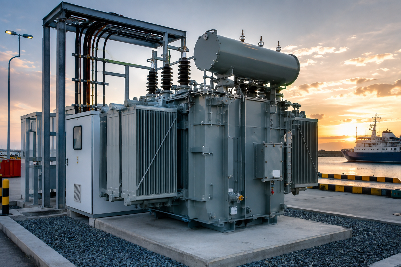
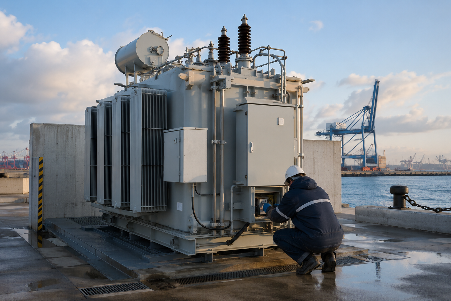
Coastal duty is a set of measurable installation conditions, not a single “marine-grade” label. We request the environmental and site data that drive enclosure, coating, insulation, cooling, foundation, access, and maintenance decisions.
Marine environment
Salt, condensation, heat, spray, pollutants, vibration, and limited access create a harsh marine setting for electrical equipment. Corrosion protection, complete electrical isolation where required by the approved system, enclosure sealing, cable interfaces, and maintenance provisions must be evaluated together.
Reliability and serviceability
Reliability engineering compares failure modes, critical loads, redundancy, monitoring, spare parts, recovery time, and safe access. Stable power needs a practical inspection and repair route, rather than maximum equipment complexity.
Input
Project data to provide
Configuration consequence
Atmospheric corrosivity
Distance from salt water, airborne salinity, humidity, condensation, pollutants, and the project corrosivity category
Coating system, material selection, hardware, sealing, inspection, and maintenance plan
Flood and storm surge
Design flood elevation, storm-surge level, drainage, wave or splash exposure, and required recovery objective
Equipment elevation, foundation, cable entry, barriers, access, and replacement strategy
Wind and structural hazards
Site wind, seismic, tsunami, atmospheric ice, and jurisdictional load criteria
Enclosure, anchorage, foundation, radiator support, and external component restraint
Temperature and ventilation
Minimum and maximum ambient, solar gain, enclosure ventilation, heat rejection, and room temperature
Cooling method, temperature rise, derating, fan duty, and alarm settings
Water and wildfire exposure
Fire scenario, combustible materials, smoke, ember, water spray, and firefighting access
Transformer type, separation, fire protection, drainage, containment, and emergency isolation
Maintenance and design life
Inspection access, outage windows, spares philosophy, lifting routes, service resources, and target asset life
Layout, accessories, monitoring, replaceable components, service records, and lifecycle plan
Electrical Specifications and Selection Inputs
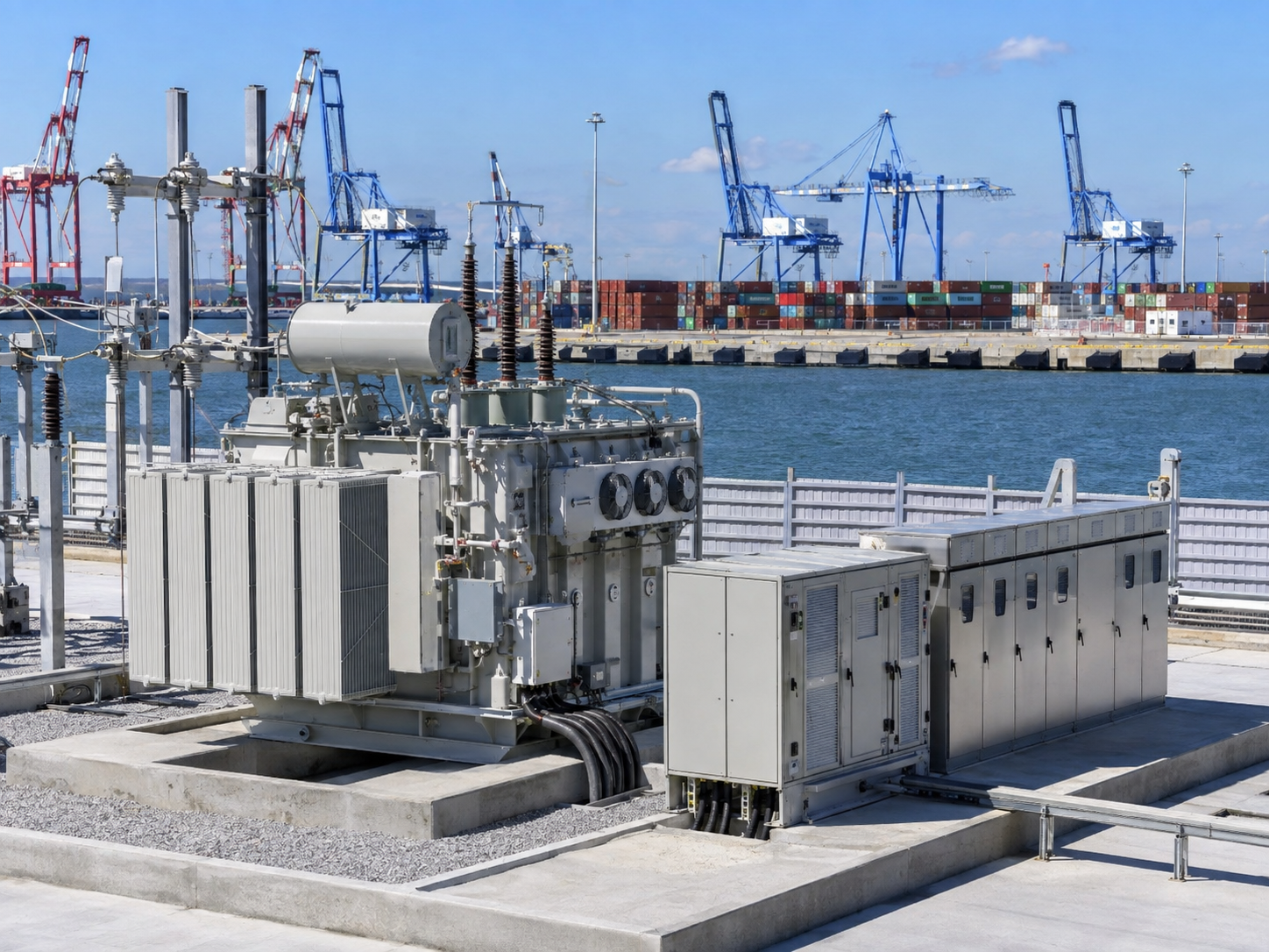
Talite’s documented product platform gives the engineering team a starting range. The final port infrastructure transformer rating, vector group, impedance, tap range, insulation level, enclosure, cooling, accessories, and tests are confirmed against the approved single-line diagram and project specification.
Platform: 110 kV to 220 kV
Validation: Utility service, system studies, insulation coordination, and switching arrangement
Platform: 5 MVA to 100 MVA
Validation: Diversified demand, contingency, load growth, cooling, and transport limits
Platform: 35 kV and below, extending to 31,500 kVA
Validation: Installation, containment, fire strategy, losses, impedance, and maintenance access
Platform: 20,000 kVA at 35 kV
Validation: Project voltage ratio, vector group, tap range, fault level, accessories, and test scope
Platform: 3,150 kVA at 35 kV
Validation: Indoor or enclosed duty, ventilation, fire strategy, temperature rise, and enclosure
Platform: 63–1,600 kVA on 6–10 kV, 50 Hz networks
Validation: Port load, local frequency, switchgear, protection, enclosure, footprint, and expansion
Platform: 6 kV to 35 kV
Validation: Rated voltage, short-circuit duty, bus arrangement, protection, interlocks, and arc strategy
Platform: 50 Hz or 60 Hz project review
Validation: Utility and vessel compatibility plus the need for frequency conversion
- Primary and secondary voltage
- Rated power and load profile
- Frequency and phase
- Vector group and earthing
- Impedance and fault level
- Tap range and regulation method
- Insulation level and surge environment
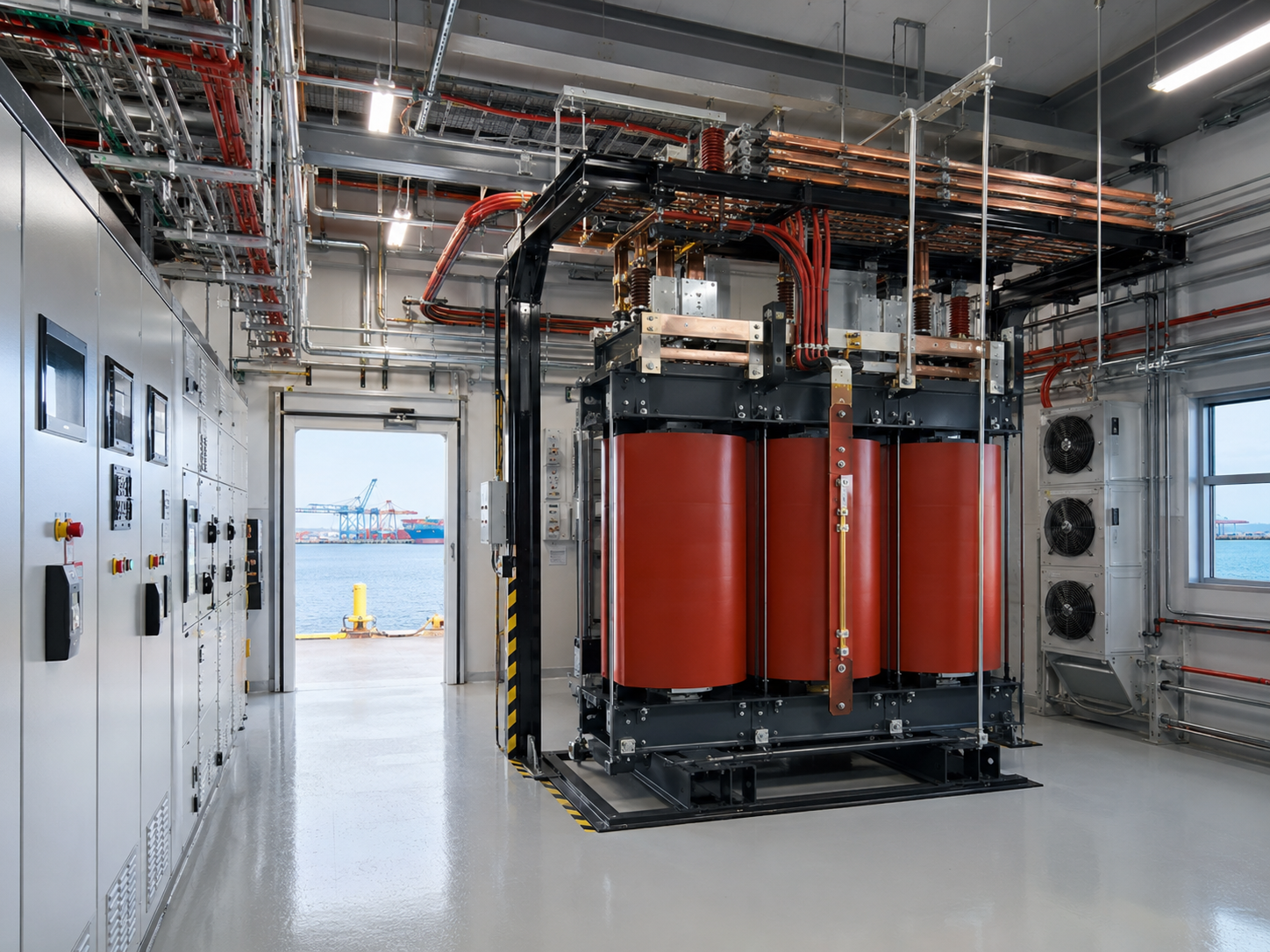
- Cooling and temperature-rise limits
- Harmonic and rectifier duty
- Enclosure and corrosion protection
- Monitoring, alarms, and communications
- Applicable standards, tests, drawings, and reports
- Low voltage and medium-voltage boundaries
Pricing and Project Lead-Time Framework
Price follows the electrical rating, voltage combination, insulation system, winding and core design, cooling, enclosure, accessories, monitoring, tests, project records, quantity, raw-material position, and delivery scope. Lead time follows the same technical definition plus drawing approval, long-lead components, inspection hold points, and logistics.
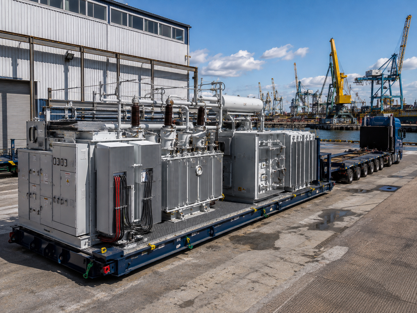
Inputs that make quotations comparable
| Quotation driver | What changes | What to send |
|---|---|---|
| Electrical duty | Active material, insulation, losses, impedance, temperature rise, and accessories | Single-line diagram, load schedule, utility data, and equipment datasheets |
| Port environment | Enclosure, coating, sealing, cooling, foundation interface, and maintenance provisions | Site conditions, corrosivity, flood elevation, wind and temperature criteria |
| Verification scope | Engineering hours, witness points, third-party services, test setup, and records | Applicable standards, inspection and test plan, acceptance criteria, and report format |
| Commercial scope | Packing, spares, supervision, destination logistics, and schedule risk | Quantity, destination, required delivery window, Incoterm request, and site-service scope |
Compare the initial investment with no-load and load losses, operating costs, utilization, utility tariff structure, maintenance access, spares, outage consequence, expected service profile, and future expansion. Add supply chain risk, freight, installation, and commissioning before using any payback figure.
- Talite receives the single-line diagram, load list, environmental duty, quantity, and schedule target.
- We identify missing interface, utility, protection, testing, and project-record inputs.
- We map the requirement to the appropriate transformer, substation, and switchgear platform.
- Technical clarifications, exclusions, drawings, acceptance criteria, and commercial scope are fixed in writing.
- Manufacturing and delivery schedules are issued against the approved technical baseline.
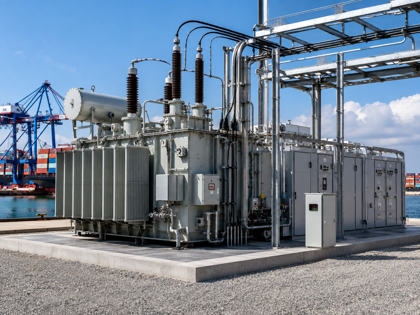
Quality Assurance and Project Documentation
We bring more than three decades of power-equipment experience to project review. Our documented manufacturing base includes 260 production and testing units, while the portfolio spans 22 series, more than 100 varieties, and more than 600 specifications.
IEEE C57.12.90 and IEC 60076 provide bounded transformer test and specification frameworks, but the applicable standard depends on transformer class and jurisdiction. A purchase specification must identify the edition, required tests, acceptance limits, exclusions, reporting format, and witness responsibilities.
Verification from specification to shipment
- Design review — confirm ratings, interfaces, standards, drawings, losses, impedance, temperature limits, accessories, and project hold points.
- Material and component control — align the bill of materials, purchased components, identification, and traceability with the approved design.
- In-process inspection — control core, winding, insulation, assembly, connections, enclosure, and documented process checkpoints.
- Test planning — define routine, type, special, witness, and third-party requirements by the named standard and edition.
- Release documentation — compile approved drawings, nameplate data, test reports, manuals, packing documents, and agreed certificates.

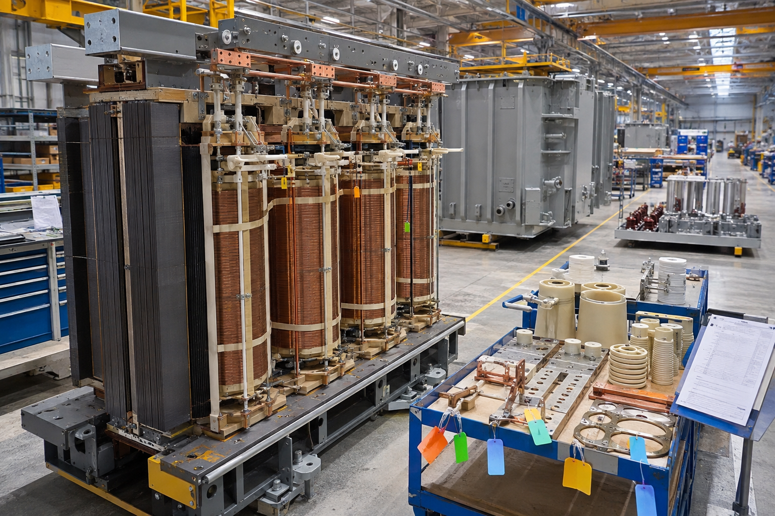
Documents to specify before award
- General arrangement and outline drawings
- Single-line and connection diagrams
- Guaranteed technical particulars
- Loss, impedance, and temperature-rise acceptance criteria
- Inspection and test plan
- Test report and witness-record format
- Operation and maintenance manual
- Packing, lifting, storage, and preservation instructions
“A useful port transformer review starts with the single-line diagram and load behavior, not with a catalogue rating. The drawing, test, and acceptance package then has to preserve those decisions through manufacture.”
Talite engineering review principle
How We Work: From Port Load Data to Equipment Delivery
Share the electrical baseline
— send the single-line diagram, load list, utility data, vessel-interface requirements, project location, and expansion plan.
Define duty and environment
— confirm load behavior, operating modes, redundancy, harmonics, corrosion, flood, structural hazards, temperature, and maintenance access.
Review configuration
— compare transformer type, capacity, voltage ratio, substation layout, switchgear, protection interfaces, monitoring, and serviceability.
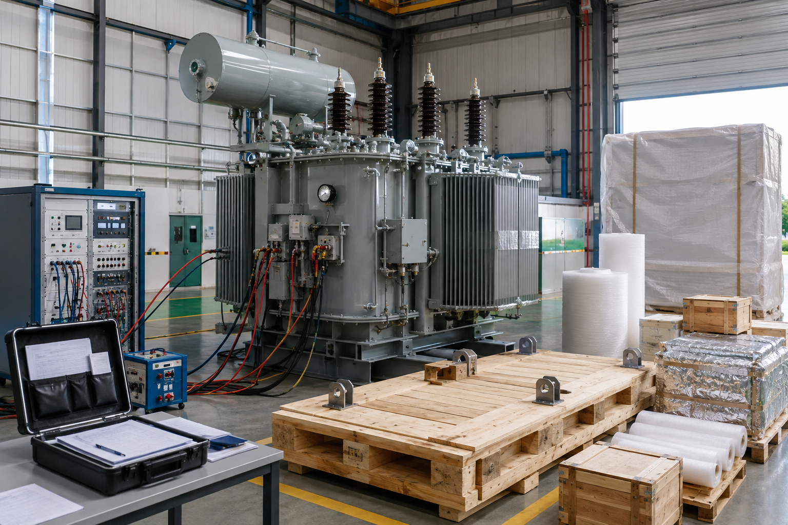
Freeze the technical package
— approve ratings, drawings, accessories, standard editions, acceptance criteria, documents, exclusions, and commercial scope.
Manufacture and verify
— build and test the equipment against the approved Talite supply boundary and recorded inspection plan.
Document and ship
— release the agreed reports, manuals, packing records, and equipment for the confirmed delivery scope.
Responsibility map
| Decision | Talite equipment scope | Project-team interface |
|---|---|---|
| Utility interconnection | Use approved system values in equipment design | Utility availability, upgrade, metering, tariff, and interconnection approval |
| Protection coordination | Supply equipment data and implement approved device requirements within scope | System study, settings philosophy, zone coordination, and authority approval |
| Shore-to-ship interface | Match approved transformer and substation requirements | Vessel compatibility, connectors, cable management, communication, and operating procedure |
| Civil and environmental design | Provide equipment loads, dimensions, clearances, and interface requirements | Foundation, elevation, drainage, fire, wind, seismic, access, and local permitting |
| Commissioning | Provide equipment procedures and agreed support scope | System integration, utility energization, vessel trial, safety validation, and operator training |
Engineering Trade-Offs and Alternatives
Good port electrification design does not force every load into one architecture. This selection matrix keeps system reliability, maintainability, space, fire strategy, expansion, and operating cost visible alongside the first equipment price; a berth electrification transformer is not interchangeable with a complete berth power system.
| Decision | Option A | Option B | Selection trigger |
|---|---|---|---|
| One large unit or multiple units | Centralized capacity and fewer primary assets | Redundancy, staged growth, and load segregation | Contingency criterion, berth availability, load diversity, space, and maintenance windows |
| Dry-type or liquid-filled | No insulating liquid in the transformer and a strong indoor/fire-safety fit | Broader high-capacity options and established outdoor substation practice | Capacity, location, fire and containment strategy, ventilation, efficiency, and maintenance |
| Central or distributed substations | Concentrated operation and maintenance | Shorter secondary feeders and closer alignment to berth or yard loads | Terminal geometry, cable cost, voltage drop, expansion stages, resilience, and flood strategy |
| Transformer only or frequency conversion | Fewer conversion stages when utility and vessel frequency match | Frequency compatibility across a defined vessel population | Utility frequency, vessel fleet, connection standard, losses, harmonics, controls, and redundancy |
| Standard enclosure or project-specific protection | Lower complexity for a controlled indoor environment | Tailored corrosion, flood, wind, heat, access, and monitoring provisions | Measured site hazards, jurisdictional loads, maintenance plan, and target asset life |
Marine Port Infrastructure Engineering Tools
Port Load Demand Worksheet
Calculate precise electrical load requirements for marine port terminals and shore power connections. Optimize power distribution sizing for maritime operations.
Transformer and Substation Configuration Comparison
Evaluate and select the most efficient transformer configurations for coastal applications. Systematically compare footprint, capacity, and environmental resilience.
Coastal Installation Input Review
Verify critical installation parameters specifically for harsh marine environments. Ensure strict compliance with anti-corrosion and heavy wind-load standards.
FAQ — Marine Port Infrastructure Transformers
Send the single-line diagram, primary and secondary voltage, connected and diversified loads, duty cycles, starting current, harmonics, frequency, redundancy criterion, future loads, environmental data, and utility fault information. The rated capacity is then checked against normal, peak, contingency, and expansion operating modes.
A port shore power transformer belongs to a shore-side electrical infrastructure system serving commercial vessels at berth. IEC/IEEE 80005-1 addresses high-voltage shore distribution, transformers or reactors, interface equipment, controls, monitoring, interlocking, and power management; recreational craft and onboard isolation products are outside this page’s scope.
Vessel demand, 6.6 kV or 11 kV receiving voltage where applicable, 50 Hz or 60 Hz frequency, connector and cable arrangement, earthing, fault behavior, communication, interlocks, power management, berth geometry, and call schedule all affect the plan. The port, vessel operator, utility, and system integrator must agree those interfaces before equipment design is frozen.
Large motors, ship-to-shore cranes, rubber-tired gantry cranes, pumps, variable-speed drives, frequency converters, battery chargers, and other power-electronic loads deserve separate data. Talite uses motor and converter information to review impedance, voltage regulation, thermal duty, power quality, and protection inputs.
Start with the serving utility’s available capacity, fault level, voltage and power-quality limits, then add the port’s phased shore power, reefer, crane, workshop, microgrid, and charging loads. The approved growth scenario should define reserved transformer capacity, feeder space, switchgear provisions, and the timing of upstream grid upgrades.
Provide atmospheric corrosivity, humidity, condensation, design flood elevation, storm surge, drainage, wind, seismic or tsunami criteria where applicable, ambient temperature, solar exposure, wildfire conditions, maintenance access, and target asset life. These inputs affect coating, enclosure, elevation, anchorage, cooling, cable entry, fire protection, spares, and recovery planning.
A central arrangement can simplify the operating location, while distributed units can shorten feeders, segregate loads, and support phased expansion. Compare voltage drop, cable routes, fault zones, berth availability, flood exposure, maintenance access, redundancy, and total lifecycle cost before choosing.
Provide the single-line diagram, load schedule, equipment datasheets, utility data, site layout, environmental criteria, required standards, inspection and test plan, documentation schedule, quantity, destination, and delivery target. If some values are not final, identify the design stage so assumptions can be written into the clarification list.
Routine, type, special, witness, and third-party requirements can be identified before award, but the exact list follows the transformer class and named standard edition. IEEE C57.12.90 and IEC 60076 provide test frameworks; the purchase specification should state acceptance limits, report format, witnesses, and exclusions.
Electrical rating, materials, losses, impedance, insulation, cooling, enclosure, accessories, monitoring, tests, documents, approvals, long-lead components, quantity, packing, and delivery scope all move the quotation. Send the project baseline and Talite will return a written technical and commercial scope instead of applying a generic product price.
Yes. We review the electrical, utility, shore-to-ship, environmental, testing, and documentation inputs that affect Talite’s transformer, substation, and switchgear supply boundary.