Get in touch with Talite Transformer Co., Ltd Company

![110kV Power Transformer Guide: Specs & Standards [2026]](https://toplit-transformer.com/wp-content/uploads/2026/07/110kv-power-transformer-guide-featured.png)
A 110kv power transformer is a substation-class piece of equipment that steps transmission-level voltage down to sub-transmission or distribution levels, most commonly to 10.5 kV, 11 kv, or 33 kV. It’s the equipment that sits between a bulk transmission line and the medium-voltage network that eventually reaches an industrial plant, a city grid, or a renewable-generation tie-in point – one of the core voltage-conversion nodes in any modern power system, carrying electricity onward from power plants toward the point of use.
Quick Specs
| Primary voltage | 110 kV |
| Common secondary voltages | 10.5 kV, 11 kV, 33 kV |
| Power rating range | 5-100 MVA (Talite production range); industry-wide up to 400 MVA |
| Cooling classes | ONAN / ONAF / ODAF, three-phase, oil-immersed |
| Voltage regulation | On-load tap changer (OLTC), commonly ±8×1.25% or ±2×2.5% |
| Governing standards | IEC 60076 series, IEEE C57.12.00 |
A 110kv power transformer steps transmission voltage (110 kv) down to sub-transmission or distribution levels – commonly 10.5, 11, or 33 kV – at a substation. It usually operates in the 5-100+ MVA range, uses oil-immersed ONAN/ONAF/ODAF cooling, and is built to IEC 60076 and IEEE C57.12 standards.
Key Points
- None of the current top-ranking pages for this term cite a single government or IEEE standard directly by link – this guide does.
- Right now, the real constraint on 110kv transformer delivery isn’t factory floor space – it’s a single domestic supplier of the core steel and a built-to-order manufacturing model.
- “power transformer” and “distribution transformer” aren’t split by a fixed voltage number – the boundary is functional, not numerical.
- Average lead time for a standard power transformer has reached roughly 128 weeks – procurement conversations need to start well before final design freeze.
- Working engineers still disagree on whether the OLTC belongs on the high-voltage or low-voltage side of a 110kv-class unit.
What Is a 110kV Power Transformer?
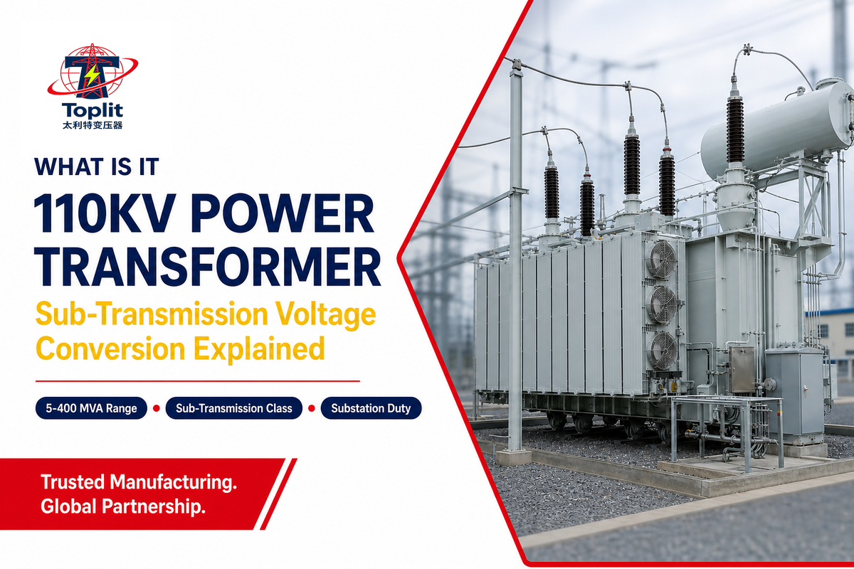
A 110kv power transformer is one of the units doing sub-transmission voltage-conversion work: it takes the 110 kv that arrives from a transmission line and converts it to whatever the downstream network actually needs – 10.5 kV, 11 kv, or 33 kV in most global markets, though secondary voltage is customized per project.
According to the U.S. Department of Energy, more than 90% of the power consumed in the United States passes through a high-voltage transformer at some point between the generating plant and the end user (DOE Office of Electricity).
Ratings vary widely by application. Industry-wide, 110kv-class units are built anywhere from roughly 5 MVA up to 400 MVA for the largest grid-backbone installations – a 270 MVA transformer would sit toward the upper end of that range – though most projects fall well short of that ceiling.
Talite’s own production range for this voltage class runs 5 to 100 MVA across 22 series, 100+ varieties, and 600+ specifications, built and shipped to 30+ countries – a representative unit in that range, for example a 20 mva oil-immersed power transformer, would usually carry a secondary voltage of 11 kv or 13.8 kV and a three-phase, ONAN/ONAF cooled design. One common buyer mistake at this stage is treating “MVA rating” and “physical size” as interchangeable when requesting quotes; because cooling class and insulation level both drive footprint independently of MVA, two 20 MVA units from different manufacturers can differ meaningfully in tank size and weight. When comparing a 110 kv power transformer against a 110kv 115kv power transformer listing (110kv and 115kv power ratings are effectively the same equipment class, just labeled to different regional grid conventions, and some catalogs even group them as “110kv 115kv” in one line item) – the technical specifications that actually matter are MVA power transformer rating, cooling code, and BIL, not the nameplate voltage label alone. The equipment moves electrical power at scale, one of the load-bearing nodes of any regional power grid.
About This Guide
Talite has designed 110kv-220kV oil-immersed and dry-type power transformers to IEC 60076 and GB/T standards for more than 30 years from its Hai’an, Jiangsu factory. This guide draws on that manufacturing background alongside government, standards-body, and trade-press sourcing so a reader evaluating 110kv equipment gets the same technical grounding our own engineers work from – not just a sales sheet. Reviewed by the Talite technical team.
Core, Windings, and Insulation: How a 110kV Transformer Is Built
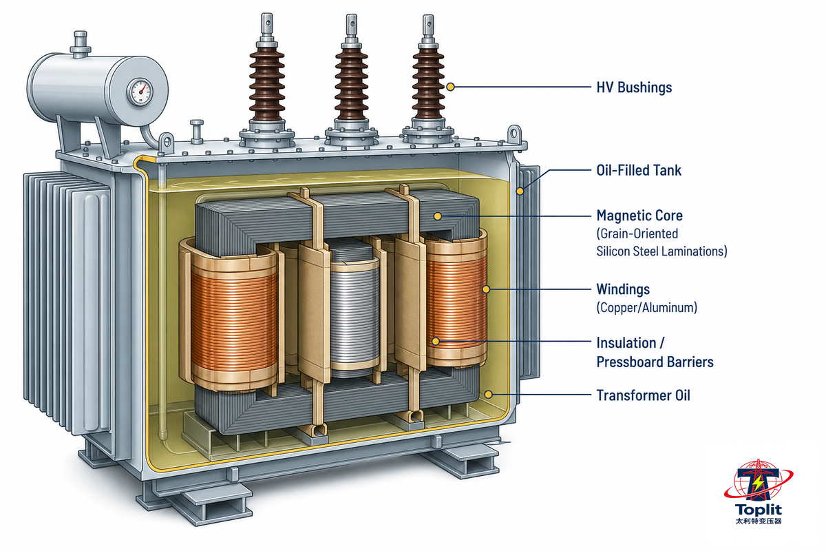
“Remove the tank and you’ve a transformer consisting of three essential elements working in unison: a magnetic core, a coil set, and an insulation framework capable of withstanding both continuous operating voltages and momentary surges from lightning.” The magnetic core is constructed out of layers of grain-oriented silicon steel sheet. Latest patent filings, such as one published with the United States Patent application number US7692523B2, describe the use of a single regulating winding paired directly with a tap changer without the need for a secondary auto transformer in a more streamlined construction.
Chinese filed patents relating to the pin configurations of 110kV and above wound cores suggest continuing industry wide effort toward optimized core configurations. Windings – the coils that generate magnetic fields to interact with the core – consist of one, two or three distinct groups or layers each constructed of copper or aluminum wire or bar. These coils are wound around the magnetic cores, then insulated using press board and paper, to ensure a high level of dielectric strength and stable insulation across the unit’s full operating temperature swing. Inspecting the windings of the transformer during a factory acceptance test is one of the most direct ways to verify a 110 kv transformer was actually built to the spec sheet rather than just labeled to it.
📐 Engineering Note
“It’s commonplace for such transformer classes, as the 110kv, to operate at a Base Insulation Level of 550 kV on the HV side; this represents the standard-wide specification for the insulation’s ability to handle high-voltage lightning-impulse surges, independent of the continuous load voltage,” the guide states. “For reference purposes, this is double checked by comparing two independent competitor spec sheets rather than relying upon one source; consult your local, provincial, or state standards body for specific levels of 110kV transformer equipment that may be specified.”
🔎 The 110kV Transformer Spec Decoder
“A nameplate spec sheet is a concise summary of a transformer; below is the more practical, line by line breakdown of the information most people scan past…”
| Nameplate field | What it tells you |
|---|---|
| Vector group (e.g., YNd11) | Winding connection type and phase-shift angle — must match on both sides of a parallel-operation pair |
| BIL (kV) | Lightning-impulse withstand rating of the insulation, not the operating voltage |
| Impedance voltage (%) | Limits fault current and sets parallel-operation compatibility with other units |
| No-load loss / load loss (kW) | Core loss (constant) vs winding loss (varies with load) — drives lifecycle energy cost |
| Tap range (e.g., ±8×1.25%) | How far the OLTC can move secondary voltage without changing the physical winding |
| Cooling code (ONAN/ONAF/ODAF) | Which heat-removal method is active at which load stage — see the cooling section below |
Physical scale is important to the overall transport and foundation planning as well, for the purpose of comparison the 20 mva in a typical 115kV-class would be about 5m high, 3.8m deep by 6m wide for an overall shipping weight of about 35,000 kg, of which some 8,140kg would be transformer oil, scale those figures up for the larger models with 50-100MVA ratings and one can see the large amount of logistical planning that comes into play long before any of these arrives at site and impacts upon the design of your transport vehicle or reinforced foundations.
Bushing failure on a 110-kV unit is one of the more serious possible failures of this insulation system in the field, and a well-known documented incident from T&D World shows what that actually looks like: one 110-kV oil-impregnated-paper (OIP) bushing on an 80-MVA transformer failed, and the fire that resulted from it spread through the unit so rapidly that it was contained only because the transformer itself and the enclosure for its sound and noise reduction happened to contain the flames rather than allowing them to reach the other connected equipment (T&D World). This is an instructive example of why the simple quantitative framing of “risk equals probability times consequence” matters for insulation-system decisions in particular: bushings don’t usually fail in service, but the failure of just one to take down an 80-MVA transformer with a fire is an absolute worst-case consequence, and that element of the risk equation would still be there were the failure to occur at a jumper that’s maybe a third of the size, in a much smaller unit. Bushing, the Buchholz relay, and the pressure-relief valve are in place to prevent that kind of degradation from reaching the point where it would do that kind of damage. These transformer protection devices, together with the temperature of the transformer being monitored continuously, are how a well-designed transformer core and tank assembly catches insulation problems before they become failures – a buyer evaluating parts of the transformer on a factory acceptance report should confirm each of these protection elements is present and functioning, not just the transformer body and transformer tank dimensions.
Where 110kV Sits in the Voltage Hierarchy
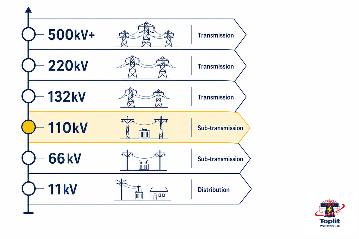
110kv sits in the sub-transmission tier, one class below 132/138kV and two below 220kV, and the “power transformer” vs “distribution transformer” boundary is functional rather than a fixed voltage number. Two questions come up over and over: how is a “power transformer” different from a “distribution transformer,” and how do you know 110kv – not 66kV, 132kV, or 220kV – is the right voltage level for a project?
Power Transformer vs. Distribution Transformer
There isn’t a fixed, industry-standard cutoff within voltage that divides the two classes for engineering purposes, and using a simple number in specifications is one of the more common specification errors that customers make – industry problem-analysis reports identify “picking the wrong voltage class for your power source” as one of the recurring real-world disconnects behind transformer problems (GigaEnergy). In practice, the distinction engineers use is functional: a power transformer moves bulk power at transmission or sub-transmission voltage between grid nodes – generation to transmission, transmission to sub-transmission, sub-transmission into a substation. A distribution transformer takes that already-stepped-down power and delivers it to the final consumer, usually as a smaller pole-mounted transformer or pad mounted transformer unit. Stepping a 110kv unit down to 33kV at a substation is still doing power-transformer work, even though 33kV itself sounds “distribution-scale” to someone outside the industry. Distribution transformers themselves typically step down through a secondary range as low as 7.2-34.5 kv on the primary side before final power distribution to homes and businesses across both urban and rural power grids, which is a different job entirely from the sub-transmission role a 110kv unit performs. Neither term should be confused with a small single-phase transformer or an isolation transformer used for equipment-level galvanic separation in electronics – those operate at a completely different scale and purpose than the grid-connected units this guide covers.
One particular exception: U.S. regulations for energy efficiency explicitly define a line between the two; under 10 CFR § 431.192, the U.S. Department of Energy says that a distribution transformer is one with an input line voltage of 34.5kV or less and an output line voltage of 600V or less, and offers additional factors for capacity and other exclusions. A 110kv unit steps down from a substation to 33kV, but on the input side alone this places it well outside the DOE definition, so in the case where a specification needs to comply with U.S. energy-efficiency standards specifically, the boundary still is a hard number, even though for general engineering usage the terms still don’t have a fixed number between them.
110kV vs 132kV vs 220kV
Adjacent voltage classes exist because grid topology, not equipment preference, drives the choice. 110kV and 132/138kV are both common sub-transmission tiers depending on regional grid standards (110kV is dominant in China, much of Europe, and parts of Asia; 132/138kV is more common in parts of the Commonwealth and North America). A 138kV transformer serves the same functional role as a 110kV unit, just one class up, and the two are chosen based on regional grid standards rather than project size. 220kV sits a full tier higher, used for longer transmission runs and higher-capacity bulk transfer, see our 220kV power transformer guide for that class’s specific loss-capitalization and rating data, which we won’t duplicate here. Below 110 kV, the same logic holds in reverse: 66 kV and 72.5 kV units handle shorter sub-transmission runs or smaller industrial feeds, while 20 kV sits closer to the distribution primary tier – a 132 kV transformer is simply the next class up from a 110kv unit, not a different technology.
| Voltage class | Typical role | Where it’s dominant |
|---|---|---|
| 11-13.8 kV | Final-mile distribution secondary | Global, near-universal end-use tier |
| 33-35 kV | Distribution primary / light sub-transmission | Global regional distribution |
| 66-69 kV | Sub-transmission, shorter runs | Regional/legacy grids |
| 110 kV (this guide) | Sub-transmission to substation step-down | China, much of Europe/Asia |
| 115 kV | Sub-transmission, near-equivalent to 110kV class | North America |
| 132-138 kV | Sub-transmission to substation step-down | Parts of Commonwealth, North America |
| 220-230 kV | Bulk transmission, longer runs | National grid backbones |
| 330-400 kV | High-capacity bulk transmission | Large national grids (e.g., Fingrid’s Finnish backbone) |
| 500 kV+ | Ultra-high-voltage long-distance transmission | Continental-scale grid interconnection |
🪝 The 4-Signal Voltage Class Ladder
Prior to getting quotes, compare the following four signals with your project – if three or more of them indicate the same thing, you’ve your class:
- Existing infrastructure: What voltage does the adjacent substation or incoming transmission line already run at? class mismatch requires an additional transformation stage
- Transmission distance: long distance from transmission generation would benefit the next size class up (220kv vs 110kv) as to try and maintain losses on the line down.
- connected capacity (MVA): for large loads, greater than 100MVA, the choice is increasingly towards infrastructure in 220kV-class rather than the assembly of multiples 110kv:
- Local grid code the sub-transmission for you may be fixed on the basis of national and regional grid codes (GB, IEC, or regions ANSI) regardless of the particular project you under take.
Where 110kV Power Transformers Are Used
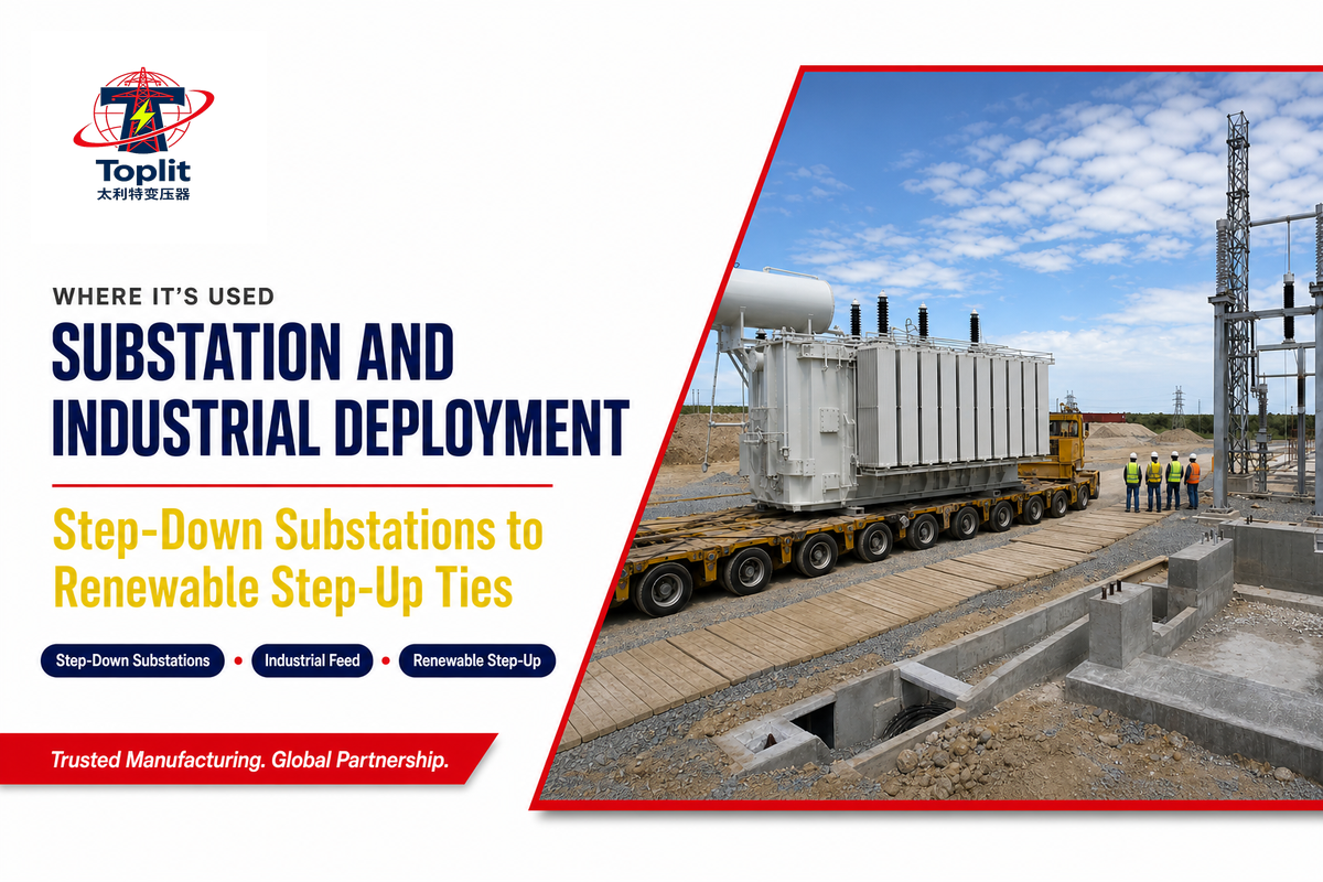
110kV power transformers are used most commonly in step-down substations, large industrial-feed connections, and renewable step-up applications. In the step-down substation case, a 110kV line comes in from the transmission network and the transformer brings it down to a level the local distribution grid or a large industrial consumer can use directly.
New Zealand’s Masterton Substation is a straightforward, real-world example of exactly this role. When its aging units reached end-of-life, the local network operator replaced them with two new transformers that “convert the 110-kV Transpower grid supply to 33 kV” before it ever reaches a home or business meter, according to T&D World‘s coverage of the project (T&D World) — the replacement kept a regional town’s entire electricity supply dependent on that single 110/33kV conversion point working reliably. At national-grid scale, the same pattern repeats: Finland’s transmission operator Fingrid runs roughly 8,700 miles of transmission line and 113 substations spanning 110kV to 400kV, with 110kV forming the lower end of a multi-tier backbone that serves the entire country.
Above these substation utility equipment is also found anywhere large industrial sites pull a transmission class service rather than buying smaller voltage power. These include large manufacturing facilities, petrochemical sites, and recently even at renewable generation facilities, where they push their produced power through a “step up” transformer and inject their power matching the high voltage of the local network’s grid. Talite’s own 110-220kV oil-immersed units, certified to ISO 9001, ISO 14001, and ISO 45001 and built at its Hai’an, Jiangsu facility, are engineered for exactly this substation and industrial-feed role – a risk many buyers overlook is specifying a unit for the wrong application class, because a substation-duty transformer and an industrial-feed unit can carry different loading-cycle and overload assumptions even when their MVA rating is identical. Buyers sourcing a high voltage oil immersed power transformer directly from the plant – what some listings shorthand as buying transformer factory direct – should still confirm ISO-certified production and full test documentation are in place before signing, since a factory-direct claim on its own isn’t verification.
Cooling Classes Explained: ONAN, ONAF, and ODAF
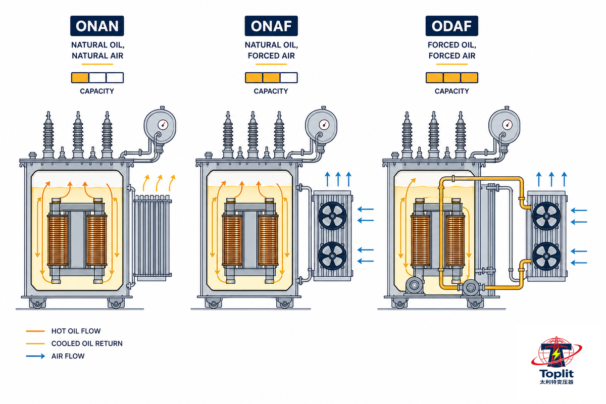
Those two letters after a transformer’s MVA rating (Oil Natural, Air Forced in this case) represent cooling code designations defined in the same IEEE C57.12.00 standard that governs liquid-immersed power transformer design generally, and are important because they dictate the carrying capacity of a physical unit in a particular unit of time. ONAN (Oil Natural, Air Natural), as you can see, doesn’t use any active components whatsoever. Heat from the core drives a natural circulation of transformer oil, which dissipates itself to the atmosphere via the tank and radiator surface.
ONAF (Oil Natural, Air Forced) adds fans in front of the radiator that increase the thermal transfer and boost capacity. The step beyond that, ODAF (Oil Directed, Air Forced), adds oil pumps in order to direct the circulation of cooling oil when under load through the windings themselves.
In practice, this means staged capacity from a single physical transformer. One vendor’s standard published 115kV unit, for example, is rated for 12 MVA using only ONAN cooling, and 16 MVA with a single level of fan cooling engaged (ONAF1). With a second level of fans enabled (ONAF2), it reaches 20 MVA – calculated from those same published figures, roughly a 65% capacity boost from a single core and windings, just by adding active cooling.
That logic drives multiple stages of cooling: put a core that can handle the load, and then don’t worry about running it hot under normal operating conditions.
✔ Oil-Immersed (ONAN/ONAF/ODAF) Advantages
- Mineral oil serves for both cooling and dielectric medium-no additional insulation required
- Staged cooling (ONAN/ONAF/ODAF) allows a single core to serve a wide capacity range
- Mature, accepted practices (Oil sampling, Buchholz relay, DGA testing)
⚠ Oil-Immersed Limitations
- Fire and environmental risk from mineral oil in dense urban or indoor installations
- Needs a conservator tank, oil level and pressure monitor, and regular testing of the oil
- Heavier & more transport restrictive than comparable dry rating
In cases where the fire and environmental profile of oil is problematic – densely populated urban substations, indoor installations – the industry has been moving toward more biodegradable natural ester fluids, offered for instance under brand names such as FR3, as a drop-in replacement for mineral oil that has a higher flash point and biodegrades more quickly, all while maintaining the same ONAN/ONAF cooling setup. This hasn’t reached “default choice” status yet at the 110kv scale, but whether natural-ester alternatives suit your site conditions at a project level is certainly worth posing to any supplier.
Voltage Regulation: How the On-Load Tap Changer (OLTC) Works
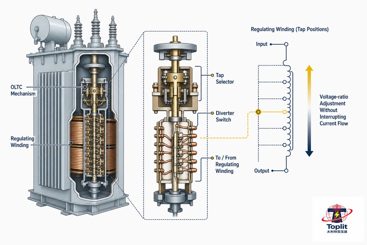
Grid voltage is a fickle thing, constantly sloshing about the network with load conditions, time of day, and activity elsewhere on the system. A 110kv transformer has got to smooth out the fluctuations without shutting the system down, and that’s where the on-load tap changer comes in. An OLTC operates by physically moving the contact on the regulating winding, thereby changing the effective turns ratio, and thus the secondary voltage, without the interruption of current flow. U.S. patent US7692523B2 spells this out: “transformer comprised of … a regulating winding and … a tap changer that selects a tap position along the regulating winding …” in order to control output voltage. A typical range for an 110kV-class transformer might be around ±8×1.25% or ±2×2.5% of rated voltage in a set number of steps, not continuous control. The technology itself isn’t new; on-load tap changing became common on 110kV and higher transformers well over two decades ago, progressing from reactor-based systems to today’s most prevalent resistor-based OLTCs.
📐 Engineering Note
A typical 110kv OLTC has 8 taps at 1.25% (approximately 10% range) or 2 taps at 2.5% (approximately 5%). Finer taps in the 1.25% configuration provide more exact voltage control but will lead to more mechanical switching operations over the course of the unit’s service life. Provenance note: cross-verified via two manufacturer spec sheets and confirmed with industry experts to be standard practice for the 110kv product line, not a sole-source claim, but verify the total range against your specific project’s electrical study prior to procurement. Maintaining transformer condition and the overall performance of the transformer over a multi-decade service life depends heavily on this mechanism: a maintenance program that doesn’t track OLTC operating counts and contact wear can’t ensure that the transformer keeps regulating voltage correctly, so most FAT and commissioning checklists treat OLTC operation of the transformer as a distinct item affecting the overall reliability of the transformer, separate from the core and windings and evaluated on its own switching-cycle count rather than assumed to last as long as the passive parts.
Can a 110kV Transformer Step Directly Down to 69kV?
No, not in a single standard unit designed for the 110kV/33kV or 110kV/11kV range: 69kV falls into a different sub-transmission tier that typically requires either a dedicated 110/69kV unit specified for that exact ratio, or an intermediate step through a separate transformation stage.
These two voltage classes are close enough that they’re sometimes discussed interchangeably in casual conversation, but the winding ratio, tap range, and insulation coordination all have to be engineered for the specific combination, a 110/33kV unit can’t simply be re-tapped to deliver 69kV output. If a project genuinely needs both a 110kV feed and a 69kV distribution tie, that’s a case to raise directly with your transformer manufacturer during the specification stage rather than assuming standard catalog units will flex to fit.
On a less settled industry front, there’s one question of placement: should the OLTC go on the high-voltage or low-voltage side of the winding? That has sparked lively debate among working engineers at the eng-tips.com forum, with at least one camp arguing that placement on the HV side leaves the tap changer exposed to an estimated 10-15% of line voltage with one end “solidly grounded,” thus minimizing insulation stress on the switching mechanism. Another counter: “utility and industrial users have extensive experience on the LTC performance on the LV side.” In the field, the decision is almost always based on specific manufacturer standards and on the project’s fault-current and insulation co-ordination study. Dismiss any claims that one approach is definitively correct out of hand.
Standards and Testing: What IEC 60076 and IEEE C57 Actually Cover
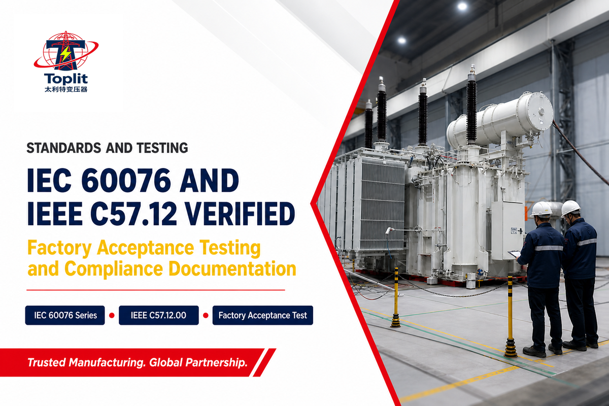
Almost all 110kv power transformers for global use fall into one of two main families of standards. The IEC 60076 series is the premier international power transformer standard (International Electrotechnical Commission), broken out into its sub-components: general requirements (IEC 60076-1), insulation levels and dielectric testing (IEC 60076-3), and specific requirements for testing of dry-type transformers (IEC 60076-11). The equivalent American standards document is ANSI C57.12.00 (now IEEE C57.12.00), currently in its 2021 version, applying to “all liquid-immersed distribution, power, and regulating transformers,” with a short list of specific exclusions such as instrument transformers (IEEE Standards Association).
In order to make sense of such standards, buyers need to be able to differentiate between the ‘design’ criteria – how the transformer will be engineered-and’test’ requirements – how the finished unit is validated prior to shipment. Standard testing sequence for a 110kv unit, for instance, includes measuring winding resistance and voltage ratio; confirming vector group and phase displacement; measuring no-load and load losses at various voltage points; exercising the on-load tap changer through its full range; and performing a lightning-impulse withstand and induced-voltage test with partial-discharge measuring. The corresponding test-scope tables in the chosen standard set out which tests run on a representative unit (short-circuit withstand, full temperature rise) rather than every production machine. This is also where transformer testing and the underlying transformer specifications diverge from marketing claims: a datasheet states the load a transformer is designed to carry, but only the routine and type-test reports prove the physical unit shipped actually meets that design. Buyers who don’t personally inspect the transformer test reports against the nameplate specifications are trusting the supplier’s word rather than verified evidence.
Such as Talite, whose 110-220kV oil-immersed and dry-type transformers comply with IEC 60076 series and GB/T 6451/GB/T 10228, and bears ISO 9001, ISO 14001, ISO 45001, and CCC certifications throughout its facility. Knowing what’s supposed to be contained in a standard is one thing; verifying that a particular supplier’s factory acceptance test (FAT) documentation demonstrates their particular production units conform, is another more in-depth matter – our 110kv transformer RFQ and FAT evaluation guide covers this process thoroughly with a readiness checklist of questions to ask prior to soliciting quotes. And with current industry surveys showing an average lead time around 128 weeks for standard power transformers, your process for document verification and supplier qualifications need to begin even sooner – see “Industry Outlook” section below to get a jumpstart.
Industry Outlook: What’s Changing in the 110kV Transformer Market
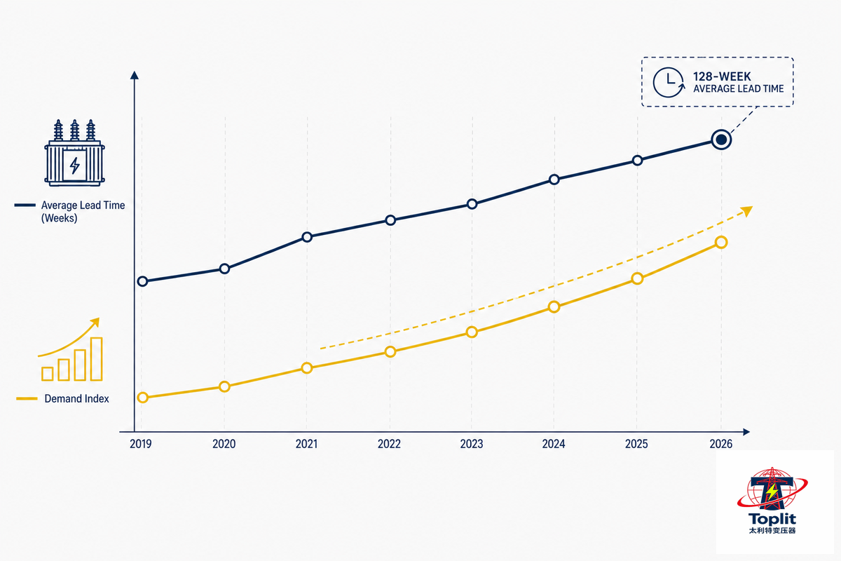
The binding constraint at this moment on procuring new 110kvs isn’t the demand growth – rather, it’s a supply chain with lead times approaching 128 weeks (close to two and a half years) for standard power transformers, according to Wood Mackenzie’s own Q2-2025 supply-chain survey in collaboration with American Clean Power, with lead times for some very large, customized units stretching out much further- compared to a North American grid on which the U.S. Department of Energy indicates the average large power transformer is about 38-40 years old (a number DOE itself sources to its 2012 and 2014 fleet studies, and reaffirmed (but not remeasured on any new set of unit-level data) in DOE’s 2024 report on large-power transformer resilience to Congress. This number isn’t Wood Mackenzie’s; it’s the DOE’s cited figure, sourced back to 2014-not independently collected today-and industry analysts are concerned it’s frequently used in applications beyond DOE’s initial scope focused solely on the large-power transformer supply chain. To know if a buyer begins procurement after a project is already underway, it’s important to know a buyer is selecting a multi-year waiting list out of hand. According to the same Wood Mackenzie survey, demand for generator step-up transformers has swelled by 274 percent since 2019 and standard power transformer demand has jumped by 119 percent, driven not by any single item, but a confluence of three trends- AI-driven data center expansion, the electrification of industries, and the necessity of replacing outdated, aging grid equipment, each placing strain on the same limited pool of manufacturing capabilities and expertise.
Just how much a single transformer can matter became clear in March 2025, when a fire occurred at the North Hyde substation site, adjacent to London’s Heathrow Airport, and disabled the transformer responsible for providing power to one of the world’s busiest transit hubs. According to Bloomberg News’ reporting on the incident, the incident prompted 1,000 flight cancellations while emergency responders worked over seven hours to contain an estimated 25,000 liters of flaming transformer cooling fluid. Replacing this single unit is by no means an overnight job; grid-technology specialists quoted in the same Bloomberg coverage estimate that obtaining a comparable replacement would require more than one year even excluding today’s transformer crunch. These are the sorts of ramifications for which timely procurement-not the price alone-is the principal determinant for a new 110kv project. Treating transformer price as the sole procurement variable, while ignoring lead time and real-world transformer performance under load, is exactly the mistake the current supply crunch is punishing across 110kv and 132kv transformers alike.
The intrinsic structure of the problem that inhibits the industry from building new factories at scale, while worth examining in its own right since it explains why investment of more than two billion dollars across new North American factories since early 2023 hasn’t yet relieved the shortage, is that such transformers are custom orders rather than products of assembly-line manufacturing. “It’s not mass manufacturing,” Eduardo Villar, a production specialist for GE Vernova, explained in the Bloomberg article. ” We’re not making bottles.” Every transformer contains numerous custom components, and the primary construction material – grain-oriented electrical steel, or GOES – comes from a singular domestic supplier in the United States (Cleveland-Cliffs, based in Ohio and Pennsylvania); in fact, roughly eighty percent of large power transformers employed in the U.S. must be imported. Because one such bottleneck is present in the global supply chain, that constrains the entire U.S. industry, no matter how many assembly operations are added domestically.
“The technology used to build modern transformers is already more than 100 years old. It’s not rocket science.”
That maturity cuts both ways: it means the core engineering is well understood and reliable, but it also means there’s no fast technological shortcut waiting in the wings. Solid-state transformers – which could shrink the physical footprint and add grid-communication capability standard units lack – remain years from commercial availability at this scale. Global power transformer market value is projected in the high-$20-billion range for 2026 with continued growth through the early 2030s per multiple market-research estimates, but that figure is directional background, not the reason to act – the lead-time and asset-age data above is.
The picture isn’t uniformly worsening, either – Wood Mackenzie’s own supply-chain analysts project generator step-up transformer shortages narrowing from over 700 units in 2025 to roughly 140 units by 2030 as expanded production capacity and moderating renewable-generation growth start to ease pressure specifically on that sub-category, even as the broader 110kv-class power transformer picture remains constrained through the near term.
Not everyone frames this purely as a capacity shortage, either. Some industry voices argue the constraint has as much to do with procurement practices – how far in advance utilities and developers lock in orders – as with raw manufacturing capacity, since transformer, switchgear and cable shortages are all running in parallel across the broader transmission-and-distribution equipment category rather than being isolated to one component. If you’re planning a 110kv project for 2026 or beyond, the practical takeaway either way is the same: start specification and supplier-qualification conversations at the feasibility stage, not after design freeze.
Frequently Asked Questions
Q: What does “110kV” mean for a substation transformer?
View Answer
“110kv” refers to the rated primary (high-voltage) side of the transformer – 110,000 volts. It describes the voltage the unit receives from the incoming transmission or sub-transmission line, not the voltage it outputs. The secondary side, which feeds the downstream network, is usually stepped down to 10.5 kV, 11 kv, or 33 kV depending on the project.
Q: Is it dangerous to be near a 110kV transformer, and what’s the safe clearance distance?
View Answer
Yes – 110kv equipment operates at a voltage that can arc across significant air gaps, and substations housing it are fenced, signed, and access-restricted for exactly that reason. Minimum approach and clearance distances are set by the applicable electrical safety code for your jurisdiction (such as national electrical safety codes or IEC clearance tables) and depend on the specific insulation coordination of the installation, not a single universal number. Anyone working near live 110kV equipment should follow their utility’s or employer’s documented safe-approach-distance procedure rather than a generic figure found online.
Q: Which standards govern 110kV power transformer design and testing?
View Answer
The IEC 60076 series (international) and IEEE C57.12.00 (American, currently the 2021 edition) are the two primary standards families governing 110kv power transformers, covering general design requirements, insulation levels and dielectric tests, and both routine and type testing procedures. Many manufacturers building for multiple export markets also design against national standards in parallel, such as China’s GB/T 6451 or GB/T 10228, layered on top of these two international baselines rather than replacing them.
Q: How is 110kV transformer oil tested and maintained?
View Answer
In addition, its routine maintenance comprises dissolved gas analysis to diagnose incipient insulation breakdown, dielectric strength and moisture testing, and regular monitoring of the Buchholz relay, oil level, and pressure-relief mechanisms. Replacement or re-oiling is typically dictated by the test results rather than by a strict calendar schedule.
Q: What’s a realistic lead time for a new 110kV oil-immersed transformer?
View Answer
According to recent industry survey data (Wood Mackenzie, Q2 2025), common power transformer variants currently carry order-to-delivery lead times of roughly 128 weeks – almost two-and-a-half years – and special orders may take longer. That timeframe represents a generic market outlook across the power transformer spectrum, not a quote from a specific manufacturer. But factors such as a given transformer manufacturer’s current order queue, particular product customization and material availability at the time of placing an order have a significant bearing on the actual lead time. Taking this and lead times into account, a supplier selection and specification discussion should begin well ahead of a project’s final investment decision.
Q: Can a 110kV transformer be used on a 66kV or 69kV system instead?
View Answer
Not as a standard, off-the-shelf substitution. A 69kV transformer, a 66kV unit, and a 110kV transformer are distinct sub-transmission voltage classes with different winding ratios, tap ranges, and insulation coordination requirements. A transformer engineered for 110kV primary input cannot simply be re-tapped to accept a 66kV or 69kV feed reliably — a project genuinely spanning both voltage classes needs a unit specified for that exact combination from the outset.
References & Sources
- Addressing Security and Reliability Concerns of Large Power Transformers: U.S. Department of Energy, Office of Electricity
- Large Power Transformer Resilience Report to Congress: U.S. Department of Energy (2024)
- IEEE C57.12.00-2021: IEEE Standards Association
- 10 CFR § 431.192, Definitions: Electronic Code of Federal Regulations, U.S. Department of Energy
- The One Device Throttling the World’s Electrified Future: Bloomberg
- Supply Shortages and an Inflexible Market Give Rise to High Power Transformer Lead Times: Wood Mackenzie
- Mind the Gap: Tackling Supply-Chain Challenges in the Electric T&D Sector: Wood Mackenzie
- Power Transformer Lead Times Hit Record Highs as U.S. Grid Equipment Shortage Deepens: IndustrialSage
- Masterton Substation Celebrates Two New Replacement Transformers: T&D World
- Risk Equals Probability Times Consequences: T&D World
💡 Talk to Talite About a 110kV Project
Talite is a supplier and manufacturer of 110 to 220 kV oil-immersed and dry-type power transformers compliant with the latest IEC 60076, GB/T 6451 and GB/T 10228 standards, operating from its facility in Hai’an, Jiangsu. Please contact us directly for direct answers regarding the capacity of a 110kv model, as well as its cooling class and availability ahead of the official RFQ process.
Related Articles
- 110kV Power Transformer: RFQ Readiness and FAT Evaluation Guide: evaluating supplier quotes and test documentation once you’re ready to buy
- 220kV Power Transformer Guide: guaranteed-loss data and ratings for the next voltage tier up
- Power Transformer Manufacturer: Supplier Qualification Guide: how to evaluate and shortlist a power transformer supplier
- Talite Transformer, Home
![Pad-Mounted Transformer: How It Works [2026 Guide]](https://toplit-transformer.com/wp-content/uploads/2026/08/pad-mounted-transformer-guide-featured-150x150.png)
![Single Phase Pad Mounted Transformer Guide [2026]](https://toplit-transformer.com/wp-content/uploads/2026/08/single-phase-pad-mounted-transformer-guide-featured-1-150x150.png)