Get in touch with Toplit Transformer Co., Ltd Company

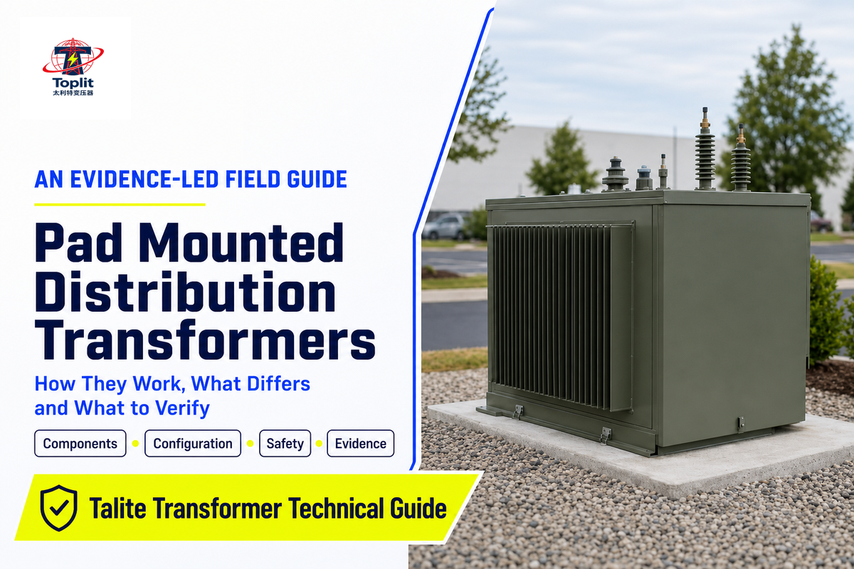
Technical field guide
Pad mounted distribution transformers are familiar pieces of utility equipment, yet their labels, interfaces, evidence and site responsibilities are often mixed together. This guide explains the equipment as a system so you can ask better questions without treating a general article as an installation manual.
IdentifyWhat the term includes and where its boundaries sit.
CompareWhich configuration choices are independent.
VerifyWhat a rule, standard or report actually proves.
Hand offWhich decisions belong to utilities and qualified parties.
Scope note: this is an informational guide for planners, engineers, facility teams and technical buyers. Medium-voltage equipment can cause fatal injury. Access, operation, testing, installation, maintenance and energization belong to the serving utility and qualified people working under the governing rules and procedures.
What Is a Pad-Mounted Distribution Transformer?
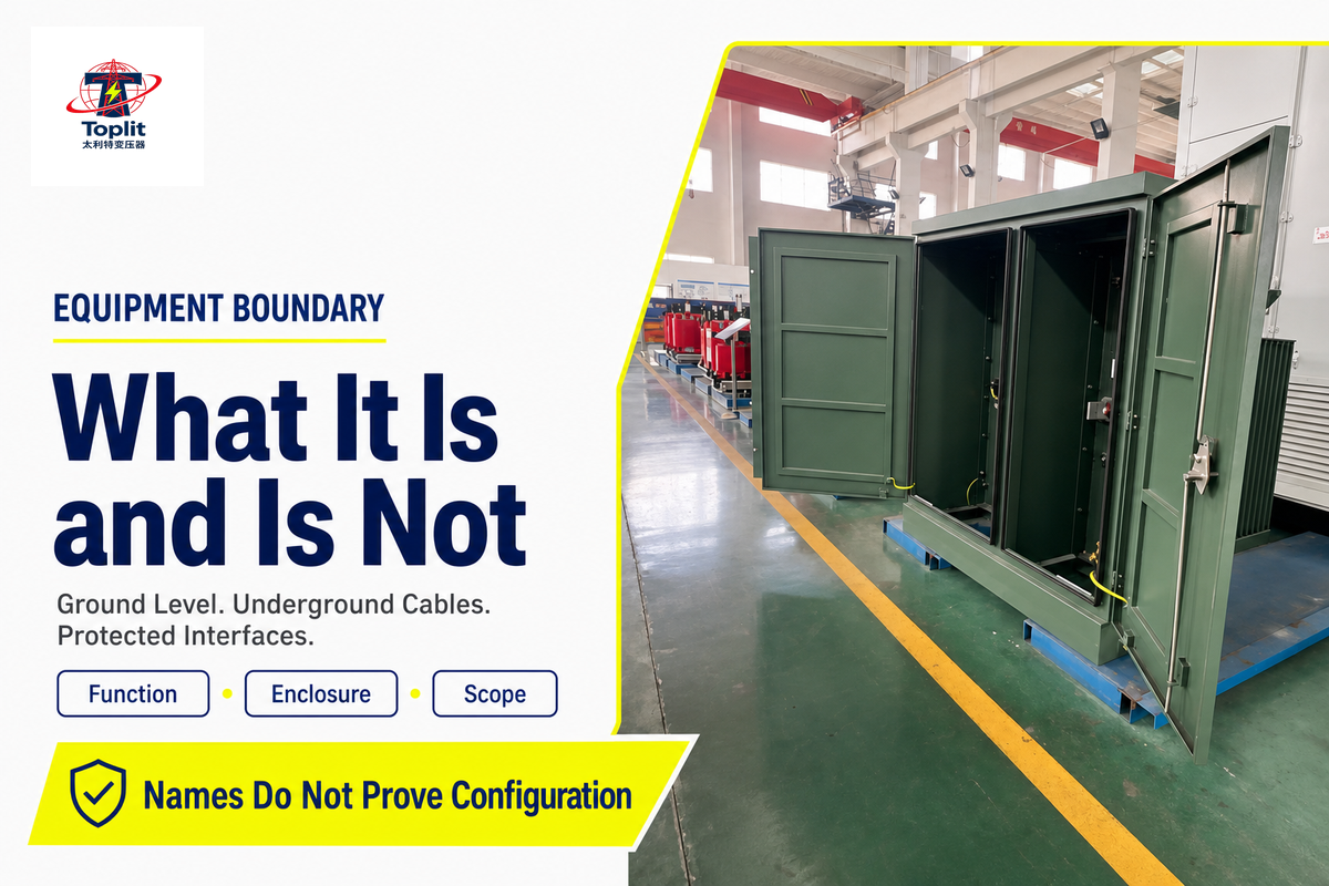
A pad-mounted distribution transformer is a ground-level transformer assembly intended to receive electrical power from an underground primary distribution circuit and supply a lower-voltage secondary system. The transformer and its cable interfaces are housed in a locked enclosure mounted on a prepared foundation. That enclosure matters: pad-mounted equipment may stand in places accessible to the public, so restricted access and protected interfaces are part of the concept rather than an optional cosmetic shell.
The phrase does not mean “any transformer placed on concrete.” It also does not, by itself, tell you the phase, feeder arrangement, primary interface, insulating medium, rating, accessory package or exact governing standard. Those decisions require project data and utility review.
| Term | Usually includes | Does not automatically mean |
|---|---|---|
| Pad-mounted | Ground-level enclosed equipment, normally connected to underground cables | A specific pad size, setback, phase or rating |
| Distribution transformer | Voltage transformation for a distribution system | Every ground-mounted power transformer or a substation |
| Locked enclosure | A barrier against casual public access | Permission for unqualified people to touch, open or operate it |
In the United States, the federal energy-conservation definition is narrower than ordinary industry conversation. Current 10 CFR 431.192 defines covered distribution transformers by input voltage, output voltage, frequency and capacity ranges, then lists excluded classes. It states an input voltage of 34.5 kV or less, an output voltage of 600 V or less, 60 Hz operation, and stated capacity ranges of 10–5,000 kVA for liquid-immersed units and 15–5,000 kVA for dry-type units. This is a U.S. regulatory definition, not a catalogue of every product a supplier offers and not a global definition.
Decision checkpoint: first decide whether you are talking about the functional equipment category, a utility specification, a legal coverage definition or a supplier’s exact product. Those are related, but they are not interchangeable.
How Does a Pad-Mounted Transformer Work?
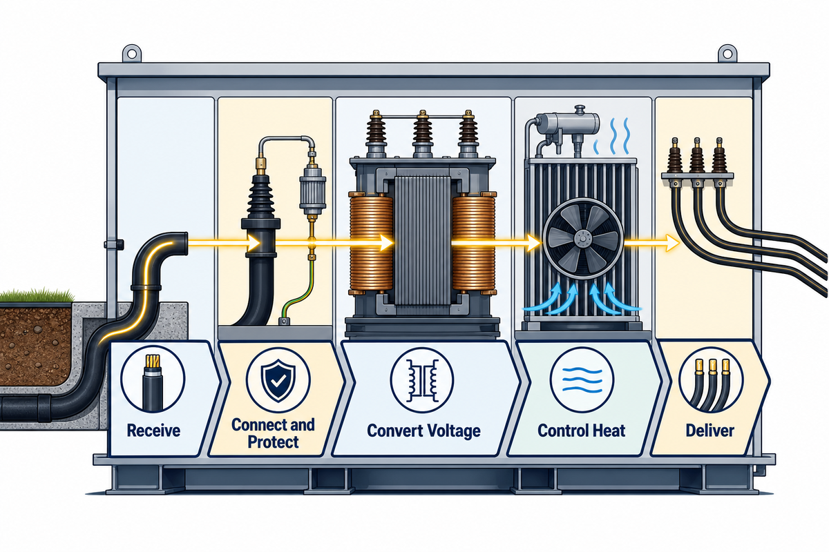
At a high level, a pad-mounted transformer changes voltage by electromagnetic induction. Alternating current in the primary winding creates a changing magnetic flux in the core. That flux induces voltage in the secondary winding. The winding turns ratio establishes the nominal voltage relationship, while the unit’s impedance, loading, temperature and connected system affect real operating conditions.
The cabinet is not the electrical principle; it is the protected package that joins the transformer to an underground distribution system. A useful mental model is the 9-Component Energy Chain. It follows energy from the incoming circuit to the outgoing secondary conductors without pretending every transformer has the same device set.
- Underground primary cable: brings the utility or facility distribution circuit to the transformer location.
- Primary cable interface: makes the cable-to-equipment connection through the specified bushing and connector arrangement.
- Switching interface: may provide an isolation or feeder-routing function when the approved configuration includes it.
- Protective devices: coordinate with the system design to respond to defined abnormal conditions.
- Primary winding: receives electrical energy at the primary voltage.
- Magnetic core: provides the path for the changing magnetic flux shared by the windings.
- Secondary winding: produces voltage at the intended secondary level.
- Dielectric and cooling system: provides insulation and transfers heat according to the unit’s construction.
- Secondary terminals and conductors: connect the transformed supply to downstream distribution equipment.
Primary-side cable interface and switching
The primary compartment can differ greatly from one order to another. Connector style, bushing arrangement, feed scheme, switching provisions and protection must match the serving system and approved drawings. A familiar cabinet shape is not evidence that two units are interchangeable. Even where two nameplates share nominal voltage and kVA, their interfaces or coordination duties may differ.
Core, windings, insulation and heat transfer
The active part carries out the voltage transformation. Electrical losses become heat, so the construction must control temperature within the applicable design and test basis. Liquid-immersed designs use a dielectric fluid as part of the insulation and heat-transfer system. Dry-type designs use a different insulation and cooling approach. Neither label alone answers questions about environmental acceptance, fire requirements, loading or the governing specification.
Secondary terminals and downstream distribution
The secondary side connects to conductors that serve a switchboard, panel system or other downstream distribution equipment. Secondary voltage, conductor arrangement, grounding and protection must agree with the system design. The transformer does not replace downstream overcurrent protection, coordination or site engineering.
The official record for IEEE C57.12.90-2021 helps explain what evidence may be produced for covered liquid-immersed transformers: it lists methods for resistance, ratio, loss, impedance, dielectric, temperature, short-circuit and sound measurements, among other tests. That list shows the difference between an engineering characteristic and a test result. The standard record does not certify every product that mentions it.
Safety boundary: the energy chain is for system understanding. It is not a cabinet-opening, switching, fuse-handling, probing or energization sequence.
Four Configuration Decisions People Often Collapse into “Types”
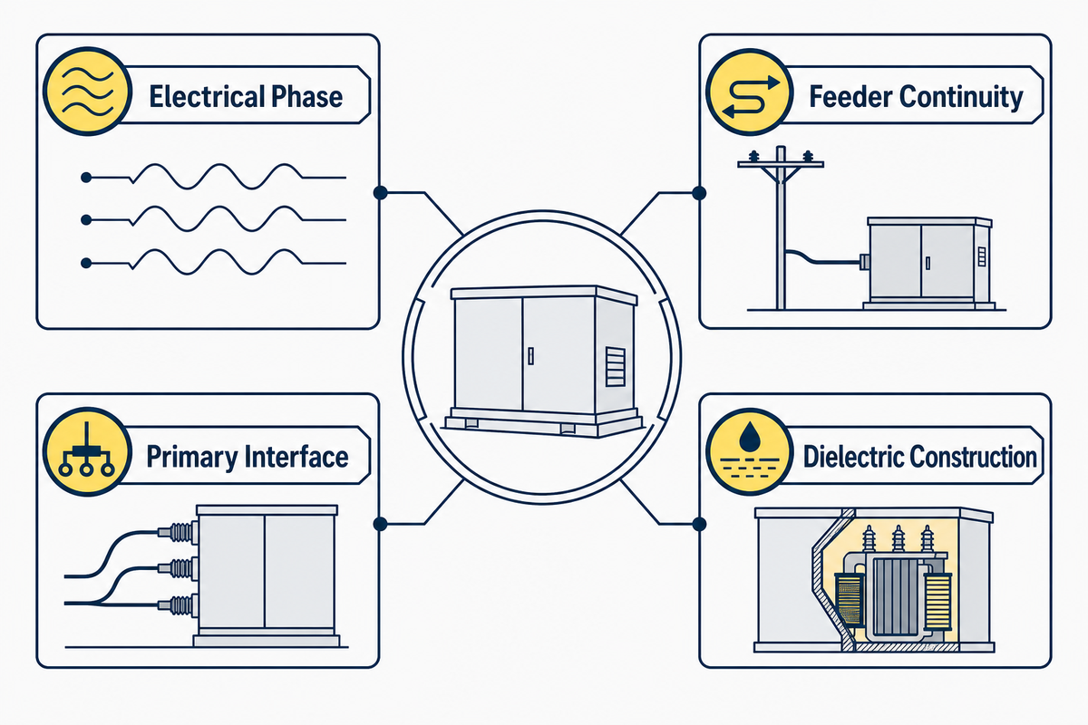
Questions about “types of pad-mounted transformers” often produce a confusing list because several independent design axes are mixed together. Single-phase versus three-phase is not the same question as radial versus loop feed. A dead-front interface does not decide the dielectric system. One project can take one choice from each axis.
The Four-Axis Configuration Compass
1. Electrical phase
Single-phase or three-phase
Single-phase or three-phase
2. Feeder continuity
Radial feed or loop feed
Radial feed or loop feed
3. Primary interface
Live-front or dead-front construction
Live-front or dead-front construction
4. Dielectric/construction
Liquid-filled or dry-type, where applicable
Liquid-filled or dry-type, where applicable
| Axis | Project input | What it changes | What it does not decide |
|---|---|---|---|
| Phase | Source and load system | Winding and connection arrangement | Radial/loop or live/dead front |
| Feed | Feeder topology and continuity plan | Cable routing and switching duties | Phase or insulating medium |
| Interface | Utility and safety specification | How energized primary parts are presented and connected | Feed topology or kVA |
| Dielectric | Application, environment and governing rules | Insulation and heat-transfer approach | Exact accessory package |
Single-phase versus three-phase
The phase choice comes from the electrical system and load plan. A single-phase unit may serve a single-phase portion of a distribution system; a three-phase unit serves a three-phase system. The choice affects the electrical design, but it does not imply radial or loop feed. For a closer commercial look at one axis, see single-phase pad-mounted transformer configurations.
Radial feed versus loop feed
A radial arrangement supplies the transformer from one direction in the normal system arrangement. A loop arrangement is designed around a feeder path that can continue through the location and may support alternate routing under the approved system plan. “Loop feed” does not promise uninterrupted service by itself. Actual continuity depends on the circuit, switching scheme, protection, operating rules and available source.
Live-front versus dead-front construction
These terms describe the primary interface and how energized parts are presented under the applicable design. They should not be reduced to “unsafe” versus “safe.” Both require controlled access and qualified handling. The utility specification, voltage class, connector system and maintenance approach determine what is acceptable.
What are the two types of distribution transformers? The question is incomplete until the comparison axis is named. A phase comparison gives single-phase and three-phase. A feeder comparison gives radial and loop. A primary-interface comparison may give live-front and dead-front. Declaring the axis prevents a false either/or choice.
Inside the Enclosure: Components and Protected Interfaces
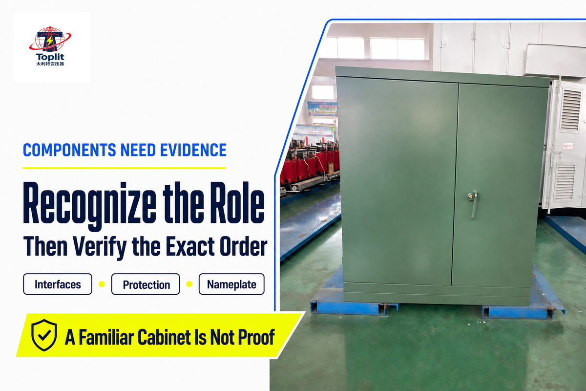
Component names are useful only when they are tied to a function and an evidence request. A generic drawing can teach the arrangement, but it cannot prove what is installed in a specific unit. Switching, protection, connectors, fluids, gauges and accessories vary with the design and order.
| Component group | Role | Why it can vary | Evidence to request |
|---|---|---|---|
| Enclosure and barriers | Restrict access and separate compartments | Public exposure, environment and specification | Approved outline drawing and applicable enclosure requirements |
| Bushings and connectors | Provide the cable interface | Voltage class, cable system and utility practice | Interface schedule and approved drawing |
| Switches and fuses | Support the approved switching and protection scheme | Coordination study and feeder design | One-line diagram, device data and coordination record |
| Core and windings | Transfer energy between voltage levels | Rating, impedance, losses and design | Datasheet, nameplate and applicable test report |
| Dielectric/cooling system | Insulate and transfer heat | Construction and application requirements | Model/order data and fluid documentation where applicable |
| Secondary terminals | Connect the secondary system | Voltage, current and conductor plan | Terminal arrangement and cable schedule |
| Grounding provisions | Provide equipment connection points within the grounding design | Utility, code and site requirements | Approved grounding design and equipment drawing |
| Indicators, labels and nameplate | Communicate identity, ratings and selected conditions | Specified accessory and marking package | Approved nameplate and accessory schedule |
A steel cabinet, a familiar handle or a recognizable connector does not authorize access. “Tamper resistant” also needs context. The official record for IEEE C57.12.28-2023 covers coating-integrity requirements and conformance tests for above-grade pad-mounted enclosures containing apparatus energized above 600 V where the enclosure may be exposed to the public. It is one scope example, not a blanket statement about every aspect of a transformer.
What Must Be Known Before a Project Specification Is Complete?
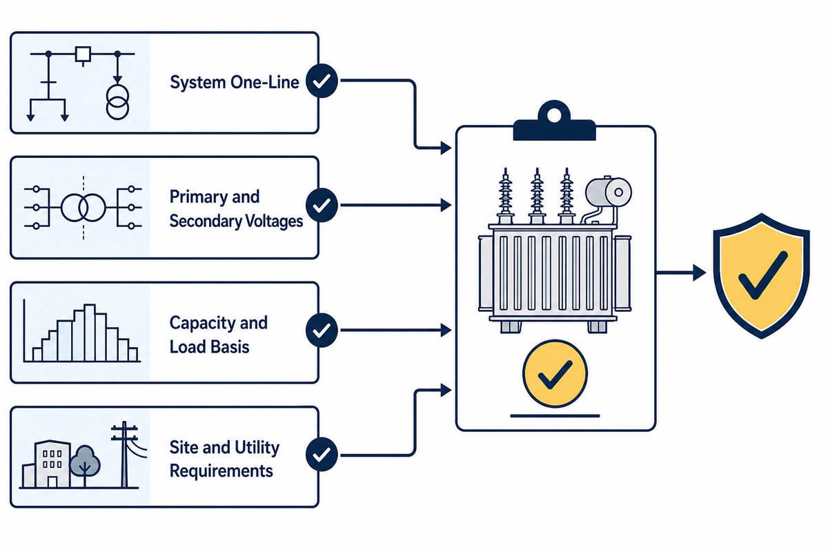
A useful transformer request starts with the system and site, not a copied model number. The supplier cannot safely fill in missing utility, voltage, coordination or civil decisions by guesswork. The project team should turn unknowns into named hold points.
| Input | Typical decision owner | Evidence | If unresolved |
|---|---|---|---|
| Jurisdiction and serving utility | Owner/engineer with utility | Service requirements and adopted rules | The equipment may be unacceptable at the point of service |
| System one-line and phase | Electrical engineer/utility | Approved one-line diagram | Connections and protection cannot be resolved |
| Primary and secondary voltages | Electrical engineer/utility | System data and service approval | The turns ratio and interfaces remain undefined |
| Capacity basis and load profile | Electrical engineer/owner | Load study, diversity basis and growth assumptions | A generic kVA chart may misstate duty |
| Impedance and coordination | Electrical engineer/utility | Fault and coordination study | Fault duty and protective-device behavior remain uncertain |
| Radial/loop and primary interface | Utility/engineer | Feeder plan and interface schedule | Cable routing and compartment arrangement may be wrong |
| Environment and enclosure duty | Owner, civil designer and engineer | Site data and project specification | Corrosion, flooding, access or thermal constraints may be missed |
| Efficiency and loss basis | Engineer/procurement | Applicable rule and loss evaluation method | Bids may not be compared on the same basis |
| Drawings, tests and documents | Project team and supplier | Submittal register and inspection/test plan | Claims cannot be traced to acceptance evidence |
| Schedule and responsibility boundary | Owner/procurement/project manager | Milestone plan and responsibility matrix | Approval, delivery and site work may drift apart |
Capacity selection cannot be reduced to a universal square-foot or connected-load table. The design needs a defensible load basis, diversity assumptions, duty cycle, starting or cyclic loads where relevant, planned growth, environmental conditions and the serving system’s limits. The responsible engineer also checks fault current, protection, voltage regulation and conductor duties.
Once these inputs are defined, the pad-mounted distribution transformer solutions page is the right commercial handoff for configuration discussion. That page should own supplier capabilities and inquiry details; this guide remains the place for learning how to frame the decision. For broader service context, see utility transformer project requirements.
A good inquiry is not the longest inquiry. It is the one that separates confirmed requirements, supplier-variable fields, alternatives that need approval and open decisions with named owners.
Standards, Test Codes, Efficiency Rules and Product Evidence
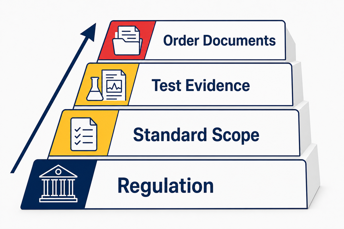
“Meets standards” is too broad to review. A regulation, a design standard, a test code, a laboratory mark and an order-specific report answer different questions. The safest way to read a claim is to ask: which requirement, for which product, in which jurisdiction, supported by which current document?
The Evidence Hierarchy
- Regulation: establishes a legal definition, minimum requirement or compliance date within a jurisdiction.
- Standard scope: establishes design requirements, interface rules or test methods within its stated coverage.
- Test evidence: records results produced for a specific specimen, design, model or order under an applicable method.
- Order documents: connect the approved drawing, datasheet, nameplate, exceptions, certificates and reports to what will be supplied.
| Claim | Strongest useful evidence | What it still does not prove |
|---|---|---|
| “This equipment class is covered by a U.S. efficiency rule.” | Current regulation plus exact product classification | That a particular unit’s submitted values are correct |
| “The enclosure is evaluated to an IEEE requirement.” | Applicable standard edition and model/order conformity evidence | Compliance with unrelated electrical or site requirements |
| “Transformer tests follow IEEE C57.12.90.” | Test report identifying unit, method, values and acceptance basis | A general third-party product certification |
| “The product is NRTL certified.” | Correct mark, recognized standard scope, issuing site and model linkage | Acceptance for every jurisdiction or every configuration |
Read the current regulation before the overview
There is a live discrepancy worth making visible. Current 10 CFR 431.192 states capacity ranges up to 5,000 kVA for the covered liquid-immersed and dry-type categories. The Department of Energy’s distribution-transformer overview still summarizes the upper boundary as 2,500 kVA. For the current legal definition, use the eCFR text rather than silently carrying forward the older overview number. The mismatch does not establish a supplier’s product range.
Efficiency has a defined load basis
Minimum efficiency is not a free-floating “full load” number. Current 10 CFR 431.196 uses a 50 percent nameplate-load basis for the listed liquid-immersed and medium-voltage dry-type tables and a 35 percent basis for the listed low-voltage dry-type tables. It also separates current requirements from amended standards that apply to covered equipment on and after April 23, 2029. A bid review should state the applicable equipment class, date and comparison basis.
A test code is not a product certificate
IEEE C57.12.90 describes test methods within its scope. IEEE C57.12.28 addresses a defined enclosure topic. Neither official scope page proves that a named transformer passed every applicable requirement. That proof must come from documents tied to the exact model or order, with the applicable edition, measured result and acceptance basis visible.
Similarly, the U.S. Occupational Safety and Health Administration explains that where Nationally Recognized Testing Laboratory approval is required, proper certification depends on the registered mark, the product being within the recognized test-standard scope and certification coming from a recognized site. A laboratory name in a brochure or a company-level certificate does not settle those points. See the official OSHA NRTL FAQ.
Site Drawings and Responsibility Handoffs Before Energization
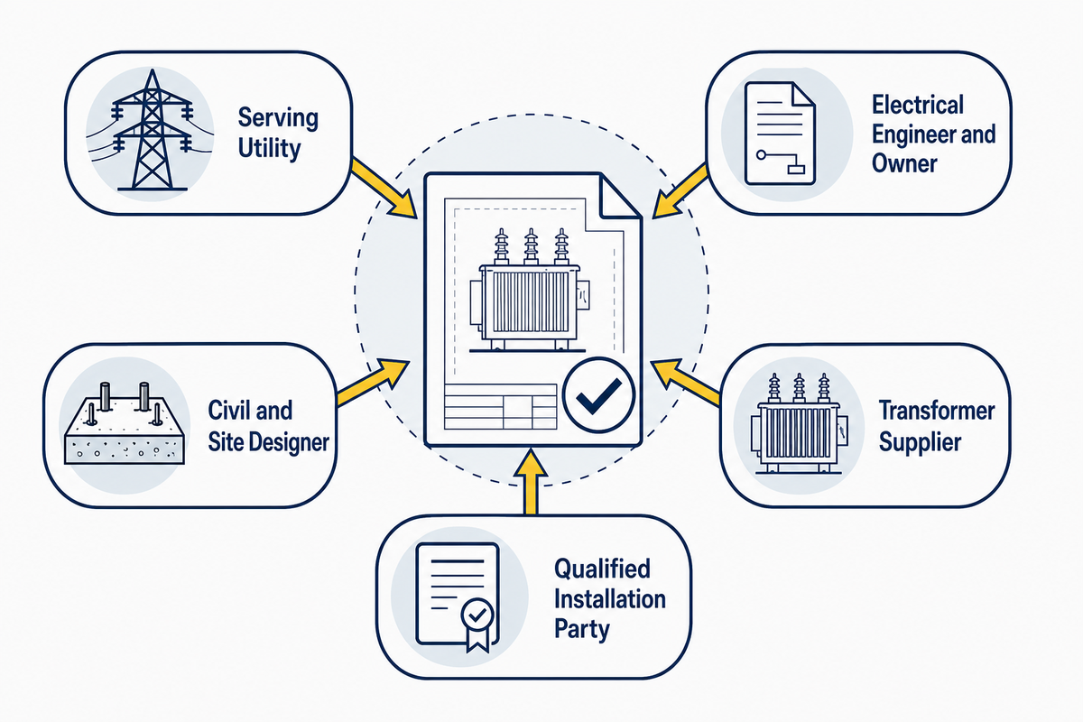
The transformer is only one part of the installation. The foundation, cable entries, grounding, access, drainage, vehicle exposure, lifting route and utility interface must fit both the equipment and the site. A catalogue outline can support early planning, but it is not a substitute for the approved project drawing.
The 5-Seat Responsibility Relay
A decision moves safely only when its owner, approver and evidence are visible.
Serving utility → electrical engineer/owner → civil/site designer → transformer supplier → qualified installer and commissioning party
| Input | Primary contributor | Approver | Hold-point evidence |
|---|---|---|---|
| Service and feeder arrangement | Utility and electrical engineer | Serving utility/project authority | Approved one-line and service letter |
| Pad, conduits and cable window | Civil designer with supplier data | Engineer and utility as required | Approved equipment and foundation drawings |
| Grounding design | Electrical engineer | Authority/utility under project rules | Grounding details and inspection record |
| Access, vehicle protection and drainage | Civil/site designer | Owner and applicable authorities | Coordinated site plan |
| Equipment interfaces and submittals | Supplier | Engineer/utility | Approved drawing, datasheet and exceptions list |
| Installation, testing and energization | Qualified parties | Utility/authority named by the project | Inspection, test and authorization records |
How close can a pad-mounted transformer be to a building? There is no responsible universal distance for an international guide. The answer may depend on the serving utility, adopted electrical and fire rules, equipment construction, doors and openings, working space, vehicle exposure, drainage, fire-resistance conditions and local authority. Use the project’s approved utility and site drawings.
The same rule applies to concrete-pad dimensions. Final dimensions must be coordinated with the exact equipment outline, cable-entry area, local structural conditions and utility requirements. A copied dimension can misalign conduits, restrict door operation or leave the supplied unit unsupported.
Hard hold point: no one should infer permission to install, terminate, test or energize from a general article. The approved project procedure and named authority control those actions.
Public Safety, EMF Context and Warning Signs
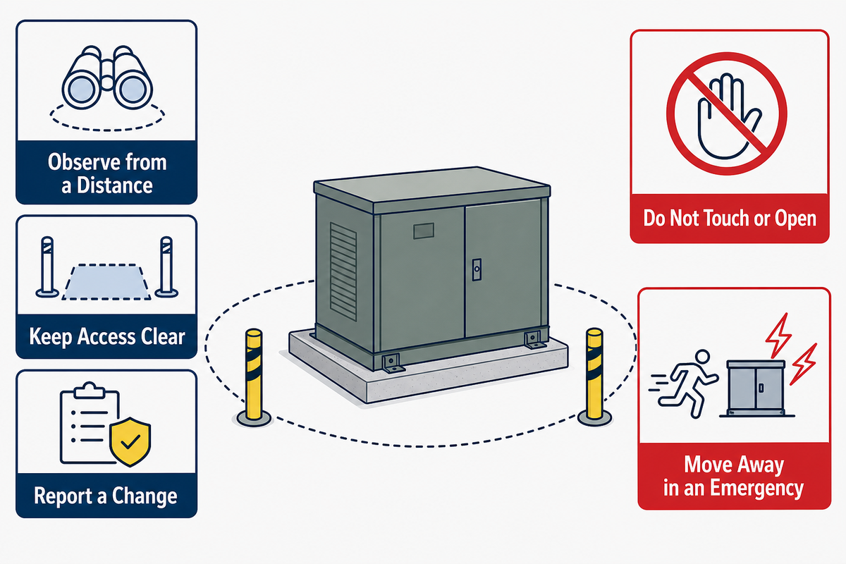
A pad-mounted transformer can be located in residential, commercial or public-access settings because its enclosure and site are designed around controlled access. That does not make the cabinet public furniture. Do not sit on it, climb on it, plant against it, block its doors or allow children to play around it.
The safest public action is observation from a distance and escalation to the serving utility when something changes. The 10-Signal Safe-Observation Board below avoids diagnosis. One observation can have several causes; trained people determine the cause.
1. Damaged door or lock
Keep away and report loss of secure access.
Keep away and report loss of secure access.
2. Visible fluid or oily residue
Do not touch it; keep people and animals away.
Do not touch it; keep people and animals away.
3. Smoke or fire
Move away and call emergency services and the utility.
Move away and call emergency services and the utility.
4. New or sharply changed sound
Report the change without approaching to investigate.
Report the change without approaching to investigate.
5. Vehicle or impact damage
Assume hidden electrical damage may exist.
Assume hidden electrical damage may exist.
6. Exposed or displaced cable
Stay clear and prevent access if that can be done safely.
Stay clear and prevent access if that can be done safely.
7. Floodwater around the unit
Do not enter the water or touch nearby metalwork.
Do not enter the water or touch nearby metalwork.
8. Severe corrosion or open seam
Report the enclosure condition.
Report the enclosure condition.
9. Missing warning labels
Tell the utility; do not replace labels yourself.
Tell the utility; do not replace labels yourself.
10. Signs of tampering
Keep away and report promptly.
Keep away and report promptly.
Is it safe to live next to a pad-mounted transformer?
The question combines electrical access, fire/site design and electromagnetic-field concerns. Each needs its own evidence. Enclosure integrity, utility access, local clearances and the condition of the site matter for physical safety. An undamaged locked cabinet at an approved site is different from a damaged or obstructed unit.
For electric and magnetic fields, the Australian Radiation Protection and Nuclear Safety Agency states that there is no established evidence that fields from a substation or transformer cause health effects. It also says fields from typical small distribution substations are generally indistinguishable from normal household background beyond roughly 5–10 metres. That is exposure context from an Australian government health authority; it is not a universal building clearance or permission to ignore local utility rules. Read the source in ARPANSA’s electricity and EMF FAQ.
| Observation | Safe response | Do not |
|---|---|---|
| Normal cabinet, no visible change | Keep required access clear and follow site rules | Touch, climb, decorate or obstruct it |
| Damage, leak, flood or tampering | Stay away and contact the utility | Open, inspect closely or touch leaked material |
| Smoke, fire or exposed conductor | Move away; call emergency services and the utility | Approach or attempt electrical firefighting without authority and training |
Maintenance Records, Failure Signals and Lifecycle Planning
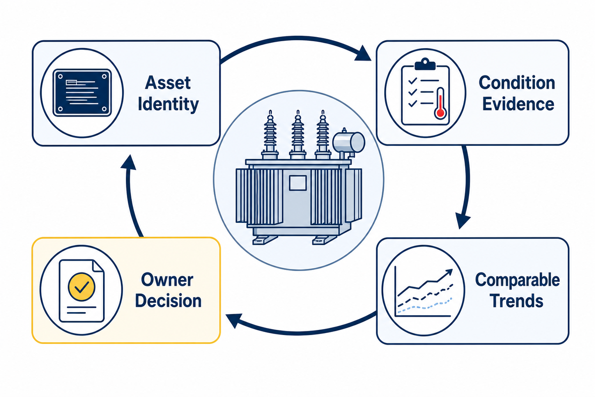
There is no single maintenance interval or service-life number that fits every pad-mounted transformer. Responsibility may sit with a utility, a facility owner or another asset manager. The program depends on equipment type, manufacturer instructions, loading, environment, criticality, governing rules and observed condition.
A sound lifecycle record links identity, condition and decisions. It should preserve the nameplate and drawing relationship; installation and commissioning records; loading and outage history; inspection findings; leak or fluid records where applicable; qualified electrical or thermal assessment records; protection events; repairs; and the reason for each next-review or replacement decision.
| Evidence | Trend question | Decision owner | Next trigger |
|---|---|---|---|
| Nameplate, drawings and asset ID | Do all records refer to the same unit and revision? | Asset owner | Any document mismatch or equipment change |
| Load and outage history | Has duty changed from the design basis? | Owner and electrical engineer | Growth, repeated events or operating change |
| Condition observations | Is a condition stable, recurring or worsening? | Utility/qualified maintenance party | Change from the accepted baseline |
| Qualified test or diagnostic results | Do comparable results show a meaningful trend? | Qualified engineer/asset owner | Threshold set by the governing program |
| Spares and replacement plan | Can the required configuration be replaced within the risk window? | Asset and procurement owners | Risk, condition or supply change |
What are common problems with padmount transformers?
Common padmount transformer concerns are easier to assess when observable conditions are separated from diagnostic categories. The public may see enclosure damage, a leak, corrosion, flooding, noise that has clearly changed or collision evidence. Qualified teams may investigate connections, protection, insulation, cooling, loading or internal electrical condition under the approved program. A visible symptom does not identify a failed component, and the absence of a visible symptom does not prove internal health.
How long does one last? Age alone is not a verdict. Design, manufacturing, loading, environment, events and maintenance history all matter. Use condition and risk evidence rather than a universal 25-, 30- or 40-year promise. Replacement planning should also consider whether drawings, interfaces and an acceptable equivalent can be recovered before an urgent need arises.
Why Specification Discipline Matters as Lead Times Grow
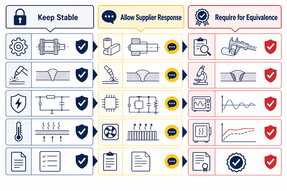
A precise specification is not only an engineering record. It is also the basis for reviewing alternates without losing required interfaces, evidence or approvals. A specification that mixes fixed system needs with brand-specific habits makes equivalent-bid review harder. A specification that leaves critical interfaces blank pushes rework into submittals and site coordination.
The U.S. Department of Energy reported that distribution-transformer lead times increased from about 3–6 months in 2019 to 12–30 months in 2023. The same DOE supply-chain page described more than 80,000 varieties and discussed specification fragmentation. These are dated market observations, not a current delivery quote. They show why reusable requirements, clear exceptions and early drawing review matter when supply is constrained. See DOE’s supply-chain and market analysis.
| Keep stable | Allow supplier response | Require for equivalence |
|---|---|---|
| System voltages, phase, frequency and interface duties | Design details that meet the stated duty | Completed datasheet and deviations list |
| Applicable rules, test basis and approval path | Proposed evidence package and schedule | Standard editions, reports and document mapping |
| Site envelope, access and civil interfaces | Exact outline within approved constraints | Coordinated drawing with cable and foundation interfaces |
The practical goal is not to make every supplier build the same transformer. It is to make every bid answer the same project questions. Then the project team can distinguish a genuine equivalent from a change that needs engineering or utility approval.
Frequently Asked Questions
What is a pad-mounted distribution transformer?
A pad-mounted distribution transformer is a locked, ground-level transformer assembly connected to underground distribution cables. It receives power at a primary distribution voltage and supplies a lower-voltage secondary system. The name does not establish phase, radial or loop feed, live-front or dead-front interface, dielectric system, rating or accessory package. Those details come from the system, utility and approved project specification.
How does a pad-mounted transformer work?
Alternating current in the primary winding creates changing magnetic flux in the core. That flux induces voltage in the secondary winding according to the turns relationship. The enclosure packages the active part with cable interfaces, protection and other specified devices for a ground-level underground-distribution application. The explanation is conceptual; operation and testing require qualified people and approved procedures.
What is the difference between radial feed and loop feed?
Radial and loop describe feeder topology, not transformer phase. A radial arrangement normally supplies the transformer from one direction. A loop arrangement supports a feeder path through the location and may permit alternate routing under the approved circuit design. Actual service continuity still depends on sources, switches, protection and operating rules.
What is the difference between live-front and dead-front construction?
The terms describe the primary interface and the presentation of energized parts within the applicable design. They do not mean “dangerous” and “safe,” and neither authorizes public access. The utility’s voltage class, connector system, operating practice and equipment specification determine which construction is accepted.
Are pad-mounted transformers safe in residential areas?
Pad-mounted transformers are designed for controlled access in locations that may be accessible to the public, but safety depends on an approved site, secure enclosure, clear working access and sound condition. People should not touch, climb on or obstruct them. Damage, leaks, flooding, smoke, fire, exposed cables or tampering should be reported from a safe distance.
What warning signs should be reported to the utility?
Report damaged doors or locks, visible fluid, smoke, fire, collision damage, exposed or displaced cables, flooding, severe corrosion, missing warnings, tampering or a clearly new sound. Do not touch the enclosure or leaked material and do not open the cabinet. For smoke, fire or exposed conductors, move away and contact emergency services as well as the utility.
How close can a pad-mounted transformer be to a building?
No single distance applies everywhere. The serving utility, adopted electrical and fire rules, equipment construction, building openings, working space, vehicle exposure, drainage and local authority can all affect placement. Use the exact project’s approved utility and site drawings; do not transfer a setback from an unrelated project.
How long does a pad-mounted transformer last?
There is no universal service-life promise. Loading, temperature, environment, manufacturing, events, maintenance and condition all influence risk. Asset owners should use identity records, load and outage history, inspections, qualified assessments and replacement lead time to make a condition-based decision rather than replacing or retaining equipment on age alone.
Does an IEEE reference prove that a specific transformer is certified?
No. An IEEE reference may identify design requirements or a test method within a stated scope. Proof for a specific product needs model- or order-linked documents that identify the applicable edition, test or conformity evidence and acceptance basis. IEEE C57.12.90, for example, is a test code, not a general product certificate.
What should be prepared before requesting a configuration review?
Prepare the jurisdiction and utility, system one-line, phase and frequency, primary and secondary voltages, load basis, impedance and coordination needs, feed scheme, primary interface, site conditions, efficiency basis, accessories, required drawings and tests, schedule and open decisions. Mark assumptions clearly so the supplier can return exceptions instead of silently filling gaps.
References & Sources
- 10 CFR 431.192 — Definitions
- 10 CFR 431.196 — Energy conservation standards and compliance dates
- IEEE C57.12.28-2023 official scope record
- IEEE C57.12.90-2021 official scope record
- U.S. Department of Energy — Distribution Transformers
- U.S. Department of Energy — Supply Chain and Market Analysis
- ARPANSA — Electricity and EMF FAQs
- OSHA — NRTL Program FAQs
Editorial transparency: this guide separates public sources from product-specific evidence. The organization link identifies the Talite technical team; it does not claim a named author, field inspection or customer case that is not documented here.
Turn Project Unknowns into a Reviewable Input List
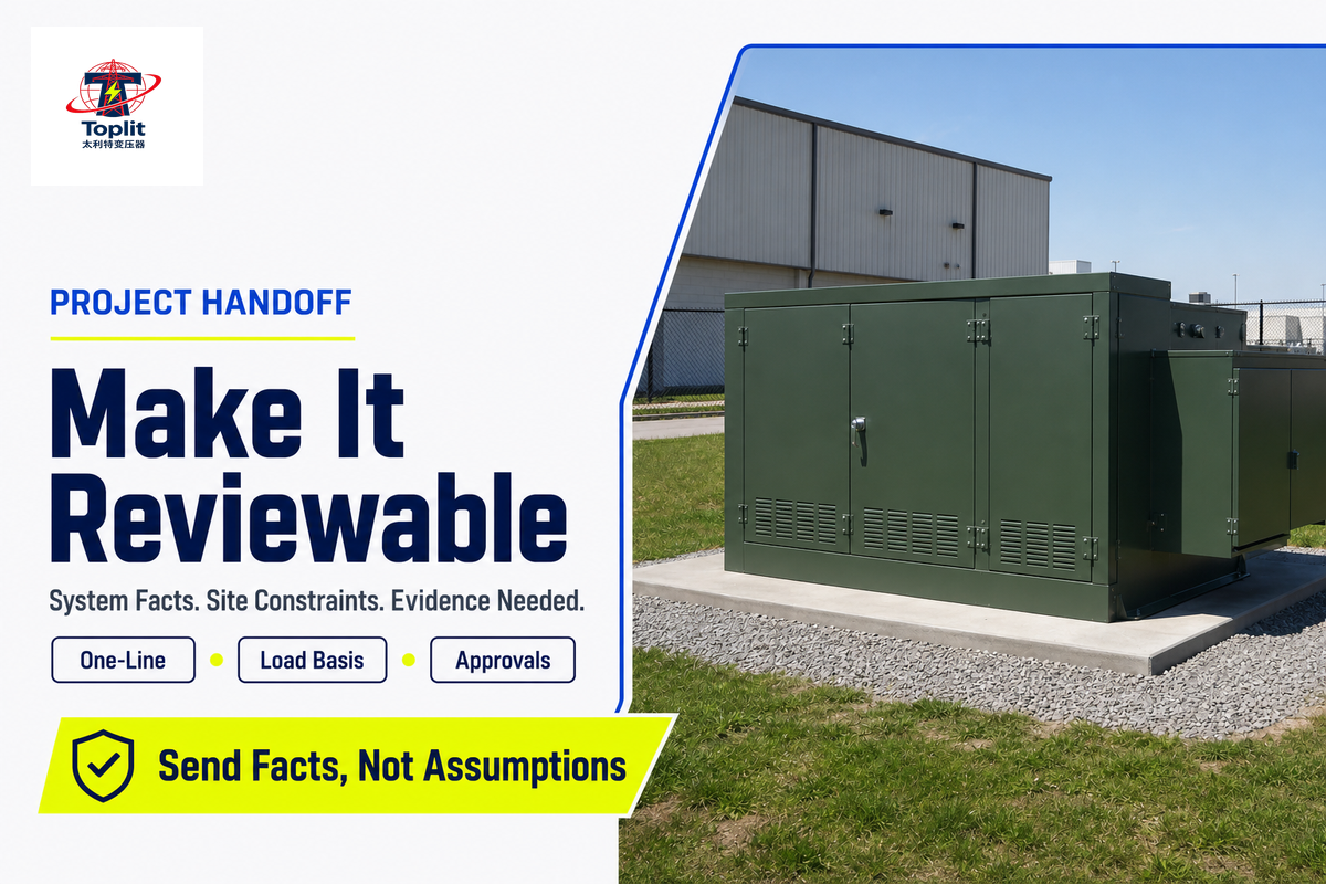
Bring the system one-line, voltages, phase, load basis, feeder arrangement, site constraints, utility requirements and document expectations. The discussion can then focus on gaps, exceptions and the evidence needed for approval.
![Single Phase Pad Mounted Transformer Guide [2026]](https://toplit-transformer.com/wp-content/uploads/2026/08/single-phase-pad-mounted-transformer-guide-featured-1-150x150.png)