Get in touch with Talite Transformer Co., Ltd Company

Updated August 2026
Distribution transformer protection is the coordinated process of detecting an abnormal condition, deciding whether it belongs inside a protected zone, interrupting the correct path, and verifying the result. A fuse, relay, surge arrester, sensor, or pressure device can cover a defined condition, but no single component proves that the transformer and surrounding electrical system are selectively protected.
Direct answer: Distribution transformer protection maps each credible abnormal condition to a sensing input, protective function, interrupting device, isolated zone, and evidence owner. Final settings depend on project fault levels, grounding, transformer construction, operating modes, utility rules, and approved coordination studies.
Quick specs to collect before a protection study
- Transformer kVA or MVA rating, primary and secondary voltage, winding connection, impedance, and grounding arrangement
- Normal, alternate, islanded, and reconfigured operating modes, including generation or storage sources
- Available fault current, current-transformer data, breaker or fuse curves, interrupting duty, and trip-supply details
- Construction type, oil system, sensor locations, alarms, trips, communications, and environmental-screening owner
- Study revision, drawings, test records, settings file, approvers, change history, and post-energization review owner
Key points
- Define the fault zone before choosing the type of protection.
- Coordinate legitimate load, inrush, damage limits, fault current, and adjacent-device curves without copying a universal setting.
- Treat surge protection as a physical path that includes arrester placement, conductors, bonding, and grounding.
- Release settings only after every input, test, drawing, approver, and change trigger has an owner.
What Distribution Transformer Protection Must Do
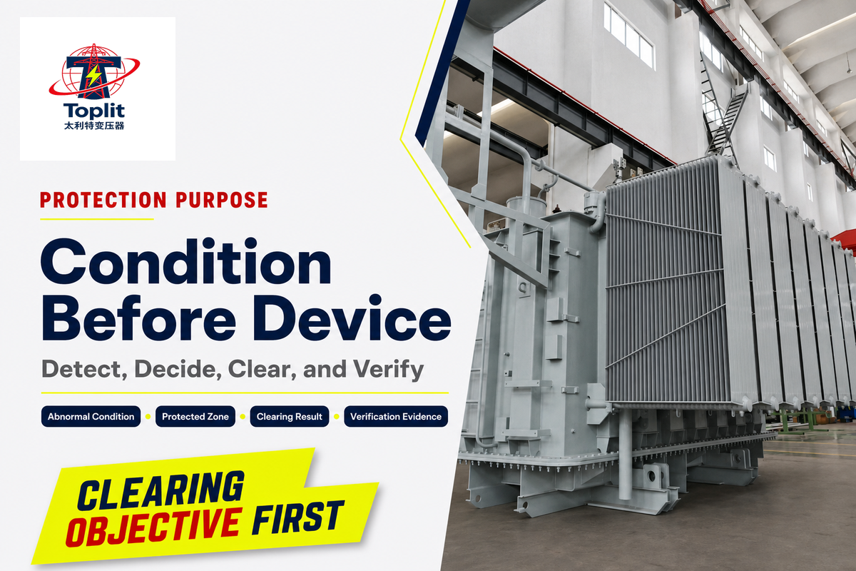
Transformer protection must detect an abnormal condition, decide whether it belongs inside the protected zone, operate the correct interrupting device, and leave enough evidence to verify the result. The objective is controlled clearing with appropriate selectivity, not the largest possible collection of protective devices.
Primary fusing can address selected overcurrent conditions, yet it doesn’t measure oil temperature, identify every internal fault, shorten an unsuitable surge path, or confirm that a downstream circuit breaker clears selectively. The active IEEE C37.91-2021 guide scope itself spans current-transformer behavior, transformer faults, clearing, and re-energization. That breadth is why a device list is an incomplete starting point.
| Condition | Question to answer | Limitations / not suitable for |
|---|---|---|
| Overload | Is the thermal duty temporary, expected, or damaging? | A current threshold alone cannot describe accumulated thermal duty. |
| External short circuit | Which upstream or downstream device should clear? | Do not infer transformer-zone ownership from current magnitude alone. |
| Internal winding fault | Which measurements define the internal zone? | A primary fuse may not distinguish all internal faults. |
| Earth fault | What grounding path and sensor placement exist? | Function labels do not prove zero-sequence sensitivity. |
| Overvoltage or surge | What is the complete arrester-to-ground path? | Overcurrent protection does not replace insulation coordination. |
| Overheating | Where is temperature measured and what owns the response? | One sensor may not represent winding, oil, and ambient conditions. |
| Gas, pressure, or oil abnormality | Does the physical construction support the function? | Not applicable to every dry, sealed, or conservator design. |
| Protection type | Primary decision | Limitations / not suitable for |
|---|---|---|
| Primary overcurrent | Coordinate source-side fault and damage duties | Does not cover every internal or non-electrical condition. |
| Secondary overcurrent | Separate feeder and transformer-zone clearing | Needs downstream curves and retained-service priorities. |
| Differential | Define the internal measurement zone | Application depends on CT and transformer data. |
| Restricted earth fault | Define the grounded-winding fault zone | Cannot be separated from grounding and neutral sensing. |
| Surge protection | Control the arrester-to-ground path | Does not replace overcurrent or internal-fault protection. |
| Thermal protection | Relate loading and temperature evidence | Sensor and model applicability must be known. |
| Gas or pressure protection | Match the physical construction | Not transferable to every sealed, conservator, or dry design. |
| Monitoring and diagnostics | Preserve valid event evidence | Does not establish selectivity or fault duty. |
A useful way to compare types of transformer protection is by abnormal condition and zone, not by catalog category. That keeps transformer protection devices subordinate to the protection scheme instead of treating the device list as the design.
Key takeaway: Name the condition and desired clearing result before naming hardware. A buyer who starts with “which fuse?” has skipped the transformer failure mode, protected zone, and retained-service decision.
Map the Fault Zone Before Choosing a Device
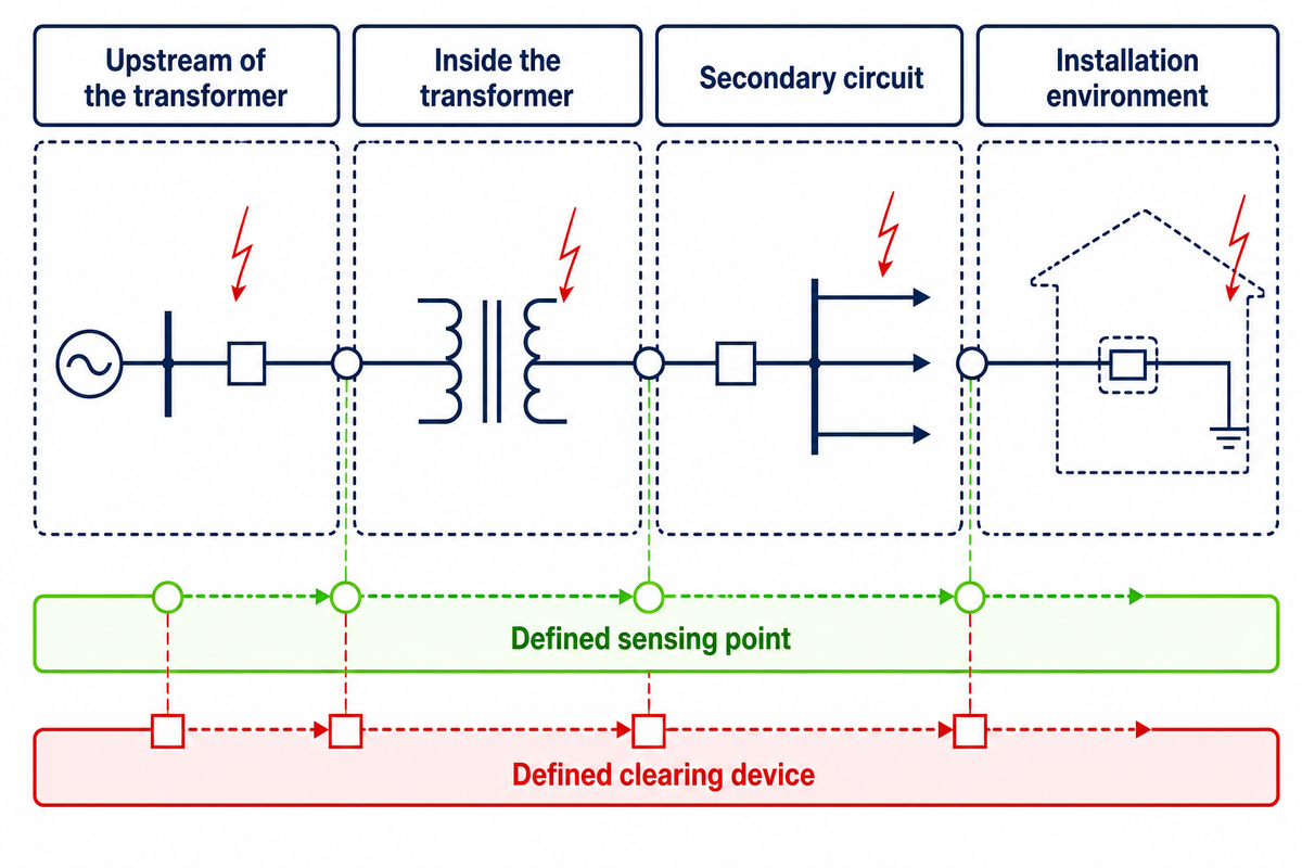
A fault-zone map separates conditions upstream of the transformer, inside the transformer, on the secondary circuit, and in the installation environment. Each zone needs a defined sensing point and a clearing device. Transformer winding faults and phase to earth faults may need dedicated protection with different measurement boundaries. Otherwise, two devices may trip for the same fault while another condition has no effective clearing path.
Fault-Zone Clearing Responsibility Trace
The Fault-Zone Clearing Responsibility Trace links abnormal condition, sensing, decision, interruption, isolation, retained service, and verification evidence.
| Condition | Sensing input | Function | Clearing path | Evidence owner | Limitations / not suitable for |
|---|---|---|---|---|---|
| Primary external fault | Utility-side current and status | Upstream protection | Utility interrupter | Serving utility | Transformer supplier cannot set the utility zone alone. |
| Transformer internal phase fault | Zone current measurements | Application-dependent differential or overcurrent | Assigned breaker or fuse | Protection engineer | Requires verified CT arrangement and transformer connection. |
| Restricted earth fault zone | Phase and neutral current path | Application-dependent REF | Assigned breaker | Protection engineer | Not separable from grounding and CT placement. |
| Secondary feeder fault | Feeder current and breaker status | Downstream overcurrent | Feeder breaker or fuse | Facility engineer | Do not clear the whole transformer where a feeder can isolate selectively. |
| Thermal overload | Current, temperature, and loading history | Alarm, trip, or operating response | Assigned control or breaker | Owner engineer | Sensor location and thermal model must be documented. |
| Surge at transformer terminal | System and insulation-coordination inputs | Voltage limitation | Arrester and ground path | Utility or design engineer | Nameplate selection alone does not control conductor path. |
| Pressure or gas event | Construction-specific device | Alarm, pressure relief, or trip | Assigned control or interrupter | Transformer and protection engineers | Physical applicability must be confirmed before specification. |
| Monitoring alarm | Sensor, timestamp, and health status | Investigate and classify | No automatic clearing unless designed | Diagnostic owner | An alarm is evidence, not a final diagnosis. |
| Post-change mismatch | Revision and configuration records | HOLD or RE-STUDY | Release authority | Owner and commissioning team | A passed device test cannot validate an obsolete study basis. |
One common objection is that the device list already shows who owns the fault. It doesn’t. Current-transformer placement can fall outside the intended zone, the breaker can sit beyond the equipment boundary, and a downstream feeder may be the selective clearing point. The public scope of IEEE C37.91-2021 includes current-transformer performance, transformer faults, clearing, and re-energization, but it does not supply project settings. The matrix forces the protection engineer, owner, and utility to expose those handoffs before the settings file exists.
Key takeaway: Draw the sensing boundary and the clearing boundary on the same one-line diagram. If they don’t enclose the same intended zone, the function description is incomplete.
Overcurrent and Fuse Protection: Coordinate, Do Not Guess
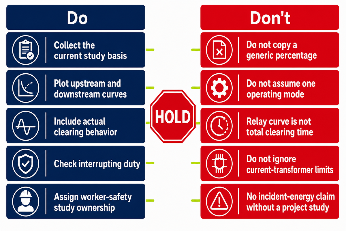
Overcurrent protection must ride through legitimate transformer behavior while clearing damaging current within the limits of the transformer, conductors, and interrupting devices. On the primary side of the transformer, overload protection and short-circuit protection still require the correct load, inrush, damage, fault-current, and clearing evidence. A fuse or relay selection therefore needs full-load current, inrush basis, damage information, available fault current, adjacent curves, interrupting duty, and actual breaker clearing behavior.
A transformer overcurrent protection review begins with a current basis, then tests it against inrush, damage, fault, clearing, and selectivity evidence. kVA and voltage alone can’t show that full coordination problem. The NFPA 70 overview explains the code framework, while the adopted edition and authority having jurisdiction determine project obligations. A protection study must also use utility criteria and equipment data. This article supplies no universal fuse size, pickup, or time delay.
Consider a facility replacement where procurement knows the transformer rating and primary voltage, but the alternate feed, downstream breaker curve, source fault contribution, and transformer damage information are still open. Choosing a fuse from the two known fields would turn four missing inputs into hidden assumptions. The defensible action is HOLD: assign the utility fault-current record, collect both operating modes, obtain the equipment curves, and name the engineer who approves selectivity. The commercial schedule may continue, but the setting release can’t.
Do
- Collect the current study basis
- Plot upstream and downstream curves
- Include actual clearing behavior
- Check interrupting duty
- Assign worker-safety study ownership
Don’t
- Copy a percentage from a generic table
- Assume one operating mode
- Treat a relay curve as total clearing time
- Ignore current-transformer limits
- Claim an incident-energy result without a project study
Use the electrical distribution system design record to define sources and downstream topology, and use the transformer kVA sizing guide only for load and rating context. Neither page replaces a coordination study.
Key takeaway: If available fault current, operating mode, damage information, adjacent curves, or interrupting duty is unknown, mark the setting HOLD instead of filling the gap with a rule of thumb.
Surge Arresters and Grounding: The Fastest Path Matters
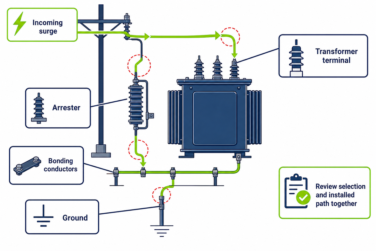
Surge protection depends on the complete path from the incoming surge to the transformer terminal, arrester, bonding conductors, and ground. A suitable arrester nameplate can’t correct excessive physical separation, long conductors, weak bonding, or an unsuitable grounding path. Placement and installation geometry remain part of insulation coordination.
The public CIGRE USNC and AEP presentation models arrester separation together with arrester lead and grounding-conductor length. It addresses high-voltage substation circuit breakers, not distribution-transformer guidance or settings. The transferable point is the general physical mechanism: conductor voltage drop and separation affect the stress that reaches protected equipment. Record system voltage, grounding method, insulation withstand basis, arrester duty, conductor route, and connection points.
Field drawings may show the same arrester model before and after a pole-top layout change, yet the revised conductor path can be different. The label remains unchanged while separation, bonding, and ground routing move. Nameplate-only review would miss the new physical path. The owner should compare the released drawing with the installed route, document deviations, and send material changes back to the engineer responsible for insulation coordination.
The currency check matters too. IEEE lists IEEE C62.22-2009 as Inactive-Reserved and identifies a revision project. Don’t describe that edition as the current active guide. Verify the live standard or project requirement at design release.
Key takeaway: Review arrester selection and the installed connection path together. The procurement objection “the voltage rating matches” doesn’t close the placement, bonding, grounding, or document-control questions.
When Differential and Restricted Earth-Fault Protection Fit
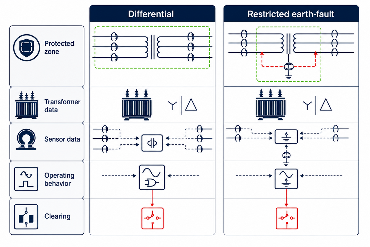
Differential and restricted earth-fault protection fit only when the intended zone, transformer connection, grounding path, current-transformer placement, ratios, classes, and available clearing device support the function. They can add sensitivity for defined internal faults, but a function name doesn’t make the scheme universally required or correctly applied.
Transformer differential protection compares measurements around a defined transformer zone. Its performance depends on the windings of the transformer, current-transformer behavior, ratio matching, polarity, connection compensation, and inrush treatment. Search results may phrase the related function as “restricted earth fault protection of transformer,” but the engineering question is still which grounded winding, neutral path, sensors, and boundaries define its zone. The IEEE transformer-relaying guide provides the application scope; the project study must supply the actual inputs.
| Question | Differential review | Restricted earth-fault review | Limitations / not suitable for |
|---|---|---|---|
| Protected zone | Measurements around transformer zone | Defined grounded-winding zone | Undefined boundaries prevent a defensible application. |
| Transformer data | Winding and vector connection | Grounded winding and neutral path | A generic two-winding label is not enough. |
| Sensor data | CT location, ratio, class, polarity, saturation | Phase and neutral CT arrangement | Relay availability cannot create missing measurements. |
| Operating behavior | Inrush and external-fault stability | Sensitivity within the grounded zone | No universal pickup or restraint setting is implied. |
| Clearing | Breaker or assigned interrupter | Breaker or assigned interrupter | A detection function without a tested trip path cannot clear. |
The objection “differential is the main protection” confuses a common engineering label with universal applicability. Small distribution transformers, pole-mounted units, industrial substations, and larger power transformer installations can have different zones, interfaces, criticality, and utility rules.
Key takeaway: Choose the function only after confirming the transformer, grounding, sensor, and clearing interfaces that make its zone real.
Thermal, Pressure, Gas, and Oil-Level Protection Depends on Construction
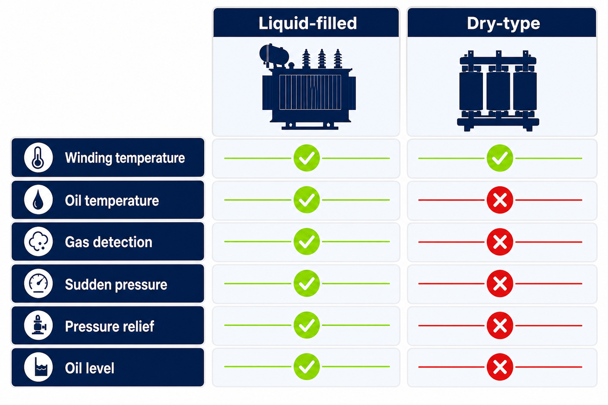
Construction determines which temperature, gas, pressure, oil-level, and relief functions are physically meaningful. Some liquid-immersed designs share device requirements, while a dry-type transformer has no oil level to measure. Start with the tank, preservation system, cooling method, sensor locations, and required alarm or trip response.
Named engineers in Consulting-Specifying Engineer describe gas, pressure, temperature, and related functions as construction-dependent. Treat that material as secondary engineering context, not a universal schedule. The temperature of the transformer, temperature of the oil, winding temperature, thermal time constant, type of cooling, and loading profile may support different responses.
| Function | Applies when | Input and owner | Limitations / not suitable for |
|---|---|---|---|
| Winding temperature | A supported measurement or thermal model exists | Sensor/model record; owner engineer | Do not assume one location represents every winding hot spot. |
| Oil temperature | Liquid-filled construction provides the measurement | Sensor location; transformer supplier and owner | Not a dry type function. |
| Gas detection | The preservation system supports the device | Construction drawing; transformer supplier | Do not copy from a conservator arrangement to every sealed unit. |
| Sudden pressure | Tank construction and device application support it | Device data and trip philosophy; joint review | Exact response remains design-specific. |
| Pressure relief | Liquid-filled tank design requires a relief path | Mechanical design and site safety owner | A relief device is not an electrical clearing function. |
| Oil level | Construction exposes a meaningful level indication | Gauge/sensor record; maintenance owner | Not applicable where no meaningful level indication exists. |
For oil-filled equipment, assign the person who screens spill, containment, fire, and environmental obligations for the actual site. Capacity thresholds and legal duties differ by jurisdiction and installation facts, so this guide doesn’t publish a universal cutoff or claim compliance.
Key takeaway: Copying a device schedule across transformer constructions can specify a function that has no valid sensor, no physical mechanism, or no approved response.
Protection Relays and the Inputs They Actually Need
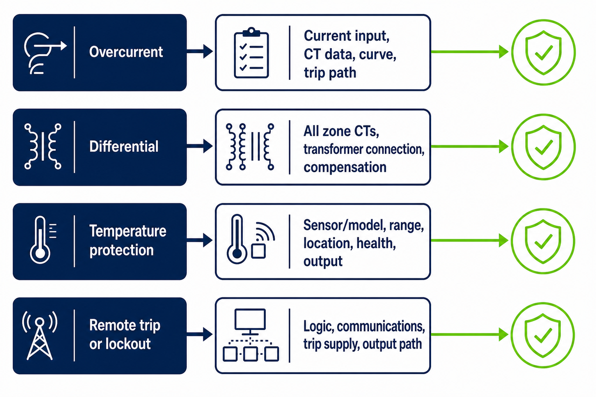
A transformer protection system exists only when real measurements, status inputs, trip power, logic, communications, and an interrupting device support the desired result. Menu labels for voltage protection, a thermal relay, or a thermal overload relay do not prove that the required sensors and trip path exist. Convert every desired relay function into an input-output interface list, then verify polarity, scaling, time quality, logic, trip path, and field configuration.
For each function, identify current in A, voltage in V or kV, temperature in °C where applicable, breaker or switchgear status, trip-supply source, output contact, clearing device, communications dependency, and diagnostic owner. Current-transformer ratio, class, polarity, location, and saturation behavior need verification. NERC’s 2020 Lessons Learned commissioning guidance emphasizes design checks, installation tests, in-service tests, and measured verification; it’s guidance, not a newly adopted mandatory standard.
“An effective quality program will include clear direction on whether engineering, design, or testing personnel are responsible for verification of the accuracy of wiring diagrams.”
| Desired function | Required interface evidence | Release question | Limitations / not suitable for |
|---|---|---|---|
| Overcurrent | Current input, CT data, curve, trip path | Does total clearing coordinate? | Relay time alone omits interrupting-device operation. |
| Differential | All zone CTs, transformer connection, compensation | Are ratios, polarity, and zones verified? | Missing or mismatched measurements invalidate the function. |
| Temperature protection | Sensor/model, range, location, health, output | Who owns alarm and trip response? | No sensor means no measured temperature function. |
| Remote trip or lockout | Logic, communications, trip supply, output path | Has the end-to-end path been tested? | A configured bit is not a proven trip path. |
Key takeaway: Specify the input and clearing interface beside every relay function. The objection “the relay includes it” is answered only by field evidence that the measurement and trip path exist.
Single-Phase Pole-Mounted Transformer Protection Interfaces
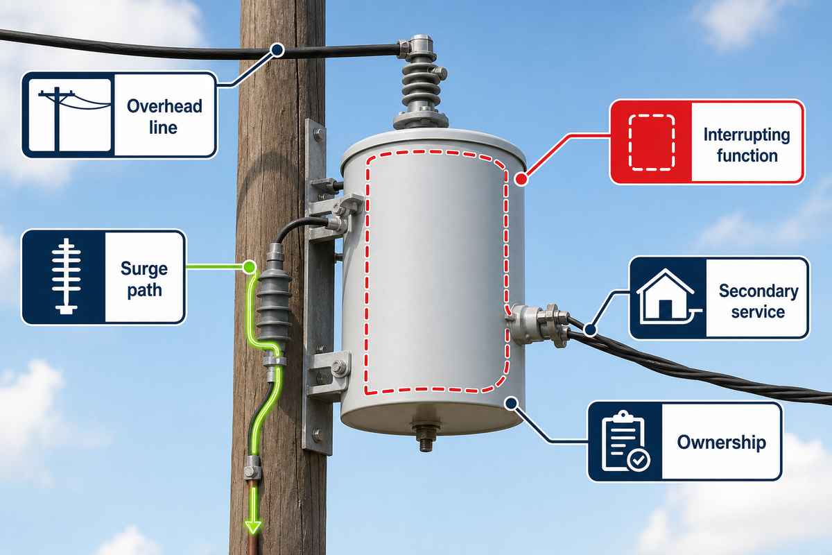
A single-phase pole-mounted arrangement joins the overhead line, transformer, external or integrated interrupting function, surge arrester, grounding, secondary service, and serving-utility rules. The transformer supplier can document product interfaces, but the complete pole-line protection arrangement still needs utility data and project approval.
Talite’s live single-phase pole-mounted transformer page asks buyers to identify conventional or self-protected preference and utility devices. It also leaves utility acceptance and exact interface ownership project-specific. That’s first-party product context, not independent evidence that one arrangement is safe or compliant.
- Overhead line: identify system voltage, grounding, source, fault level, reclosing, and utility criteria.
- Interrupting function: record whether it’s external or integrated and who validates its clearing zone.
- Surge path: confirm arrester duty, location, conductor route, bonding, and grounding.
- Secondary service: document conductors, downstream protection, load, and retained-service objective.
- Ownership: assign drawings, settings, approval, installation, inspection, and maintenance records.
The pole-mounted transformer product family can help route a product inquiry. The pole-mounted transformer request-readiness calculator can expose missing RFQ fields. Neither tool assigns the serving utility’s protection responsibilities.
Key takeaway: A self-protected preference can change the equipment interface, but it doesn’t erase the line, arrester, grounding, service, coordination, and utility-approval boundaries.
Build the Protection Coordination Input Stack
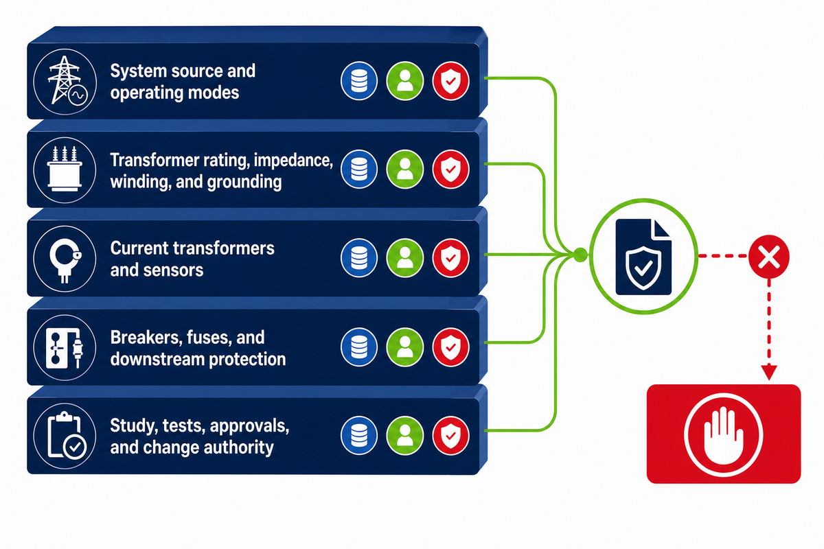
The protection coordination input stack assigns every system, transformer, sensor, interrupting-device, operating-mode, study, and approval record to a named owner. It should connect the high-voltage (HV) system basis, apparent power demand, and actual electrical equipment to the same revision-controlled study. A transformer quotation may be commercially complete while fault current, grounding, current-transformer data, downstream curves, alternate modes, or release authority remains unavailable.
5-Layer Protection Coordination Input Stack
The 5-Layer Protection Coordination Input Stack turns missing study assumptions into owned records with a source, status, due date, reviewer, and release consequence.
| Input | Primary owner | Required evidence | If missing | Limitations / not suitable for |
|---|---|---|---|---|
| Normal source and fault level | Serving utility or system owner | Current approved study record | HOLD | Historical values may not reflect current topology. |
| Alternate and reconfigured modes | System owner | Mode list and one-line diagrams | HOLD or state not present | A normal-mode study cannot prove alternate-mode selectivity. |
| Generation, storage, or inverter source | Owner and interconnection authority | Fault response and operating rules | HOLD or state not present | Do not assume one-way radial current. |
| Transformer rating and impedance | Transformer supplier and owner | Approved data and nameplate basis | HOLD | Quotation data must match the released unit. |
| Winding and grounding arrangement | Design engineer | Approved one-line and transformer drawing | HOLD | Earth-fault functions cannot be evaluated without the path. |
| CT and sensor data | Protection engineer and supplier | Location, ratio, class, polarity, range | HOLD | A function list does not create missing sensors. |
| Breaker or fuse data | Equipment owner | Curve, rating, duty, operating record | HOLD | Relay timing does not equal total clearing. |
| Downstream protection | Facility engineer | Feeder curves and retained-load priorities | HOLD | Selective clearing cannot be checked in isolation. |
| Worker-safety study ownership | Owner and qualified engineer | Defined study scope and responsible party | HOLD | This article does not calculate incident energy. |
| Settings study output | Protection engineer | Revision-controlled report and settings | HOLD | Draft calculations are not approved settings. |
| Commissioning evidence | Commissioning team | Installation and in-service test records | HOLD | Bench results alone do not prove field wiring. |
| Approval and change authority | Owner, utility, and project authority | Named approvers and change route | HOLD | No supplier can assume every jurisdictional approval. |
Procurement can copy this matrix into the technical clarification register. Finance benefits because uncertain scope becomes visible before a quote is ranked. Quality teams gain a checkable evidence list, and the plant manager sees which missing record can delay energization or cause a later re-study. NERC’s commissioning guidance supports documented design checks, installation tests, in-service tests, and measured verification; it does not define the project’s ownership matrix. Blank rows aren’t neutral; record “not present,” or add an owner and due date.
Key takeaway: A complete quote isn’t a complete protection basis. The input stack turns the hidden gap between purchasing and settings approval into an owned worklist.
Protection in 2026: More Monitoring Does Not Replace Coordination
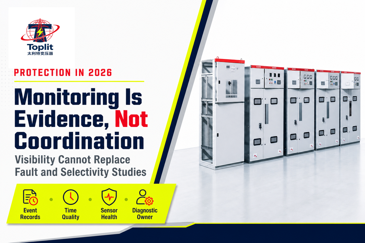
Monitoring in 2026 can improve event visibility, alarm context, and investigation speed, but it doesn’t establish fault level, zone boundaries, interrupting duty, or selectivity. Sensors and digital records become useful protection evidence only when their range, timestamp quality, threshold provenance, health status, access, and diagnostic ownership are controlled.
The Smart Electric Power Alliance grid-modernization discussion describes real-time monitoring, two-way communications, event data, and automated fault detection or isolation as modernization opportunities. That supports a visibility trend. It doesn’t support skipping a protection study or relaxing settings.
Connected monitoring also creates governance work. Assign data ownership, time synchronization, access control, credentials, software-update responsibility, retention, and incident response. Record sensor range, timestamp quality, calibration or health status, and the person who can classify an alarm. A patent or vendor feature proves that a method exists; it doesn’t prove field performance, ownership by Talite, or suitability for the reader’s project.
The 2026 action is practical: preserve event records in a form the protection engineer can correlate with released settings and drawings. Don’t treat a dashboard alarm as a diagnosis, and don’t let remote visibility hide an obsolete fault-current or topology assumption.
Key takeaway: Better monitoring shortens the path to a question. Coordination evidence is still required to answer whether the correct device will clear the correct zone.
Use a Setting Release Passport Before Energization
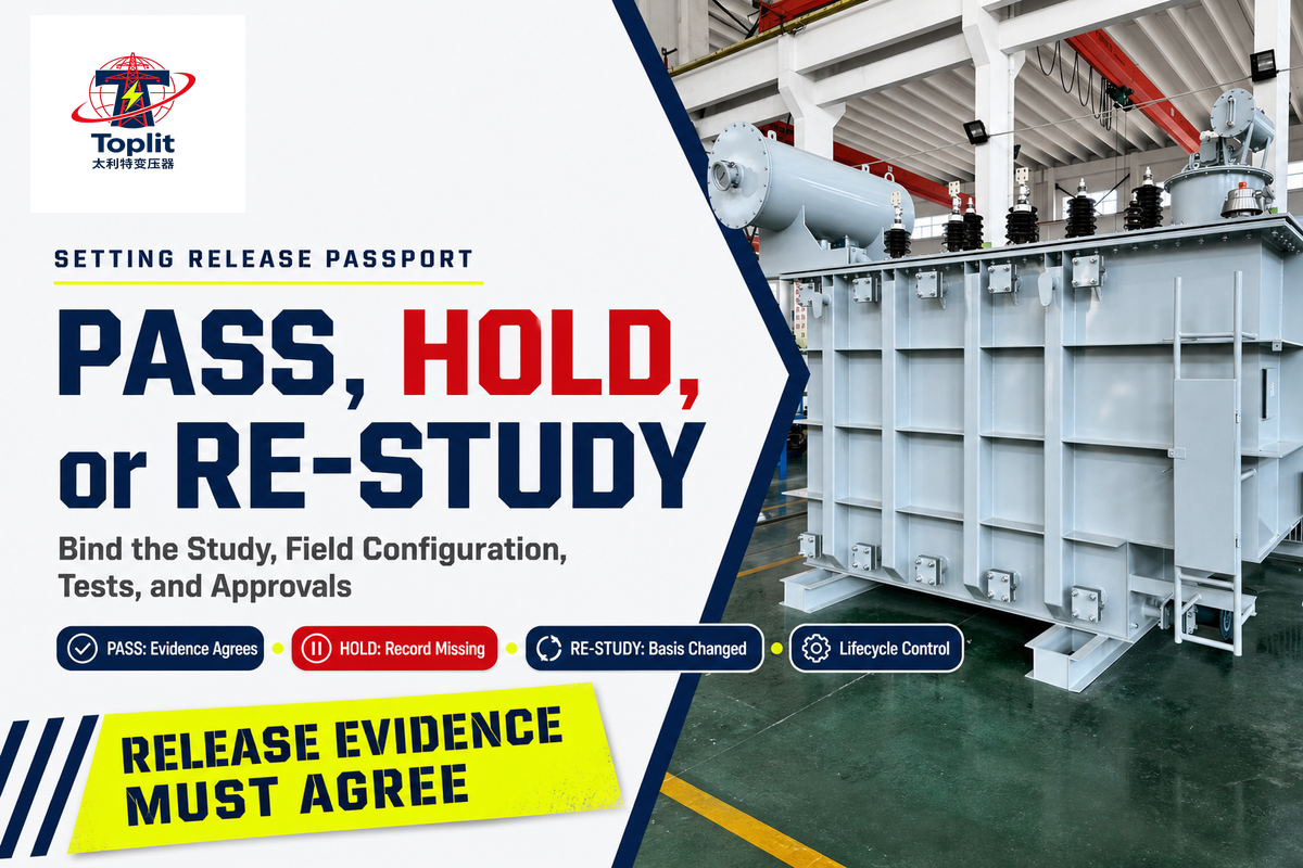
A setting release passport binds the approved study revision, device settings, field configuration, drawings, installation and in-service tests, approvers, and change history. It gives the owner three defensible outcomes: PASS when evidence agrees, HOLD when a required record is missing, and RE-STUDY when the system basis changed.
3-State Setting Release Passport
The 3-State Setting Release Passport connects study inputs, settings, field configuration, tests, approvals, and post-energization change triggers in one controlled record.
| Passport field | Evidence | PASS condition | HOLD / RE-STUDY trigger | Limitations / not suitable for |
|---|---|---|---|---|
| Study basis | Approved revision and input list | Matches released system | Missing input: HOLD; changed basis: RE-STUDY | A file name alone does not prove current approval. |
| Operating modes | Normal, alternate, islanded, reconfigured | All present modes assessed | New mode or source: RE-STUDY | Do not leave non-applicable modes blank. |
| Transformer data | Released drawings, nameplate basis, impedance | Matches installed unit | Unit or grounding change: RE-STUDY | Quotation revisions are not field verification. |
| Sensor configuration | CT/sensor data and wiring | Ratio, polarity, location, range verified | Sensor change or uncertainty: HOLD | Configured scaling cannot correct wrong field wiring. |
| Settings | Approved settings file and checksum | Device matches approved file | Mismatch: HOLD | A screenshot is weak configuration control. |
| Trip and interrupting path | Logic, trip supply, breaker/fuse record | End-to-end path verified | Untested path: HOLD | Relay output operation is not full clearing proof. |
| Installation tests | Signed test records | Scope and results accepted | Missing or failed test: HOLD | Bench tests do not replace site tests. |
| In-service verification | Measured magnitudes, angles, status, event record | Expected field behavior confirmed | Unexpected result: HOLD and investigate | An alarm count is not a diagnosis. |
| Approvals | Named utility, owner, engineer, commissioning approvals | Required signatures current | Unknown authority: HOLD | Approval roles vary by project and jurisdiction. |
| Lifecycle and change record | Owner, repository, review rule, change history | Triggers and evidence custody assigned | Material change: RE-STUDY or revalidate | No universal periodic interval is claimed. |
- Freeze the basis – identify the approved study, drawings, equipment, modes, and owners.
- Load the settings – verify that the field device matches the approved settings file.
- Test the path – check sensing, logic, trip supply, output, and interrupting-device operation.
- Review independently – compare design, wiring, settings, and test evidence with named responsibility.
- Issue the state – record PASS, HOLD, or RE-STUDY with approvers and open items.
- Control the lifecycle – preserve evidence and revalidate after a material change.
Suppose an inverter-based storage source is added after the original relay test. The relay may still pass its bench checks, but the source contribution, operating modes, reclosing behavior, and study assumptions have changed. The passport should issue RE-STUDY, name the study owner, and prevent the old settings from being treated as automatically current. After energization, the same logic applies to material grounding, transformer, sensor, firmware, relay, interrupting-device, or topology changes.
Post-energization work needs a maintenance owner, periodic-review authority, diagnostic owner, and evidence repository. Project and utility rules set the interval. The evidence responsibility matrix can structure ownership, but final responsibilities belong in the approved project record.
Key takeaway
A relay test answers whether a tested function operated. The Setting Release Passport answers whether the current system basis, field configuration, clearing path, approvals, and lifecycle evidence agree.
Frequently Asked Questions About Distribution Transformer Protection
Distribution transformer protection questions often look device-specific, but dependable answers require the protected zone, transformer construction, grounding, fault level, sensors, interrupting device, operating modes, and approval authority. The answers below define useful boundaries and deliberately avoid project settings.
What is the purpose of transformer protection?
Answer
Transformer protection detects abnormal conditions, identifies whether they belong to a protected zone, and initiates an approved response that limits equipment damage and supports personnel safety. A complete scheme also coordinates with adjacent devices, preserves required service where practical, verifies the trip path, and records what operated. Exact functions depend on transformer construction and the electrical system. Settings still need project fault levels, grounding, operating modes, equipment data, and approval.
What is the 80% rule for transformers?
Answer
“80% rule” can refer to different loading, continuous-load, or sizing practices. It is not a universal transformer protection setting. Identify the adopted code, equipment rating basis, load definition, ambient and cooling assumptions, utility criteria, and the question being answered. A phrase from a sizing discussion should never be copied into a fuse or relay setting without the project study. Ask the engineer to state the rule’s source, scope, calculation target, and release authority.
What is 64R protection?
Answer
64R is often used as a project or relay label for a restricted earth-fault function, but naming and implementation vary. Do not procure or approve a function from the label alone. Confirm the relay manual, protected winding, grounding path, phase and neutral current-transformer arrangement, operating characteristic, trip path, and the project drawing that defines the zone. The released function description should override shorthand used in emails or schedules.
What is the main protection of a distribution transformer?
Answer
There is no universal main protection for every distribution transformer. A small utility unit may rely on a different combination of external or integrated overcurrent interruption, surge protection, grounding, and construction-specific devices than a critical industrial transformer with dedicated relay functions. Size, construction, zone, criticality, grounding, and utility design determine the scheme.
Does a surge arrester protect a transformer from every overvoltage?
Answer
No. An arrester is one part of insulation coordination. Protection at the transformer depends on system grounding, arrester duty, protective level, physical separation, conductor route, bonding, grounding path, surge characteristics, and the transformer’s insulation basis. Other overvoltage mechanisms may need different analysis. Switching events, temporary overvoltages, and incoming-wave behavior do not collapse into one nameplate check. The released drawing should show the actual connection route, and field verification should compare that route with the installed conductors. Document who owns the insulation-coordination study, who verifies field routing, and which drawing revision controls the acceptance check. An arrester does not replace overcurrent, differential, thermal, or construction-specific protection. Verify the live standard and the project insulation-coordination basis before accepting the arrester arrangement.
Who approves transformer protection settings?
Answer
Approval depends on the serving utility, owner, authority having jurisdiction, project contract, and engineering responsibility. The release record should name the protection engineer, utility reviewer, owner representative, commissioning verifier, and final release authority. Transformer suppliers should not assume system-setting responsibility without network data.
Turn the protection question into an engineering-ready inquiry
Talite Transformer Co., Ltd. states that it has worked in the power-equipment sector for more than three decades and operates from the Hai’an Economic and Technological Development Zone in Nantong, Jiangsu. That company-provided background doesn’t replace project evidence, utility review, or settings approval.
Send the system one-line, operating modes, fault-current basis, transformer data, grounding, sensor and interrupting-device details, downstream curves, study ownership, and required approval records. Talite can review the transformer and quotation interfaces while qualified project parties retain protection-design responsibility.
Scope and evidence notice
This guide is educational engineering content, not a settings study, code opinion, utility approval, or compliance certificate. Original matrices are labeled synthesis from public evidence. Standards, utility requirements, equipment data, and site conditions must be verified for the current project.
Related Talite Resources
References & Sources
- IEEE C37.91-2021 public scope – IEEE Standards Association
- Understanding NFPA 70, National Electrical Code – National Fire Protection Association
- Arrester separation and lead-length presentation – CIGRE United States National Committee and American Electric Power
- IEEE C62.22-2009 status page – IEEE Standards Association
- Transformer protection is essential for reliable power – Consulting-Specifying Engineer
- Commissioning Testing Prevents Protection System Misoperations – North American Electric Reliability Corporation
- The Aging U.S. Power Grid: Navigating Toward Modernization – Smart Electric Power Alliance
![Pad-Mounted Transformer: How It Works [2026 Guide]](https://toplit-transformer.com/wp-content/uploads/2026/08/pad-mounted-transformer-guide-featured-150x150.png)
![Single Phase Pad Mounted Transformer Guide [2026]](https://toplit-transformer.com/wp-content/uploads/2026/08/single-phase-pad-mounted-transformer-guide-featured-1-150x150.png)