Get in touch with Talite Transformer Co., Ltd Company

How to Size a Transformer: kVA Formulas, Charts, and the Cost of Guessing High

This transformer kVA sizing guide is a five-step route from a load list to a nameplate rating: fix the load basis, run the single-phase or three-phase formula, convert the answer to amps, pick a standard size, then decide how much headroom the installation actually earns. Arithmetic is the easy part of that sequence. Estimating the load is where the error enters, and the error runs one direction.
In a 2006 T&D World account of its transformer-sizing programme, Southern Company compared metered demand against connected nameplate across a fleet that buys roughly 70,000 distribution transformers a year and reported the root cause plainly: “Frequently, the customer’s estimated demand, which is used to size the transformer, was significantly greater than the actual maximum demand.” Read the rest of this transformer sizing guide as an argument for measuring first and asking your supplier for real numbers second, not as an instruction to buy smaller. Updated August 2026.
What kVA Actually Measures, and Why Your Load Is Quoted in kW
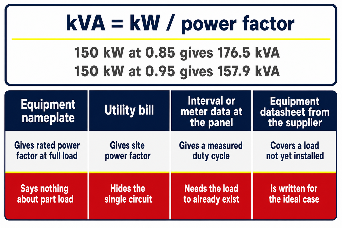
A transformer rated in kVA delivers kilowatts equal to its kVA rating multiplied by the load power factor, because kilovolt-amperes measure apparent power while kilowatts measure the real power the load consumes. Heating in the windings follows current, and current follows apparent power, so the nameplate is written in kVA.
kVA stands for kilovolt-ampere, one thousand volt-amperes of apparent power. Apparent power in an alternating current circuit is electric potential multiplied by current, before any account is taken of how the two waveforms line up in time. Real power is what remains once that phase relationship is applied, and ASHRAE Terminology defines electric power factor as that same ratio: real power in kilowatts over apparent power in kilovolt-amperes. Since AC power delivery charges the winding with the full current either way, the transformer is rated on the apparent figure and the load is quoted on the real one. Nameplates are printed in kVA rather than kW for that reason alone.
Conversion runs both directions and needs one number you have to supply: kVA = kW / power factor. A 150 kW load at a power factor of 0.85 needs 150 / 0.85 = 176.5 kVA of apparent power. Feed the same load in at 0.95 and the requirement drops to 157.9 kVA. That single input moves the answer by nearly 19 kVA, which is more than a full rung on the standard ladder at that size.
This guide publishes no table of typical power factors by load type, and the omission is deliberate. No authority in the 52-source evidence set for this article publishes one that survives checking, and an assumed power factor is exactly the input that quietly resizes the transformer. Four places carry a number you can defend instead.
| Source of the number | What it gives you | Where it falls short |
|---|---|---|
| Equipment nameplate | Rated power factor at full load for that one machine | Says nothing about part-load operation, where power factor usually falls |
| Utility bill | Site power factor, from billed kW against billed kVA demand | Whole-site average, so it hides the behaviour of the circuit you are transforming |
| Interval or meter data at the panel | Measured power factor across a real duty cycle | Requires the load to already exist, which rules it out for new build |
| Equipment datasheet from the supplier | Vendor-stated value for a load not yet installed | Written for the ideal case, so treat as an upper bound and ask for the test basis |
Boundary condition: for a load that’s mostly resistive, heating and lighting for example, power factor sits close to unity and the kW and kVA figures converge. Motor-heavy and electronics-heavy circuits are where the conversion decides the rating.
How many kW can a 50 kVA transformer handle?
A 50 kVA transformer supplies 50 kW only into a load at unity power factor. At 0.9 it supplies 45 kW, at 0.85 it supplies 42.5 kW, and at 0.8 it supplies 40 kW. Nothing about the transformer changes across those four cases. Apparent power is the constant the winding is designed around, and real power is what the load extracts from it.
Working the other way, a 50 kVA unit at 240 V single-phase carries 208 A of secondary current at any of those power factors, which is why protection and conductors are sized from the kVA rating rather than from the kW the load happens to draw. Transformers are rated in kVA because the winding never sees the power factor, only the load amperage that flows through it.
Step 1: The Four Numbers to Fix Before You Touch a Formula
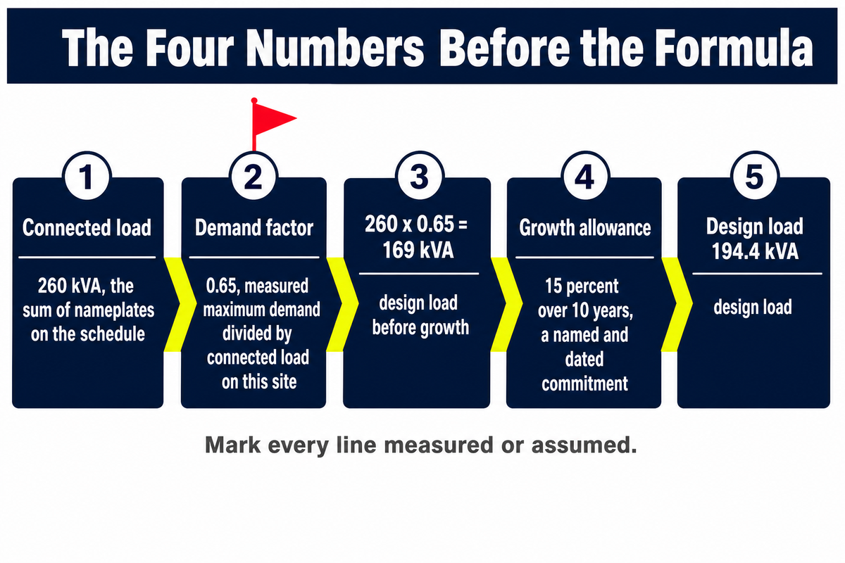
Four inputs decide the transformer kVA rating before any formula runs: connected load, the demand factor that converts it to actual maximum demand, a growth allowance with a stated horizon, and the voltage and phase pair on both sides. Get the second one from measurement, not from habit.
Two independent bodies define the term the same way. California Code of Regulations Title 8, Section 2300, states that demand factor is “the ratio of the maximum demand of a system, or part of a system, to the total connected load of the system or part under consideration,” and separately defines a continuous load as one “where the maximum current is expected to continue for three hours or more.” ASHRAE Terminology gives the same ratio and adds load factor: kilowatt hours divided by demand in kilowatts times the hours in the period, which is the same thing as average load divided by peak load.
| Line | Value | Where it comes from |
|---|---|---|
| Connected load | 260 kVA | Sum of nameplates on the schedule |
| Demand factor | 0.65 | Measured maximum demand divided by connected load on this site, not a generic figure |
| Design load before growth | 169 kVA | 260 x 0.65 |
| Growth allowance | 15 percent over 10 years | A named, dated commitment, not a habit |
| Design load | 194.4 kVA | 169 x 1.15 |
Accurate sizing depends on which of these five lines was measured and which was assumed, and the correct kVA rating follows from the demand factor far more sensitively than from the arithmetic. Note what the 0.65 is doing. The ranking pages reviewed for this article all start at the formula and treat connected load as though it were demand, which is the mistake Southern Company’s 2006 study found in its own estimating practice. Their fix was to rebuild sizing around metered demand per building type and 8,760-hour load data, and the result was “one to two transformer sizes smaller than what was generally specified in the past.”
Measured demand is the starting number, not the finishing one. Published diversity measurements on real office equipment scatter widely between building types, and again between lighting and receptacle circuits. This guide quotes no percentage band for them, because the bands in circulation could not be traced to a source that survives checking, and a spread nobody can pin down is exactly the input you have to measure rather than borrow. Measured peak demand also says nothing about the current waveform behind it, which is the subject of the exceptions section further down.
One term to handle with care: diversity factor. Two current professional sources use it in reciprocal senses, one as a number at or above 1, the other as a derating applied to connected load. State the ratio in words before you use it, or the arithmetic inverts silently. The load basis itself is normally settled upstream, during distribution system design, which is where these four numbers should already be written down.
Step 2: The Single-Phase and Three-Phase kVA Formulas
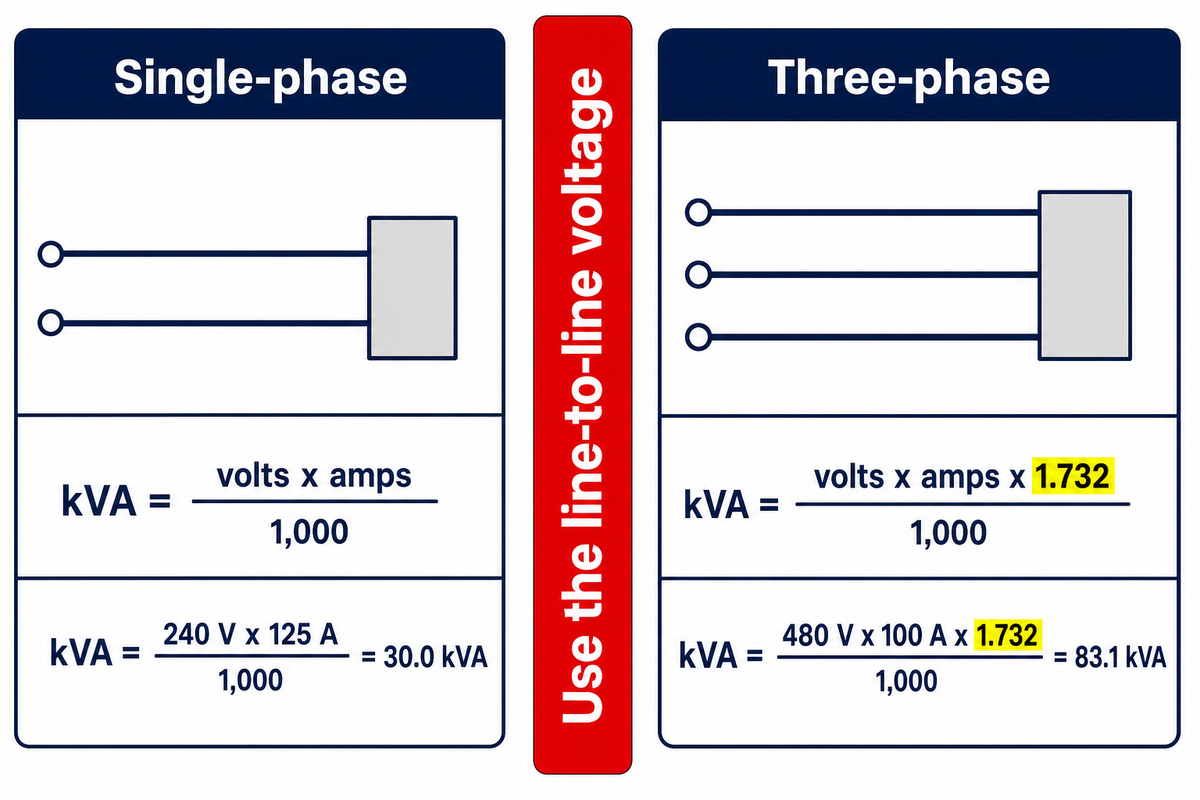
Single-phase sizing uses kVA = volts x amps / 1,000. Three-phase sizing uses kVA = volts x amps x 1.732 / 1,000, where 1.732 is the square root of 3 and accounts for the 120-degree phase relationship between the three line currents. Carry units through every line of the substitution.
With the load basis settled and those four numbers written down, the arithmetic is the mechanical part of the job.
Single-phase worked example. A 240 V single-phase load drawing 125 A gives kVA = 240 x 125 / 1,000 = 30.0 kVA. Standard single-phase liquid-immersed ratings run 25 kVA then 37.5 kVA, with nothing between, so a calculated 30.0 kVA lands 20 percent above one rung and 20 percent below the next. A single-phase transformer for this load therefore comes off a list that has nothing between those two rungs. Hold that number, because Step 4 is about what to do with it.
Three-phase worked example. A 480 V three-phase machine drawing 100 A gives kVA = 480 x 100 x 1.732 / 1,000 = 83.1 kVA. Standard three-phase ratings offer 75 kVA or 112.5 kVA. Picking the lower rung leaves the machine 10 percent short of its stated draw; picking the higher one buys 35 percent more transformer than the calculation asked for.
Why the two formulas differ comes down to how the electrical load is fed. Single-phase electric power arrives through one pair of conductors, so apparent power is load voltage multiplied by electric current and nothing else. Three-phase electric power splits the same duty across three conductors whose currents peak at different instants, and 1.732 is what accounts for that offset. Single-phase kVA and three-phase kVA come from the same two measurements, and only the 1.732 separates them. Applying the wrong one moves the answer by the full 1.732: the single-phase formula used on a three-phase load understates required kVA by 42 percent, and the three-phase formula used on a single-phase load overstates it by 73 percent. Either error is larger than any headroom argument in this guide.
📐 Engineering Note
Substituting the line-to-neutral voltage for the line-to-line voltage is the most common arithmetic failure on a 480Y/277 V system. Using 277 in place of 480 undersizes the result by a factor of 1.732. Carrying the units through each line makes the slip produce a visibly wrong answer instead of a plausible one, which is the only reason the habit is worth the extra keystrokes.
Readers who want the arithmetic done for them can run the same inputs through the transformer sizing calculator. Any transformer kVA calculator runs exactly these two lines, so the answer is decided by the inputs rather than by the tool that multiplies them. Boundary condition: both formulas assume balanced load. Badly unbalanced single-phase loading on a three-phase bank is sized on the worst phase, not on the total divided by three.
How do you calculate kVA for a transformer?
Start from the current and voltage the load actually presents, not from the nameplate of the equipment feeding it. For single-phase, multiply volts by amps and divide by 1,000. For three-phase, multiply volts by amps by 1.732 and divide by 1,000. If the load schedule is in kilowatts rather than amps, convert first with kVA = kW / power factor, then check the result against the amps figure the transformer will have to carry.
Two rules keep the calculation honest: use the line-to-line voltage on three-phase systems, and record which figure was measured and which was estimated. Both rules matter because you calculate transformer capacity once and then live with the answer for decades. A calculated kVA built on three estimates and one measurement is a different quality of number from one built on four measurements, even though both print to one decimal place. Where two sources disagree, calculate the kVA rating from each of them and buy against the measured one.
Step 3: Convert kVA to Amps and Check What the Current Does
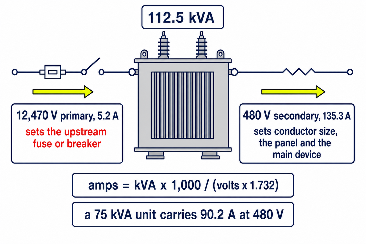
Full-load current for a three-phase transformer equals kVA x 1,000 / (volts x 1.732). A 112.5 kVA unit at 480 V carries 135.3 A on the secondary; the same unit fed from a 12,470 V primary carries only 5.2 A on the primary. Both figures decide equipment that costs more than the transformer.
Sizing usually stops at the kVA number, and that’s where the money leaks. Many transformer calculator pages stop there too, and a kVA calculator that returns a single rating leaves the amps question open. Secondary amperage sets electrical conductor size, the panel, and the main device. Primary amperage sets the fuse or breaker upstream and, as the breaker and fuse section shows, drops into a different row of the code table below 9 A. Voltage and amperage therefore get read on both sides of the unit: the input voltage on the primary side fixes one current, and the secondary winding carries the other. Every figure in the table below is computed from the formula above rather than copied from a chart.
| kVA rating | 208 V | 240 V | 480 V | 600 V |
|---|---|---|---|---|
| 15 | 41.6 A | 36.1 A | 18.0 A | 14.4 A |
| 30 | 83.3 A | 72.2 A | 36.1 A | 28.9 A |
| 45 | 124.9 A | 108.3 A | 54.1 A | 43.3 A |
| 75 | 208.2 A | 180.4 A | 90.2 A | 72.2 A |
| 112.5 | 312.3 A | 270.6 A | 135.3 A | 108.3 A |
| 150 | 416.4 A | 360.9 A | 180.4 A | 144.3 A |
| 225 | 624.6 A | 541.3 A | 270.6 A | 216.5 A |
| 300 | 832.7 A | 721.7 A | 360.9 A | 288.7 A |
| 500 | 1,387.9 A | 1,202.9 A | 601.4 A | 481.1 A |
| 750 | 2,081.9 A | 1,804.3 A | 902.1 A | 721.7 A |
| 1000 | 2,775.8 A | 2,405.7 A | 1,202.9 A | 962.3 A |
Reading the table for the 83.1 kVA three-phase load from Step 2: at 480 V, the 75 kVA rung carries 90.2 A and the 112.5 kVA rung carries 135.3 A. Rounding up one rung raises the secondary current rating by 45 A, which is a conductor and switchgear decision as much as a transformer decision. For voltages outside this table, use the full-load current calculator. Boundary condition: these are full-load figures at rated voltage, so they’re a sizing basis for conductors and devices, not a prediction of operating current.
Step 4: Standard Transformer Sizes and the kVA Rounding Window
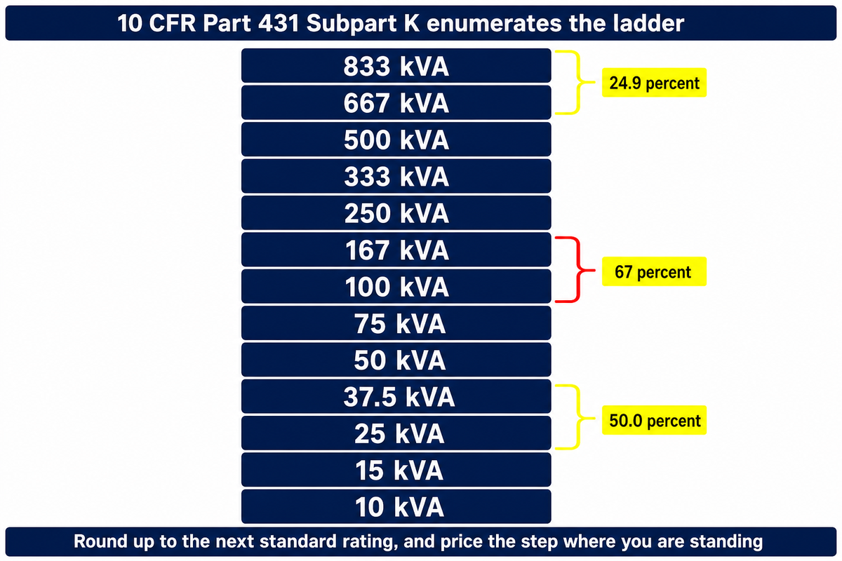
Standard transformer sizes aren’t a manufacturer convention; federal efficiency law enumerates the kVA ladder rung by rung. The transformer sizing charts circulating on this query mostly reproduce that ladder, usually reprinted without the citation. Because the gaps between rungs are uneven, the free headroom you get by rounding up ranges from 25 percent to 67 percent depending on where your calculated number lands. Call that gap the kVA Rounding Window.
Competitor guides on this query source their ratings ladder to a trade magazine, and one of them mixes a single-phase rating into a three-phase series. There is a better source, and it is free to open. 10 CFR Part 431 Subpart K tabulates minimum efficiency rating by rating, which enumerates the ladder, and Section 431.192 defines a “basic model” partly by “the same standard kVA rating.” Rounding up is therefore a regulatory artefact, not merely a habit of the catalogue: when a calculation lands between rungs, you round up to the next standard rating in that table. The regulation itself covers the in-between case, directing that ratings “not appearing in the table shall have their minimum efficiency level determined by linear interpolation,” which is an efficiency rule for an off-ladder rating rather than a licence to order a size no catalogue stocks. A required kVA almost never coincides with a rung, so the minimum kVA you can actually buy is the next available standard rating above the calculation.
| Rating | Next rung up | Rounding window | Minimum efficiency at 50 percent load |
|---|---|---|---|
| 10 kVA | 15 kVA | 50.0 percent | 98.70 percent |
| 15 kVA | 25 kVA | 66.7 percent | 98.82 percent |
| 25 kVA | 37.5 kVA | 50.0 percent | 98.95 percent |
| 37.5 kVA | 50 kVA | 33.3 percent | 99.05 percent |
| 50 kVA | 75 kVA | 50.0 percent | 99.11 percent |
| 75 kVA | 100 kVA | 33.3 percent | 99.19 percent |
| 100 kVA | 167 kVA | 67.0 percent | 99.25 percent |
| 167 kVA | 250 kVA | 49.7 percent | 99.33 percent |
| 250 kVA | 333 kVA | 33.2 percent | 99.39 percent |
| 333 kVA | 500 kVA | 50.2 percent | 99.43 percent |
| 500 kVA | 667 kVA | 33.4 percent | 99.49 percent |
| 667 kVA | 833 kVA | 24.9 percent | 99.52 percent |
| 833 kVA | Top of this table | Not applicable | 99.55 percent |
Rounding window is the gap to the next rung expressed as a percentage of the rung you’re standing on, and it varies by a factor of nearly three across the ladder. At 100 kVA the next size up hands you 67 percent more capacity. At 667 kVA it hands you 24.9 percent. Same decision, very different purchase, which is why one step of kVA size has to be priced where you’re standing rather than in general. Three-phase units have their own tables in the same rule: Table 6 runs 15, 30, 45, 75, 112.5, 150, 225, 300, 500, 750, 1,000, 1,500, 2,000, 2,500, 3,750 and 5,000 kVA, and two of those rungs matter later in this guide: 300 kVA and 500 kVA. The 1,000 kVA rung near the top of that table is specified in full on the 1000 kVA 11 kV cast resin transformer page, which is what a rating on this ladder looks like once it is quoted rather than calculated. Full ratings context sits on the distribution transformer ratings page.
Boundary condition: the efficiency column is a legal minimum at one reference load, not the efficiency of any specific unit at your loading. Liquid-immersed efficiency is stated at 50 percent of nameplate, low-voltage dry-type at 35 percent, so the two columns aren’t directly comparable across construction types.
Step 5: How Much Headroom, and the Three-Question Headroom Rule
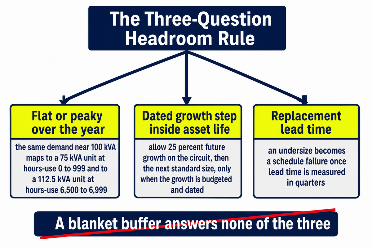
Headroom answers three questions, not one: is the load flat or peaky over the year, is there a dated growth step inside the asset life, and how long would a replacement take to arrive. A blanket 20 to 25 percent buffer answers none of them, and the same metered peak can justify two different ratings.
Evidence for the first question is unusually concrete. Southern Company’s published 2006 sizing table crosses 22 demand bands with 14 hours-use bands, where hours-use is annual kWh divided by maximum kW demand. In their table a demand near 100 kVA maps to a 75 kVA unit at hours-use 0 to 999, and to a 112.5 kVA unit at hours-use 6,500 to 6,999. Identical peak, one size apart, purely from the shape of the year. Their published wording is direct: “Loads with a very high demand but a very low hours-use number may be served more effectively with a smaller transformer than loads of the same kVA demand with higher hours-use loads.”
| If this is true of your load | What it does to the answer | Where the row stops applying |
|---|---|---|
| Flat profile, high hours-use above 6,000 | Utility practice moves up one rung at the same metered peak | Not if the recorded peak was a one-off commissioning event |
| Peaky profile, hours-use below 1,000 | Same peak can be served one rung lower | Not if several peaks coincide or motor starts overlap |
| Motor-heavy load | Size on starting kVA, since running current understates the demand at pick-up | Soft starters and drives change the starting profile, so use the drive data |
| Dated growth step inside asset life | Professional convention allows 25 percent growth on the circuit, then the next standard size | Not if the growth is speculative rather than budgeted and dated |
| Non-linear load present | Nameplate kVA is not usable capacity; capability must be calculated | Negligible where measured distortion is low, so measure before assuming |
| Replacement lead time measured in quarters | An undersize becomes a schedule failure, so widen only after the rows above are answered | Not if a spare or a loaner unit is already held |
| Oil-filled unit expected to sit very lightly loaded | Oversizing carries its own failure mechanism, so do not treat headroom as free | Reported as an oil-filled behaviour, explicitly not a dry-type one |
Row four repeats the actual professional convention rather than a straw man: engineering guidance for nonresidential buildings recommends allowing 25 percent future growth on the circuit and then adopting the next standard transformer size up. Nothing is wrong with that rule when the growth is real and dated. The argument here is with applying it when neither condition holds. Sizing your transformer around an undated growth step is how the right transformer on paper becomes the wrong one on site.
Row seven comes from field practice rather than from a standard. Practitioners managing oil-filled fleets report that a unit loaded far below its rating never brings the oil to operating temperature, so the oil doesn’t circulate and moisture stratifies, with a rough working threshold of sustained loading below 10 to 25 percent. Engineers describing that mechanism are explicit that it doesn’t apply to dry-type units.
RFQ checklist, copy these eight lines into your quote request:
| Parameter | What to state | Why it matters | How to verify |
|---|---|---|---|
| Measured maximum demand | kVA and the metering window it came from | Estimated demand ran systematically high in a 70,000-unit-per-year utility fleet study | Utility interval data or a metered log, dated |
| Hours-use | Annual kWh divided by maximum kW demand | Moves the recommended rating by one rung at identical peak | Twelve months of billing data |
| Demand factor basis | Maximum demand divided by total connected load | Defined in Title 8 Section 2300 and in ASHRAE Terminology the same way | Show both numerator and denominator, not the ratio alone |
| Harmonic content | Measured distortion, and K-rating if specified | Capability under nonsinusoidal current must be calculated, not read off the nameplate | Power quality survey; capability method per IEEE C57.110 |
| Tested no-load loss | kW at 100 percent rated voltage | Weighted four times as heavily as load loss in at least one public utility bid evaluation | Factory test report; ask in writing which loss tolerance the quotation is built on |
| Tested load loss | kW at rated load | Scales with the square of loading, so it dominates on heavily loaded units | Factory test report; have the total-loss tolerance stated on the quotation |
| Efficiency basis | Reference load used for the quoted efficiency | Liquid-immersed is stated at 50 percent load, low-voltage dry-type at 35 percent | 10 CFR 431.196 tables, quoted by rating |
| Regulatory scope | Whether the unit is a covered distribution transformer | Thirteen classes are excluded outright, and exclusion changes what the quote must prove | 10 CFR 431.192 definitions, checked class by class |
What is the 80 percent rule for transformers?
Nothing in transformer loading is governed by an 80 percent rule; the figure comes from overcurrent device sizing and gets transplanted. Continuous loads are defined as those where maximum current continues for three hours or more, and protective devices are sized against that duty, which is where 80 percent and its reciprocal, 125 percent, come from. Transformer loading is governed by temperature and time instead.
The industry loading guide for mineral-oil-immersed units treats loading above nameplate as a thermal calculation involving hotspot temperature, insulation aging and cooling class, not as a fixed percentage. Rated capacity in that framework is a thermal statement about the winding rather than a percentage budget to spend down. Practical consequence: a transformer running at 90 percent of nameplate on a flat load isn’t violating anything, while the same unit at 70 percent with severe harmonic distortion may already be overheating. Use the 80 percent figure where it belongs, on the device, and size the transformer on measured demand plus the waveform.
The 8,760-Hour Oversize Penalty: What Guessing High Actually Costs
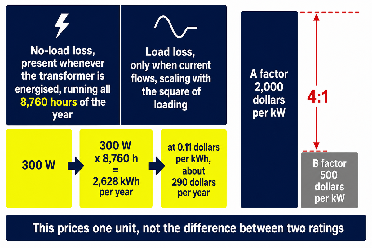
No-load loss runs for all 8,760 hours of the year whether the load appears or not, which is why buyers weight it far more heavily than load loss when they evaluate bids. Because tested loss values aren’t published per rating, the only honest way to price one rating step is to ask both suppliers for their numbers.
Start with the mechanism, because it needs no figures at all. Core loss is present whenever the transformer is energised. Winding loss appears only when current flows, and scales with the square of loading. Buy a unit for a load that never arrives and it still pays the first bill every hour of every year of its service life.
Practitioners price that mechanism with straightforward arithmetic. The worked example below comes from an engineering discussion forum rather than from a test report, and it is used here for its method rather than its authority. Take a 75 kVA unit at roughly 1.3 percent total loss at full load, of which about 0.5 percent is fixed. Fixed loss is then 75,000 x 0.005 = 375 W on paper, while the practitioner working that example put the real figure nearer 300 W; the arithmetic below deliberately uses the lower of the two. At 300 W: 300 W x 8,760 h = 2,628 kWh per year, and at 0.11 dollars per kWh that’s about 290 dollars per year, burned whether or not the load ever arrives. Note carefully what that calculation is and isn’t. It prices the core loss of one unit. It doesn’t price the difference between two adjacent ratings, and this guide won’t pretend otherwise.
Buyers who purchase these units in volume put a price on the asymmetry directly. A published municipal utility padmount transformer specification evaluates competing bids by adding 2,000 dollars per kW of no-load loss and 500 dollars per kW of load loss to the offered price, a four-to-one weighting in favour of core loss reduction. Post-award, the same document applies penalties at those rates and credits at half of them. Read that as how buyers weight the two loss types, not as a cost delta between ratings.
Total owning cost, with the loss weightings a real utility publishes:
| Term | What it is | Published value in that bid evaluation |
|---|---|---|
| Purchase price | Offered price for the unit | From the quote, per supplier |
| A factor | Capitalised value of one kW of no-load loss | 2,000 dollars per kW |
| B factor | Capitalised value of one kW of load loss | 500 dollars per kW |
| Post-award penalty | Charged where tested loss exceeds the guarantee | Same rates, applied against the supplier |
| No-load loss definition | Excitation or core loss | Measured at 100 percent rated voltage |
Four numbers to demand on the quote, for each of the two units you are comparing: tested no-load loss in kW, tested load loss in kW, price, and the loading profile the supplier assumed. With those four, the formula above returns an evaluated cost per unit and the comparison becomes arithmetic. Without them, any published watt-level difference between two ratings is guesswork, because the federal efficiency rule states a single percentage at one reference load and one point cannot be separated into its two loss components.
One first-party curiosity closes the section, and it needs no watt figures at all. The federal minimum efficiency ladder is not monotonic in kVA. Table 6 to paragraph (b)(3), which applies to non-submersible liquid-immersed units manufactured on or after 23 April 2029, requires 99.42 percent at 300 kVA but 99.38 percent at 500 kVA, and slips again above 2,500 kVA. Submersible units keep the earlier table. Going one size up can land on a lower mandated efficiency floor. Whether a given unit is covered at all is worth checking with the DOE scope checker, and the bid arithmetic above can be run in the loss capitalisation evaluator.
Second penalty, rarely mentioned: a larger transformer has lower impedance and raises available fault current on the secondary. That can push the required interrupting rating of the downstream switchgear, which is a cost that doesn’t appear anywhere on the transformer quotation.
Sizing the Breaker and the Fuse Around the Transformer
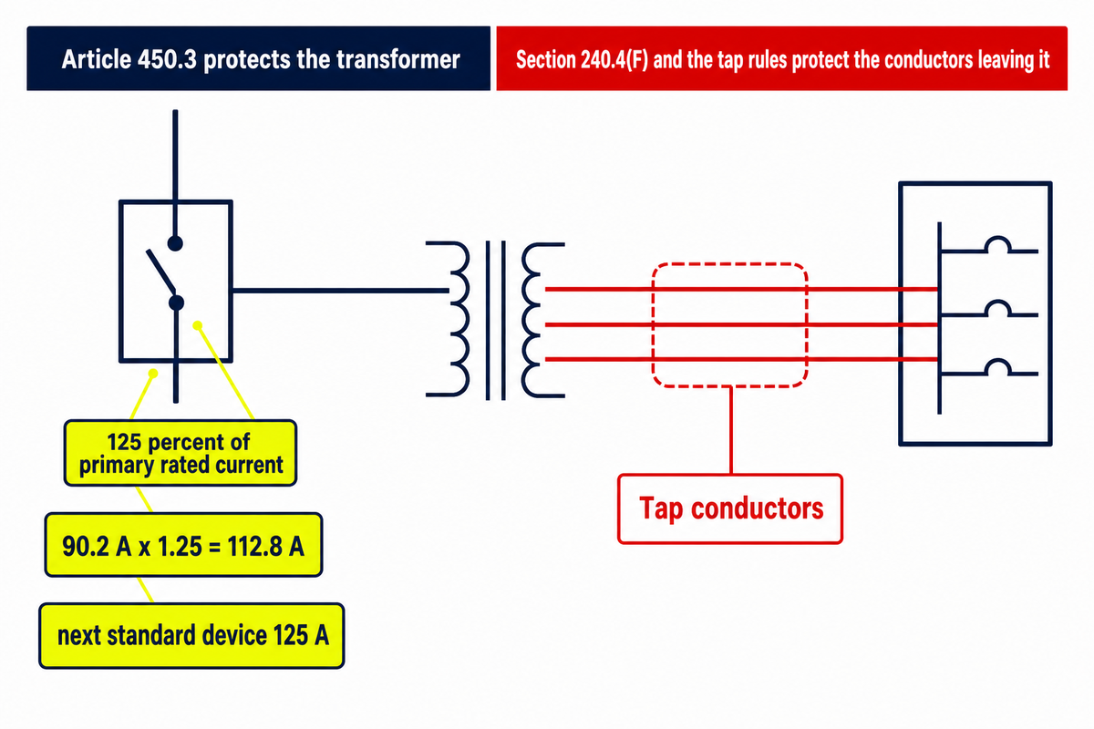
For transformers rated 1,000 V and less, primary-only overcurrent protection is permitted at 125 percent of primary rated current where that current is 9 A or more, and 250 percent on the primary where secondary protection at 125 percent is also provided. Satisfying that table protects the transformer, not the conductors leaving it.
NFPA 70, the National Electrical Code, Article 450.3, in the 2017 edition reproduced by the International Code Council, splits into two tables: Table 450.3(A) for transformers over 1,000 V and Table 450.3(B) for 1,000 V and less. Table 450.3(B) also carries rows for primary currents below 9 A, which this guide deliberately doesn’t reproduce, because those rows weren’t verified against the code text during research for this article. Read them from the code itself rather than from any summary, this one included.
Worked example, carried straight from the amps table above. A 75 kVA transformer on a 480 V primary draws 90.2 A. Multiply by 125 percent: 90.2 x 1.25 = 112.8 A. The New York City filing discussed below states 112.9 A for the same transformer, which is the same calculation carried with the square root of 3 written as 1.73 rather than 1.732. Either figure lands between standard device ratings, and Note 1 to the table permits the next higher standard rating, giving 125 A as the maximum primary-only device.
Here’s where the table stops being the whole story. That exact arrangement, 75 kVA protected by a 125 A primary breaker, went to the New York City Department of Buildings Electrical Code Revision and Interpretation Committee in 2016. The contractor’s arithmetic was correct. The installation was still rejected. Committee answer, verbatim:
“No. The primary protection only protects the transformer’s secondary side only. Your OCPDs are not located at the source of power so the secondary conductor is not protected as required by subsection 240.4(F). Your transformer secondary conductors are indeed tap conductors and you must comply with the tap rules.”
Article 450 protects the transformer. Section 240.4(F) and the tap rules protect the conductors leaving it, and satisfying the first doesn’t discharge the second. Boundary condition on this entire section: percentages quoted here describe the published rule, and the final decision on any specific installation belongs to the authority having jurisdiction, which is exactly what the New York record demonstrates.
When the Standard Method Does Not Apply
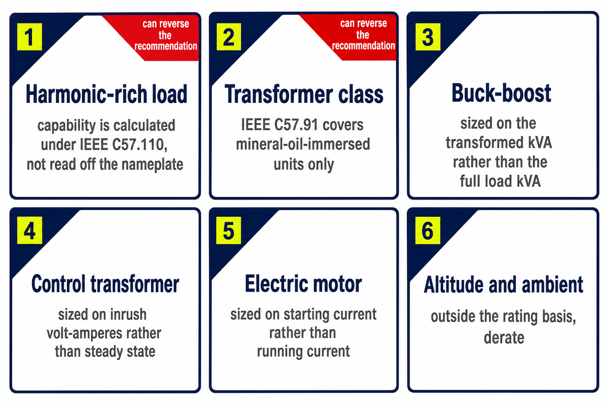
Six situations break the method above, and two of them can reverse its recommendation outright: harmonic-rich load, where a transformer overheats below nameplate, and transformer class, where the guide or the regulation you’re quoting doesn’t cover the unit in front of you. Check both before trusting a metered peak.
1. Harmonics, and why a metered peak isn’t the finishing number. Under nonsinusoidal load current, capability is something you calculate, not something you read off a nameplate. IEEE C57.110-2018 exists for this problem, giving methods for conservatively evaluating whether an existing installed dry-type or liquid-immersed transformer can supply nonsinusoidal load currents as part of the total load, and for specifying a new one that will. Its 1986 edition stated the purpose as determining that capability “without loss of normal life expectancy,” which names the cost of getting it wrong. Non-linear load calls for a K-rated or harmonic-rated unit and a distortion measurement, not a larger number picked from the ladder.
2. Transformer class is a scope boundary, not a footnote. IEEE C57.91 is the loading guide people quote when they talk about running a transformer above nameplate, and its scope is mineral-oil-immersed distribution and power transformers and step-voltage regulators. Dry-type, drive-isolation, rectifier and welding units are outside it. Worth stating plainly, since the guide is frequently cited as though it granted free capacity: the current 2025 edition covers estimating the effects of loading above nameplate including damage to insulation, gas generation and loss of life. Insulation spent that way is a slow route to transformer failure rather than a sudden one. Spending insulation life deliberately is a legitimate engineering decision. Confusing it with “you never needed the bigger unit” isn’t.
3 to 6, the four that stay short. Buck-boost units are sized on the transformed kVA rather than the full load kVA. Control transformers are sized on inrush volt-amperes rather than steady state, which is why a control transformer picked from running load leaves the contactor chattering on pick-up. An electric motor is sized on its starting current rather than its running current. Altitude and ambient conditions outside the rating basis call for derating.
Scope is also a legal question, and the regulation answers it by name. Section 431.192 defines a covered distribution transformer as one with input at or below 34.5 kV, output at or below 600 V, at 60 Hz, rated 10 to 5,000 kVA liquid-immersed or 15 to 5,000 kVA dry-type, and it excludes thirteen classes outright. Those thresholds are United States law: a project specified to IEC practice in another market works from a different ratings ladder and a different efficiency class, so confirm which regime governs the purchase before borrowing any number from this section.
| Excluded class | What changes when your unit is one of these |
|---|---|
| Autotransformer | Buck-boost units fall here; size on transformed kVA, not load kVA |
| Drive (isolation) transformer | Drive duty implies harmonic content; capability is calculated, not assumed |
| Grounding transformer | Rated for fault duty and duration rather than continuous load |
| Machine-tool (control) transformer | Size on inrush volt-amperes at pick-up, not steady-state burden |
| Nonventilated transformer | Cooling class differs, so loading margin cannot be borrowed from ventilated data |
| Rectifier transformer | Explicitly outside IEEE C57.110 as well; use the rectifier-specific basis |
| Regulating transformer | Duty is voltage correction, so kVA is not the primary selection variable |
| Sealed transformer | Enclosure changes the thermal path and the loading envelope |
| Special-impedance transformer | Impedance is specified for fault-current reasons, which interacts with switchgear ratings |
| Testing transformer | Intermittent duty, so continuous-rating arithmetic does not transfer |
| Tap range of 20 percent or more | Wide tap range shifts the rated-voltage basis your amps calculation assumed |
| Uninterruptible power supply transformer | Load is electronic and non-linear by construction |
| Welding transformer | Duty cycle governs, so a continuous kVA figure misstates the requirement |
Configuration matters here too. A pole-mounted unit on a single-phase service is one of the arrangements where three-phase arithmetic simply doesn’t apply, and a dry-type transformer sits outside the loading guide most sizing articles quote. Check which document actually governs your unit before borrowing a rule from it.
What Lead Times Have Changed About Sizing Decisions

Procurement conditions have turned an undersized order from a purchasing problem into a schedule problem, which raises the value of getting the load basis right rather than the value of buying margin. Ordering earlier locks the rating in before the design is settled, so oversizing isn’t a free hedge.
Once the governing document is settled, the remaining constraint on the unit is delivery rather than arithmetic.
Demand is the part of this story that’s measured rather than asserted. Wood Mackenzie data, reported in January 2026 by POWER Magazine, put distribution transformer demand up 34 percent since 2019 and power transformer demand up 119 percent over the same period. On price, a Congressional Research Service report, R48933, cites Bureau of Labor Statistics producer price indices showing both distribution and large power transformers up roughly 40 percent from 2020 to 2024 in inflation-adjusted terms.
Those two price statements aren’t the same measurement and shouldn’t be stacked. The federal series is inflation-adjusted from a 2020 base; the analyst series that circulates alongside it is nominal from a 2019 base, which is why its percentages look larger. Every figure in this section carries its own as-of date for the same reason: procurement conditions in this market have moved fast enough that an undated percentage isn’t worth quoting.
Lead times need one correction that circulates constantly and is wrong for this audience. The multi-year figures quoted in most shortage coverage, well past the two-year mark, belong to power transformers and generator step-up units, and this guide sizes distribution transformers. The number in circulation for the three-phase padmount units data centres buy comes from a 2025 post by an equipment distributor rather than from an independent survey: roughly 40 weeks or more, against 8 to 12 weeks before 2020. Read it as a trade datapoint rather than a measured lead-time index. Dissent belongs on the record too: a broker quoted in the same POWER feature says there’s no shortage and calls it exaggerated to drive pricing, a claim the publication itself notes is difficult to validate. Installed-base counts also disagree. One dealer account, citing an NREL page, puts 60 to 80 million distribution transformers in service; the POWER feature above counts roughly 40 million units already past their expected service life, which is more than half the fleet rather than the whole of it. No single count is quoted here as settled, and neither should yours be without a name attached to it.
One dated item to watch rather than to act on: the 2029 efficiency tier is codified law today, and a June 2026 Department of Energy request for information, docket EERE-2026-BT-STD-0133, asks how those standards interact with domestic manufacturing capacity and material cost. Comments closed 15 July 2026 with 35 received. An open proceeding isn’t a repeal, and specifications written this year should still be written against the rule as it stands.
The decision this section actually changesLong lead times argue for finishing the load basis earlier, not for adding kVA. An order placed before the design settles fixes rating, impedance and phasing while the information is at its thinnest, which is the opposite of what a schedule risk should buy you.
Sizing a transformer correctly ends with numbers somebody has tested, not with numbers somebody has assumed. Talite Transformer Co., Ltd. has worked in the power equipment sector for more than three decades, operating as a research, production and sales enterprise from the Hai’an Economic and Technological Development Zone in Nantong, Jiangsu Province. Bring the eight RFQ lines above, then request a project-specific transformer review, or request a written quotation with your measured demand attached.
Transformer kVA Sizing: Frequently Asked Questions
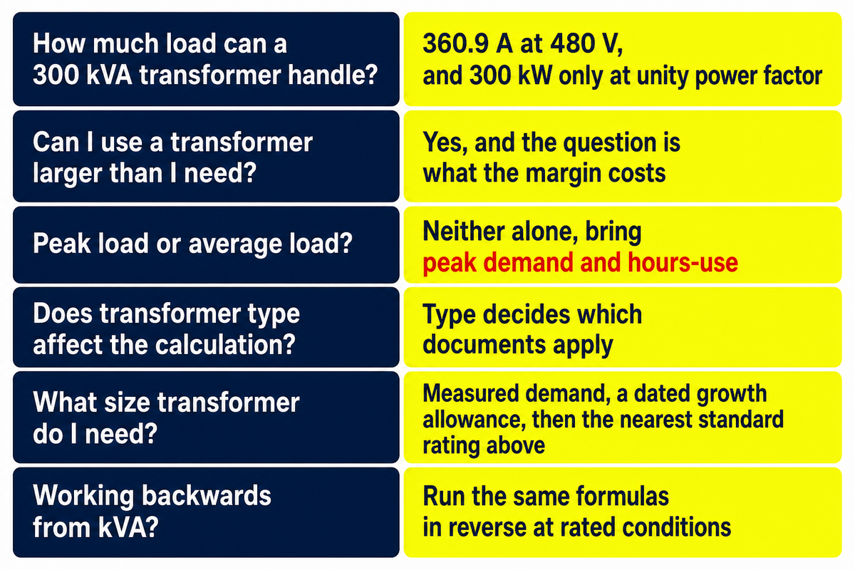
How much load can a 300 kVA transformer handle?
A 300 kVA three-phase transformer carries 360.9 A of full-load secondary current at 480 V, or 832.7 A at 208 V, from kVA x 1,000 / (volts x 1.732). In real power it supplies 300 kW only at unity power factor, 270 kW at 0.9 and 255 kW at 0.85. Whether it can carry that continuously depends on ambient conditions, cooling class and the harmonic content of the current, none of which appear in the arithmetic above.
Can I use a transformer that is larger than I need?
Yes, and the question is what the margin costs rather than whether it’s permitted. Three costs recur. Core loss runs for all 8,760 hours regardless of load, and at least one published utility bid evaluation weights it four times as heavily as load loss for that reason. Lower impedance on a bigger unit raises available fault current, which can drive the interrupting rating of downstream switchgear. Oil-filled units expected to sit very lightly loaded have a reported failure mechanism of their own, where the oil never reaches operating temperature and moisture stratifies. One practitioner account posted to an engineering forum describes a badly oversized installation dragging site power factor down far enough that replacement paid for itself in under two years on the utility penalty alone, which is a single report rather than a measured norm. None of that makes oversizing wrong; it makes it a priced decision.
Is it better to size for peak load or average load?
Neither number alone is enough. Peak demand sets the thermal event the transformer has to survive; hours-use, meaning annual kWh divided by peak kW, describes how often it happens. A utility sizing table crossing those two variables assigns the same 100 kVA peak to a 75 kVA unit when hours-use is low and a 112.5 kVA unit when hours-use is high. Bring both numbers, and bring the metering window they came from.
Does transformer type affect the sizing calculation?
Type decides which documents apply. Federal regulation excludes thirteen classes from the covered distribution transformer definition, including autotransformers, control, rectifier, welding and UPS units. The loading guide most often quoted for above-nameplate operation covers mineral-oil-immersed units only. Confirm your class first, then borrow the rule.
What size transformer do I need?
Set the kVA rating based on load you’ve measured rather than load you’ve added up. Take measured maximum demand in kVA, add a dated growth allowance, then select the nearest standard rating at or above that figure. Confirm the resulting full-load amps suit your conductors and protection before ordering.
How do I work backwards from a transformer’s kVA to the load it can carry?
Run the same formulas in reverse. Amps equal kVA x 1,000 / (volts x 1.732) on three-phase and kVA x 1,000 / volts on single-phase, which gives the current the unit can supply at rated voltage. Real power equals kVA multiplied by the load power factor. Both answers assume rated conditions and a clean current waveform.
What This Guide Can and Cannot Tell You
Every efficiency figure, ratings rung and overcurrent percentage above is quoted from a published federal rule, standards record or adjudicated code interpretation, and the full-load amps and rounding windows are computed here from those figures rather than copied. Two things are deliberately absent.
No typical power factor table appears here, because no authority in this evidence set publishes one that survives checking. Nor is there a watt-level loss difference between adjacent ratings: that value isn’t published per rating and can’t be derived from a single-point efficiency requirement.
Related Articles
- Pad-mounted and pole-mounted transformers, for the mounting decision that follows the rating decision.
- Distribution system design, where the load basis in Step 1 is normally established.
References and Sources
These sources establish the published ratings ladder, efficiency requirements, definitions, standards scopes and jurisdiction-specific rulings quoted above. They don’t certify any Talite product and don’t replace the authority having jurisdiction over a specific installation.
- 10 CFR Part 431 Subpart K, distribution transformer energy conservation standards, U.S. Government Publishing Office, eCFR
- 10 CFR 431.192, definitions and excluded transformer classes, U.S. Government Publishing Office, eCFR
- California Code of Regulations, Title 8, Section 2300, definitions of demand factor and continuous load, California Department of Industrial Relations
- ASHRAE Terminology, demand factor and electric power load factor, American Society of Heating, Refrigerating and Air-Conditioning Engineers
- ASHRAE Terminology, electric power factor as real power over apparent power, American Society of Heating, Refrigerating and Air-Conditioning Engineers
- Electrical Code Revision and Interpretation Committee, 2016 interpretations, Sections 450.3(B) and 240.21(C), New York City Department of Buildings
- NFPA 70, National Electrical Code, Section 450.3, overcurrent protection for transformers, 2017 edition reprinted by the International Code Council
- IEEE C57.91, guide for loading mineral-oil-immersed transformers and step-voltage regulators, IEEE Standards Association
- IEEE C57.110-2018, transformer capability when supplying nonsinusoidal load currents, IEEE Standards Association
- IEEE C57.12.00, general requirements for liquid-immersed distribution, power and regulating transformers, IEEE Standards Association
- Single-phase padmount distribution transformer specification, bid evaluation of no-load and load losses, Idaho Falls Power
- Request for information on distribution transformer energy conservation standards, June 2026, U.S. Department of Energy, Federal Register
- Distribution transformers programme page, U.S. Department of Energy
- Electricity Distribution Transformers: Supply, Tariffs, and Policy Options, report R48933, Congressional Research Service
- Right Size Your Transformer, Southern Company fleet sizing study, 2006, T&D World
- Selecting and sizing transformers in nonresidential buildings, Consulting-Specifying Engineer
- Transformers in 2026: shortage scramble or self-inflicted crisis, POWER Magazine
Why we write this
About Toplit Engineering Insights
Toplit publishes transformer field guides from project routing, factory loss-data discipline, and specification review experience. We help engineering and procurement teams compare transformer types, voltage classes, installation constraints, and quotation evidence before they commit to a build.
- Oil-immersed, dry-type and pad-mounted transformer routes
- Loss data, rating schedules and factory evidence
- IEC / IEEE specification and site-input review
- Factory-direct transformer engineering support
Contact Profile
Talk with the Toplit Transformer Team
Company
Toplit Transformer Engineering Team
Toplit Transformer Engineering Team
Factory base
Hai'an, Nantong, Jiangsu, China
Hai'an, Nantong, Jiangsu, China
![Pad-Mounted Transformer: How It Works [2026 Guide]](https://toplit-transformer.com/wp-content/uploads/2026/08/pad-mounted-transformer-guide-featured-150x150.png)

![Single Phase Pad Mounted Transformer Guide [2026]](https://toplit-transformer.com/wp-content/uploads/2026/08/single-phase-pad-mounted-transformer-guide-featured-1-150x150.png)