Get in touch with Talite Transformer Co., Ltd Company

Updated September 2026
Power transformer vs distribution transformer is a duty and regulatory distinction, not a universal voltage cutoff. Search the phrase and the common assumption is that the split sits at 33 kV, with one class judged at full load and the other across the day. Neither statement describes the US federal rule. We reviewed eight prominent explainer pages captured for this query on 3 September 2026 and found four different voltage boundaries and three different rating boundaries among them, none of which appears in US federal law or in the IEEE C57 series. This article states what the binding text actually says, where the two classes genuinely overlap, and what that means when you write a specification.
Power transformer vs distribution transformer isn’t settled in the United States by a 33 kV line. Under 10 CFR 431.192 a distribution transformer takes 34.5 kV or less in, puts 600 V or less out, runs at 60 Hz, and carries a 10–5,000 kVA rating when liquid-immersed or a 15–5,000 kVA rating when dry-type. Meeting those four conditions, then clearing the thirteen exclusions, places a unit in the federal distribution class; falling outside them doesn’t by itself create a federal power-transformer classification.
Key points
- Three pages selected for the highest NEURONwriter content scores and five generatively cited pages that also ranked organically, all captured on 3 September 2026, give four voltage boundaries (1 kV, 33 kV, 66 kV, 110 kV) and three rating boundaries (2,500 kVA, 100 MVA, 200 MVA). Not one of the seven figures is a US rule.
- The 33 kV number appears in the scope title of India’s IS 1180 (Part 1):2014: “Outdoor Type Oil Immersed Distribution Transformers Upto and Including 2 500 kVA, 33 kV”. It is not a universal class boundary.
- US federal law defines the covered distribution class at 600 V out, 34.5 kV in, 60 Hz and 5,000 kVA, then removes thirteen named transformer types from that class.
- The scope statement in IEEE C57.12.00-2021 covers “distribution, power and regulating transformers” together rather than supplying a single voltage dividing line, and several C57 documents address both classes.
- Compliance efficiency is measured at one fixed load point, 50 percent of nameplate for liquid-immersed units, 35 percent for low-voltage dry-type, not across a duty cycle.
Quick Specs: the US federal distribution transformer screen
| Input line voltage | 34.5 kV or less |
| Output line voltage | 600 V or less |
| Rated frequency | 60 Hz |
| Capacity, liquid-immersed | 10 kVA to 5,000 kVA |
| Capacity, dry-type | 15 kVA to 5,000 kVA |
| Medium-voltage dry-type primary | 601 V to 34.5 kV |
| Named exclusions | 13 transformer types |
| Efficiency reference load | 50% liquid-immersed and MV dry-type; 35% LV dry-type |
| Governing text | 10 CFR 431.192 and 431.196 |
Scope: these criteria apply for the purposes of the US Department of Energy’s energy conservation rules at 10 CFR Part 431 Subpart K. They aren’t a universal engineering taxonomy.
On this page
- Key differences at a glance
- Where the 33 kV figure appears
- How US federal rules define a distribution transformer
- What IEEE C57 standards cover for each class
- Voltage levels, kVA and the real boundary numbers
- The substation interface
- Load profile, losses and efficiency measurement
- Adjacent terms people confuse with both
- Procurement reality: two lead-time clocks
- Choosing the right transformer for your project
Power Transformer vs Distribution Transformer: The Key Differences at a Glance
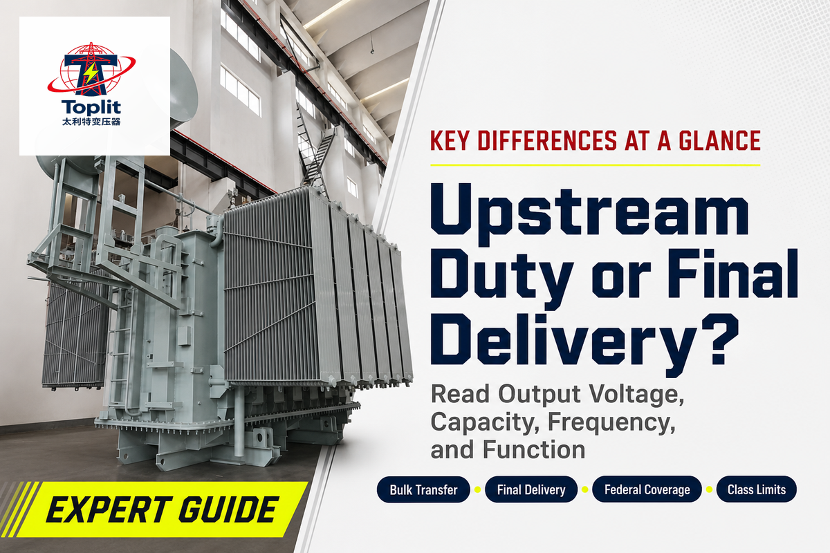
The federal rule separates covered distribution transformers from equipment outside that class; it doesn’t define a residual power-transformer class. Covered distribution transformers are normally the last step-down transformers in an electric power distribution system, feeding voltage distribution networks at 600 V or less and up to 5,000 kVA. In utility and manufacturer usage, a power transformer sits upstream, moves bulk electrical power from power generation onto a transmission line or between transmission levels, and carries no federal efficiency definition of its own.
Power transformer
Power transformers are designed for bulk power transfer in long-distance transmission and between voltage levels. They sit above the 5,000 kVA federal ceiling in most cases, run close to maximum power rating for long periods, and use the applicable IEEE C57 standard for their construction rather than a DOE distribution-transformer efficiency table.
Distribution transformer
A distribution transformer is designed for final power delivery to utilization voltage on primary power lines or inside a building. It stays energized at a low average load factor, follows minimum efficiency at a fixed per-unit load, and must clear four numeric criteria plus thirteen exclusions.
| Attribute | Power transformer | Distribution transformer | Where it stops being true |
|---|---|---|---|
| Output line voltage | Often above 600 V; no federal definition | 600 V or less for the federal class | Utilities also name equipment by position and duty |
| Input line voltage | Above 34.5 kV in most builds | 34.5 kV or less | The 34.5 kV / 4.16 kV example fails the output test and is not a distribution transformer federally |
| Capacity range | Typically above 5,000 kVA | 10–5,000 kVA liquid; 15–5,000 kVA dry-type | Catalogue labels may extend beyond the federal capacity bands |
| Rated frequency | 50 or 60 Hz | 60 Hz for the federal class | Any 50 Hz export unit is outside Subpart K entirely |
| Efficiency reference load | No federal minimum | 50% of nameplate; 35% for LV dry-type | Purchase evaluation uses a loading pattern, not the compliance point |
| Minimum efficiency example | Set by contract, not by rule | 98.70% for a 10 kVA single-phase liquid unit | Rises to 98.77% for units built on or after 23 April 2029 |
| Product standard | C57.12.00 liquid-immersed; C57.12.01 dry-type | C57.12.00 liquid-immersed; C57.12.01 dry-type | Construction changes the applicable document; neither scope creates a universal voltage split |
| Named exclusions | Not applicable | 13 types removed by 431.192(5) | Six of the thirteen turn on construction or function, not nameplate data |
| 2025 US supply deficit | 30% | 10% | Survey class labels, which need not match 431.192 |
| Demand growth since 2019 | 116% | 41% | Wood Mackenzie survey basis; not a public dataset |
| Q2 2025 lead time | 128 weeks (substation power) | 30 weeks | Generator step-up units ran to 144 weeks in the same quarter |
Sources: 10 CFR 431.192 and 431.196 (rows 1-6, 8); IEEE SA scope statements (row 7); Wood Mackenzie’s 14 August 2025 release (rows 9-10); and its Q2 2025 survey as published in POWER Magazine and reported by the Congressional Research Service (row 11).
Readers comparing the differences between the two transformer classes usually want one screen they can trust. The differences between power transformers and distribution transformers are clearest in rows one to eight, which hold up against primary text; rows nine to eleven are procurement data and carry the weaker provenance flagged in the final column. Our distribution transformer ratings and tests reference covers the single-class detail this comparison deliberately leaves out.
Where the 33 kV Figure Appears: The 33 kV Scope Boundary
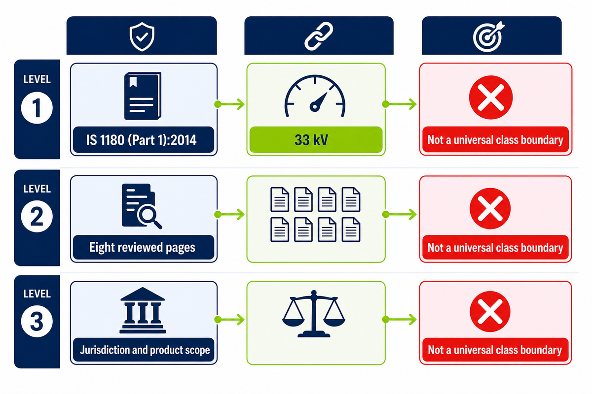
Bureau of Indian Standards document IS 1180 (Part 1):2014 carries the 33 kV figure in its own title: “Outdoor Type Oil Immersed Distribution Transformers Upto and Including 2 500 kVA, 33 kV, Specification”. The figure is genuine scope language for the products covered by that Indian standard. It is not a universal class boundary, and neither US federal rules nor the reviewed IEEE C57 scope statements use it as one.
That distinction matters because the figure appears repeatedly in explainers. We reviewed three pages selected for the highest NEURONwriter content scores and five generatively cited pages that also appeared in organic results, all captured on 3 September 2026. The set does not agree.
| Page (surveyed 3 Sep 2026) | Power transformer | Distribution transformer | Rating split |
|---|---|---|---|
| electrical-engineering-portal.com | > 33 kV | < 33 kV | 200 MVA |
| metapowersolutions.com | 33–700 kV | 230 V – 33 kV | 200 MVA |
| chintglobal.com | > 1 kV | < 1 kV | not stated |
| clelek.com | ≥ 33 kV | up to 33 kV | not stated |
| blog.powervoltgroup.com | above 33 kV | below 33 kV | not stated |
| taishantransformer.com | 66–765 kV | 11–33 kV | 25–2,500 kVA |
| upt.in | 110–800 kV | 11–33 kV | 100 MVA |
| transformerindia.com/usa | 66 kV and above | up to 33 kV | not stated |
First-party comparison sample captured 3 September 2026: three highest content-score competitors plus five pages cited generatively and present in organic results. Domains are shown so the sample can be reproduced.
Four voltage boundaries and three rating boundaries sit in that table. Transformerindia.com leaves everything between 33 kV and 66 kV unclassified by its own two rules. Chintglobal.com’s 1 kV line would reclassify every 12.47 kV pole-mounted unit in North America as a power transformer. Yet another convention circulates in NETA-framed material, putting the break at 500 kVA while noting that IEEE guidance discourages classifying by kVA alone.
This does not make 33 kV a universal classification boundary. It means applicability depends on jurisdiction and product scope. For an Indian project, confirm whether the relevant part of IS 1180 covers the construction and rating; in a US procurement document, use the federal inputs rather than importing the 33 kV and 2,500 kVA pair.
How US Federal Rules Define a Distribution Transformer: The Four-and-Thirteen Federal Boundary
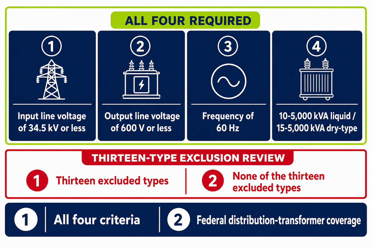
Federal law defines the class by four numeric tests joined by “and”, then removes thirteen named transformer types from it. Qualification requires meeting all four criteria while belonging to none of the thirteen excluded types. The definition lives in 10 CFR 431.192 and applies for the purposes of that subpart’s energy conservation requirements.
📐 The four inputs, quoted from 10 CFR 431.192
- “Has an input line voltage of 34.5 kV or less”
- “Has an output line voltage of 600 V or less”
- Has a rated “frequency of 60 Hz”
- “Has a capacity of 10 kVA to 5000 kVA for liquid-immersed units and 15 kVA to 5000 kVA for dry-type units”
Then comes the part almost no comparison article carries. Paragraph (5) states that the term “does not include a transformer that is an”: autotransformer; drive (isolation) transformer; grounding transformer; machine-tool (control) transformer; nonventilated transformer; rectifier transformer; regulating transformer; sealed transformer; special-impedance transformer; testing transformer; transformer with tap range of 20 percent or more; uninterruptible power supply transformer; or welding transformer.
Six of those thirteen, drive, grounding, rectifier, regulating, special-impedance and testing, describe a unit’s intended function rather than its nameplate data. For example, a 480 V drive isolation transformer and an ordinary 480 V distribution transformer can carry identical voltage, frequency and kVA data. The rule separates them on construction and intended function, which means the screen is four nameplate checks followed by a thirteen-item review that sometimes needs the specification or the design documentation.
Two limits are worth stating plainly. The definition governs DOE efficiency rules and nothing else: engineering usage, utility practice and procurement language are three further vocabularies the regulation doesn’t reach. And it isn’t the only official US number in circulation; DOE’s own explainer page for buyers still prints a 10 kVA to 2,500 kVA capacity range, half the ceiling in the binding text and in the Congressional Research Service’s April 2026 report.
What IEEE C57 Standards Cover for Each Class
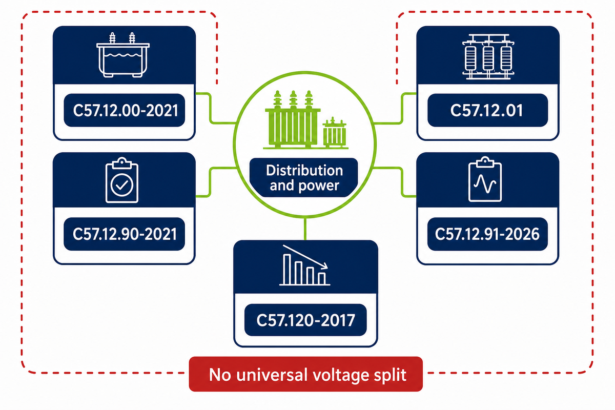
IEEE C57.12.00-2021 scopes “liquid-immersed distribution, power and regulating transformers” in a single sentence, and its companion test code repeats the combined wording. That scope statement doesn’t supply a single voltage boundary between the terms. Anyone citing this standard as the authority for a universal 33 kV or 66 kV split is claiming a dividing rule that its published scope doesn’t state.
| Document | Subject | Class covered | Status |
|---|---|---|---|
| C57.12.00-2021 | General requirements, liquid-immersed | Distribution and power | Current; no revision since 2021 |
| C57.12.90-2021 | Test code, liquid-immersed | Distribution and power | Current |
| C57.12.01 | General requirements, dry-type | Distribution and power | Reported under revision in May 2026 |
| C57.12.91-2026 | Test code, dry-type | Distribution and power | IEEE page lists an approved draft revision |
| C57.94 | Installation and maintenance, dry-type | Distribution and power | Reported under revision in May 2026 |
| C57.96 | Loading guide, dry-type | Distribution and power | Reported under revision in May 2026 |
| C57.120-2017 | Loss evaluation | Distribution, power and reactors | Active; PC57.120 PAR approved 19 Jun 2025 |
| C57.166 | Insulating liquids | Both, consolidated | Consolidation described in the May 2026 committee report |
| C57.12.00-1968 | Earlier general requirements | Distribution and power | Superseded |
Sources: IEEE SA records for C57.12.00, IEEE C57.120 and IEEE C57.12.91, plus the IEEE Transformers Committee report cited below.
A May 2026 committee report said six of the Dry-Type Transformers Subcommittee’s fourteen standards were under revision. It identified C57.12.01, C57.94, C57.12.91 and C57.96 among the expected 2026 publications and described C57.166 as a consolidation project. These are dated committee-report status statements, not proof that every revision has since been published.
Scott Reed, President of MVA and Vice Chairman of the IEEE Transformers Committee, NETA World Journal, 9 May 2026
How can you tell if a transformer is a power or distribution transformer?
Read the nameplate against the federal four inputs first, because that’s the only test with legal force in the United States. Output line voltage does most of the work: 600 V or less and the unit is a candidate; anything higher and it’s outside the distribution class regardless of how small it is. Then check capacity against the 5,000 kVA ceiling, confirm 60 Hz, and run the thirteen exclusions.
If the unit is a rectifier, drive isolation, grounding or regulating transformer, it leaves the class no matter what the four numbers say. What you can’t do is settle it from a voltage headline: C57.12.00 covers both liquid-immersed classes without distinguishing them, while dry-type equipment uses the corresponding dry-type documents. Our power transformer guide works through the upstream side, and transformer BIL covers the insulation coordination governed by the C57 series.
Voltage Levels, kVA and the Real Boundary Numbers
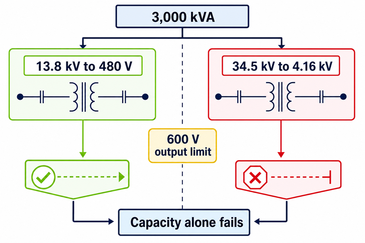
High voltage levels and capacity ranges overlap between the two classes far more than any comparison table admits. For example, assuming 60 Hz and that none of the thirteen exclusions applies, a 3,000 kVA unit stepping 13.8 kV down to 480 V is a distribution transformer federally; the same rating stepping 34.5 kV down to 4.16 kV is not, because 4,160 V exceeds the 600 V output limit. The common assumption that capacity alone settles the class fails this side-by-side test.
Commercial catalogue labels can extend beyond one or more federal inputs. A unit sold under a distribution-series heading may still fall outside the federal definition because of its voltage pair, frequency, capacity or intended function. Models above 5,000 kVA, above 600 V output, or otherwise outside one of the four conditions are not federal distribution transformers, yet that fact alone does not assign them a power-transformer label. The catalogue heading and the regulatory class are different vocabularies.
Can a power transformer be used as a distribution transformer?
Physically yes. Assuming 60 Hz and that none of the thirteen exclusions applies, a 5,000 kVA 34.5 kV / 480 V unit satisfies every federal criterion, whatever the vendor calls it. The consequences are regulatory, not electrical. Such a unit must meet the minimum efficiency in 10 CFR 431.196 to be sold in the United States when it clears the thirteen exclusions.
For example, an application can fail when a distribution transformer is used outside its specified duty: inadequate insulation level or short-circuit withstand can become the limiting factor before nameplate rating. Sizing method is a separate exercise; our transformer kVA sizing guide carries the arithmetic, and pole-mounted vs pad-mounted transformer covers the mounting decision that follows it.
When the federal class label should not drive your specification
Three situations make the federal screen the wrong tool. First, exported equipment: a 50 Hz unit for a non-US grid falls outside Subpart K entirely, so quoting 10 CFR efficiency tiers in that specification imports a rule that does not apply and may conflict with the destination’s own standard.
Second, the screen is wrong for any of the thirteen excluded types, including a rectifier transformer for an electrolysis line or a testing transformer. DOE efficiency levels do not apply to those excluded types, and writing them into the specification creates an unsatisfiable requirement. Third, sub-transmission service around 34.5 kV / 4.16 kV, where the unit misses the distribution class on output voltage yet large-power practice usually starts far above that rating; here the useful specification is IEEE C57.12.00 plus explicit BIL, impedance and loss-evaluation terms, not a class name at all. Practising engineers on utility forums describe the same ambiguity from the other direction, noting how inconsistently the two terms get used between utilities and manufacturers for identical equipment. The safe habit is to specify the four measurable quantities and let the class label follow.
Where the Two Classes Meet: The Substation Interface
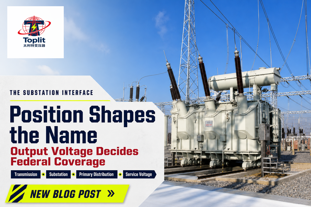
Within electrical power systems, substation transformers sit at the handover between the transmission network and the distribution system, and most of them aren’t distribution transformers in the federal sense. DOE stated in its 2024 rulemaking that distribution substation transformers would typically fall outside the definition because their output voltage exceeds 600 V. The power delivery criterion doing the work is output voltage, not physical size.
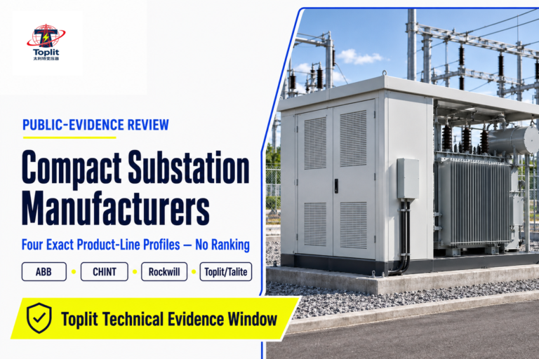
Power flow position and duty shape the vocabulary used on the feeder. Within a power system, transmission substations route three-phase power from high-voltage bulk supply down to sub-transmission voltage or into the primary distribution network, and utilities commonly call the unit doing that job a power transformer. Further along, step-down transformers on poles or pads make the final step to 240/120 V or 480 V and meet the distribution definition when all federal criteria and none of the exclusions apply. Compact substations package switchgear and a transformer into one enclosure and can contain either, depending on the secondary they serve; our compact substation guide covers that boundary.
Practitioner threads describing real feeders make the same point in plainer language: engineers name equipment by where it sits and what it feeds, and the naming rarely matches the regulatory class boundary. Both descriptions are correct within their own vocabulary, which is precisely why a specification should state the voltages rather than the label.
Load Profile, Losses and Why Efficiency Is Measured Differently
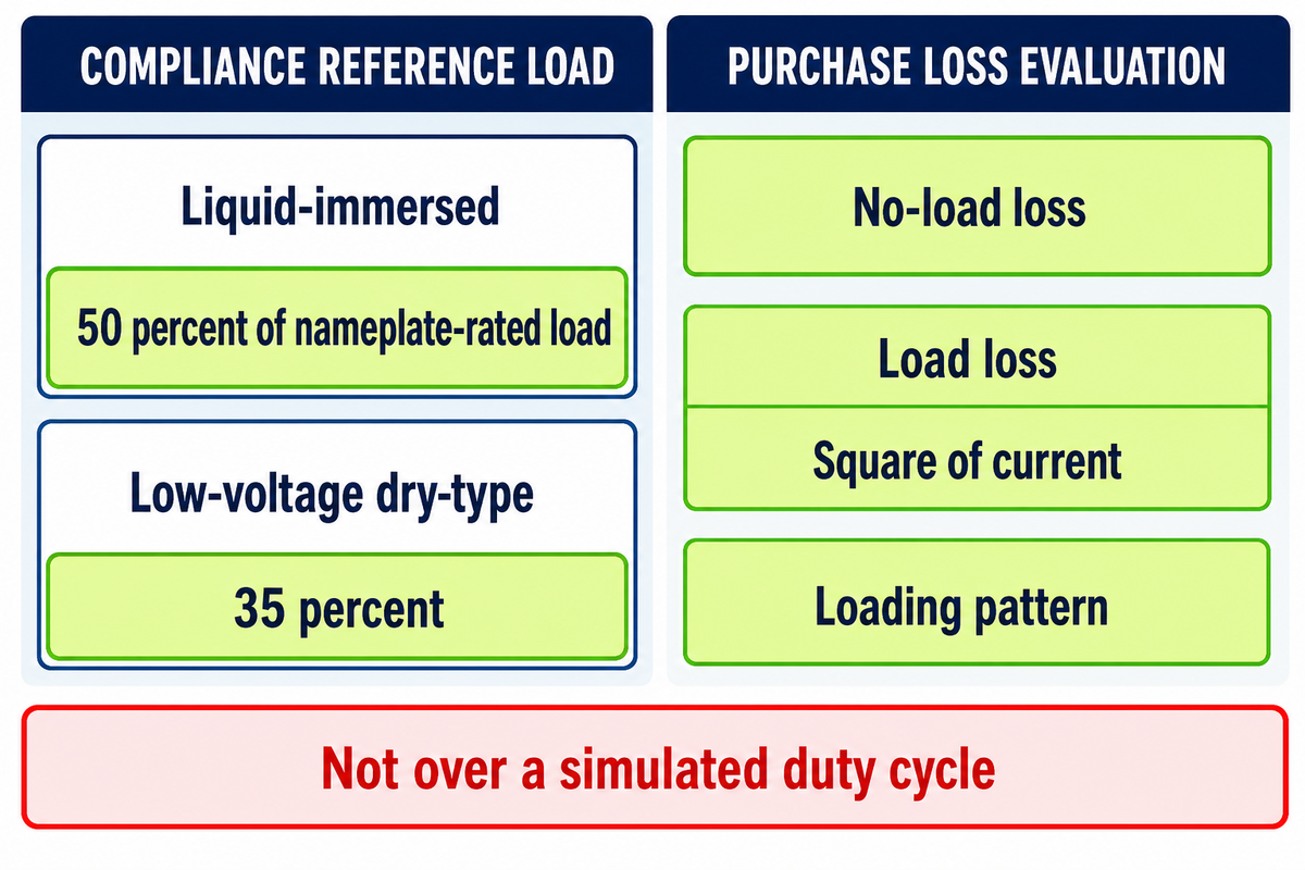
Compliance efficiency is tested at one fixed per-unit load, not over a simulated duty cycle. That sounds odd until you separate compliance from purchasing: the rule needs one repeatable laboratory point, while a buyer needs the losses over the load profile the unit will actually see. DOE says Appendix A contains the method for determining efficiency at a specified per-unit load, the metric on which the standards are based.
The fixed point is not one number. Table 5 of 10 CFR 431.196 sets 98.70% for a 10 kVA single-phase liquid-immersed unit, with the table note reading “All efficiency values are at 50 percent of nameplate-rated load”. Low-voltage dry-type tables in paragraph (a) are stated at 35 percent instead. So the rule uses two reference load points chosen by insulation class, not the “full load versus all-day” pairing that circulates online, which appears in neither table.
Transformers lose electrical energy two ways, and the split is what makes the reference point matter. No-load loss runs whenever the unit is energised, which for a distribution transformer means every hour of the year. Load loss rises with the square of current, so it dominates only when the unit is worked hard. Distribution transformers are designed around a low average load factor and therefore around no-load loss, unlike power transformers, which spend long periods near their maximum power rating where load loss carries the energy cost.
📐 Worked example: what the two loss terms cost over a year
Take a 500 kVA unit with 600 W no-load loss and 5,000 W load loss at rated current, at an average load factor of 30 percent.
No-load energy: 0.6 kW × 8,760 h = 5,256 kWh/year. Load loss scales with the square of the load ratio: 5.0 kW × 0.30² = 0.45 kW, so 0.45 kW × 8,760 h = 3,942 kWh/year.
No-load loss wins at 57 percent of the total. Raise the load factor to 0.6 and load loss becomes 1.8 kW → 15,768 kWh/year, four times the no-load figure. The crossover on these inputs sits near a 0.35 load factor; substitute your own nameplate losses and your own load factor to find yours.
That arithmetic is why loss evaluation is a formal purchasing method rather than a rule of thumb. IEEE C57.120-2017, “Guide for Loss Evaluation of Distribution and Power Transformers and Reactors”, converts “the costs of energy, power, financing, and the loading pattern of equipment” into monetary values per kilowatt of losses, and covers both classes in one document. PC57.120 was approved as an active revision project on 19 June 2025.
What is the efficiency of power transformer vs distribution transformer?
US distribution transformers carry a legal minimum: 98.70% for a 10 kVA single-phase liquid-immersed unit at 50 percent load, rising to 98.77% for units manufactured on or after 23 April 2029. Larger units sit higher still. Power transformers have no federal minimum; their efficiency is set by contract and by loss evaluation.
The common assumption that distribution transformers run at “50–70% efficiency” falls tens of percentage points below the federal table, as does a second claim giving 90 percent against 80 percent for a standard power transformer. The 50–70 figure began life on a 2011 page as the load at which peak efficiency occurs, lost its noun in copying, and now appears on at least four sites, including the page currently ranking first. One reader posted the correction in that page’s comments in 2015; the body text still carries the error today.
Adjacent Terms People Confuse With Both
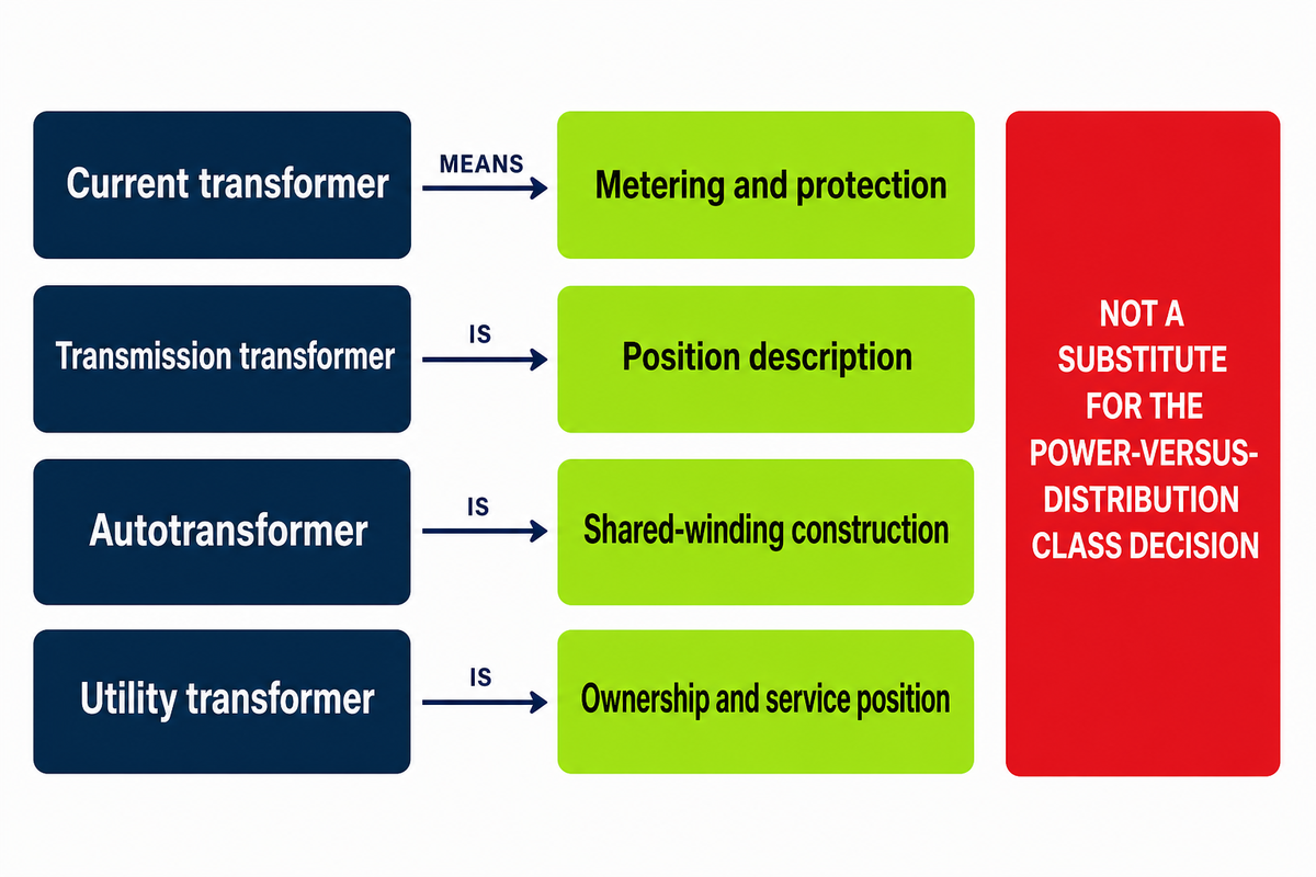
Measurement transformers sit outside this comparison. Current transformers and other instrument transformers produce a scaled, isolated signal for metering and protection and carry a burden measured in volt-amperes rather than kVA; they neither transfer bulk power nor deliver electrical energy to a customer. This classification problem matters because the official IEEE page for active standard C57.13-2016 covers measurement and control rather than load delivery. For example, a 600:5 current transformer feeds a 5 A signal to a meter or relay; it doesn’t energize a 480 V bus.
Three more terms cause trouble. Transmission transformer isn’t a separate class but a power transformer described by where it works. An autotransformer shares one winding between primary and secondary, gives no galvanic isolation, and is the first of the thirteen types excluded from the federal distribution class. Utility transformer names an ownership and service position rather than an equipment class; our companion article on utility transformer vs distribution transformer works that distinction through in full.
Procurement Reality: The Two-Speed Shortage
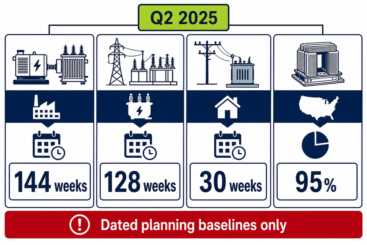
Power transformers and distribution transformers were moving in opposite directions through 2025, so a project schedule built on one class’s lead time will miss badly for the other. Substation power units ran at roughly 128 weeks in the second quarter of 2025 while distribution transformer waits had come back down to about 30 weeks. Treating “the transformer shortage” as one queue is the scheduling error.
144 weeks
Generator step-up lead time, Q2 2025
128 weeks
Substation power transformer lead time
30 weeks
Distribution transformer wait time
95%
Older industry estimate of US transformer cores using GOES
Demand explains the divergence, but the published categories must stay separate. Wood Mackenzie’s August 2025 public analysis put demand growth since 2019 at 116 percent for power transformers and 41 percent for distribution transformers. POWER Magazine’s January 2026 account of the firm’s second-quarter survey reported 274 percent for generator step-up units, 116 percent for substation power units, 119 percent for its broader power category and 34 percent for distribution equipment; those scopes aren’t interchangeable, and none is a live 2026 spot reading. The POWER Magazine report and the Congressional Research Service use different category sets; the latter also reported that inflation-adjusted producer prices for both classes rose about 40 percent from 2020 to 2024 and that 60 to 80 million distribution transformers are in service across the country.
Both classes then compete for one upstream input. DOE’s June 2026 Request for Information records a single domestic manufacturer of grain-oriented electrical steel and a single domestic manufacturer of amorphous alloy, and asks whether its own efficiency standards conflict with Presidential Determination No. 2026-10 of 20 April 2026, which named transformers and electrical core steel as essential to national defence. The Congressional Research Service reported in April 2026 that an older industry estimate used in policy discussion put grain-oriented electrical steel in 95 percent of US transformer cores; treat that figure as a dependency indicator, not a current market-share measurement. A shortage in the domestic material base can therefore reach both queues at once, which is why the two clocks can diverge on demand yet move together on price.
One caution on the class labels above: market-survey categories are survey segments, not regulatory classes, and need not track 10 CFR 431.192. We use them because they are the only class-split procurement data available in this research set. The same caveat is easy to demonstrate; one widely sold market dataset books a large share of US “distribution transformer” revenue to 10–100 MVA and above-100 MVA bands, which can’t contain a distribution transformer under a 5,000 kVA ceiling. Treat the 2025 lead times as dated planning baselines only. For a current project, request written lead times for the exact power transformers and distribution units in the specification rather than carrying those survey clocks into 2027.
Choosing the Right Transformer for Your Project
Selecting the right transformer starts with output voltage as the quickest federal screen, not a complete industry classification. If the equipment on the far side runs at 600 V or less, the unit is within the applicable capacity band at 60 Hz, and none of the thirteen exclusions applies, it’s a federal distribution transformer and the DOE efficiency levels apply. Otherwise it’s outside that regulated class; specify its actual duty, voltage pair, capacity, losses and applicable IEEE C57 requirements before choosing the commercial label.
| Scenario | Class | Why | Limitations / not suitable for |
|---|---|---|---|
| 13.8 kV feeder to 480 V plant bus, 2,500 kVA | Distribution | Meets all four federal inputs, assuming 60 Hz | Not if any of the thirteen exclusions applies, including drive isolation duty |
| 34.5 kV to 4.16 kV, 5,000 kVA | Commonly power | Substation duty; output also exceeds 600 V | No DOE efficiency tier exists; set losses by contract |
| Pad-mounted, 1,000 kVA, 12.47 kV to 208Y/120 V | Distribution | Classic service transformer duty | Pad and seismic anchorage add lead time not in the transformer quote |
| Generator step-up, 18 kV to 230 kV | Power | Transmission-level output | 144-week lead times in Q2 2025; book before design freeze |
| Data hall, 2,000 kVA cast-resin dry-type indoors | Distribution (MV dry-type) | 601 V–34.5 kV primary, 600 V secondary | Nonventilated designs are excluded from the federal class |
| Electrolysis or plating line rectifier duty | Neither | Rectifier transformers are excluded outright | Do not write DOE efficiency levels into this specification |
| Export order, 11 kV to 415 V, 50 Hz | Outside Subpart K | Federal class requires 60 Hz | Destination standard governs; verify whether the applicable part of IS 1180 covers the Indian product scope |
| Utility feeder regulation | Neither | Regulating transformers are excluded | Specify against the applicable IEEE C57 standard for the construction |
| Solar or storage collector, 34.5 kV output | Commonly power | Collector-system duty; output also exceeds 600 V | Loss evaluation matters more than class label here |
| Rural single-phase, 25 kVA pole-mounted | Distribution | Bottom of the 10–5,000 kVA band | Per-unit prices rose sharply from 2020 in some utility procurements |
Once the class is settled, build the specification from measurable quantities rather than from a label. Copy the table below straight into your quote request.
RFQ checklist — copy these into your quote request:
| Parameter | What to state | Why it matters | How to verify |
|---|---|---|---|
| Primary and secondary voltage | Exact values, e.g. 12,470 V to 480Y/277 V | Provides the first federal coverage screen | Nameplate drawing at approval stage |
| Rated capacity | kVA: 10–5,000 liquid or 15–5,000 dry-type | Outside the applicable band the DOE tables stop applying | Routine test report under C57.12.90 for liquid-immersed or C57.12.91 for dry-type |
| Efficiency at reference load | Percent at 50% PUL (35% for LV dry-type) | Legal minimum for the distribution class | Certified test data against 10 CFR 431.196 |
| No-load and load loss, in watts | Both figures separately, not a single efficiency | Loss evaluation needs them split | Measure under the applicable C57.12 test code; evaluate per C57.120 |
| Basic impulse insulation level | BIL in kV for each winding | Governs insulation coordination and impulse withstand | Impulse test certificate |
| Impedance | Percent on rated base, with tolerance | A special-impedance build leaves the federal class | Impedance test in the routine report |
| Tap range | Percent above and below nominal | A range of 20 percent or more excludes the unit | Tap changer schedule on the drawing |
| Expected load factor | Average per-unit load over 24 hours | Sets which loss term dominates your energy cost | Metered data or feeder study |
The one line to remember
In the United States, 10 CFR 431.192 defines federal distribution-transformer coverage with four numbers and thirteen exclusions, not a 33 kV headline. It does not positively define power transformers, so specify the duty, voltages, capacity and losses before applying a class label.
For supplier qualification, use our distribution transformer manufacturers page as the next step, then compare the published distribution transformer product family against the voltage, capacity and duty in your specification.
Send the four numbers, primary voltage, secondary voltage, kVA and frequency, plus the intended function and construction details. We can run the initial screen; final classification also requires the thirteen-item exclusion review.
Frequently Asked Questions
What is a power transformer and a distribution transformer?
A power transformer moves bulk power between generation and transmission or between transmission voltage levels, while a distribution transformer makes the final step down to 600 V or less for the customer.
A power transformer moves bulk power between generation and transmission or between transmission voltage levels, while a distribution transformer makes the final step down to 600 V or less for the customer. In the United States only the second term has a legal definition: 10 CFR 431.192 sets 34.5 kV input, 600 V output, 60 Hz, 10–5,000 kVA for liquid-immersed units and 15–5,000 kVA for dry-type units, then excludes thirteen named types. Equipment outside that definition is outside the federal distribution class, but its duty and the applicable standards determine whether industry calls it a power transformer.
What is the purpose of a distribution transformer?
A distribution transformer converts primary distribution voltage to the utilisation voltage a building or machine actually runs on, typically 480 V, 208Y/120 V or 240/120 V.
A distribution transformer converts primary distribution voltage to the utilisation voltage a building or machine actually runs on, typically 480 V, 208Y/120 V or 240/120 V. Because it stays energised year-round at a modest average load, its no-load loss usually dominates its lifetime energy cost, which is why federal efficiency rules target this class and not the power class. Between 60 and 80 million of them are in service across the United States.
What are the four main types of transformers?
No single canonical list of four exists; US federal rules instead recognise liquid-immersed, low-voltage dry-type and medium-voltage dry-type distribution transformers, with everything else falling outside the class.
No single canonical list of four exists; US federal rules instead recognise liquid-immersed, low-voltage dry-type and medium-voltage dry-type distribution transformers, with everything else falling outside the class. Grouping by function gives a different four: power, distribution, instrument and specialty. Grouping by construction gives another. Any article presenting one list of four as the answer is presenting a convention, not a standard.
Are power transformers AC or DC?
A power transformer is used only with alternating current in normal grid service because changing magnetic flux transfers energy through electromagnetic induction between its primary and secondary windings.
A conventional grid power transformer operates on alternating current because electromagnetic induction needs changing flux; high-voltage direct-current links place transformers on the alternating-current side of the converters.
Where are power transformers used vs distribution transformers?
Power transformers sit at generating stations and transmission substations; distribution transformers sit at the end of primary distribution lines, on poles, on pads or inside buildings.
Power transformers sit at generating stations and transmission substations; distribution transformers sit at the end of primary distribution lines, on poles, on pads or inside buildings. The transformer at a distribution substation is the awkward case: it looks like the boundary between the two, and DOE has stated it would typically not meet the federal distribution definition because its output voltage exceeds 600 V. Utilities and manufacturers frequently name that same unit differently, which is why a specification should state the voltage pair rather than the class name.
What is the difference between a current transformer and a distribution transformer?
A current transformer produces a scaled, isolated measurement signal for metering and protection equipment; a distribution transformer delivers usable electrical power to a customer’s load in the distribution network.
A current transformer produces a scaled measurement signal for metering and protection; a distribution transformer delivers usable power to a load. Their ratings reflect that: a current transformer is specified by ratio, accuracy class and burden in volt-amperes, while a distribution transformer is specified in kVA with an efficiency requirement attached. They also sit in different IEEE standard series.
About This Analysis
This analysis addresses the repeated use of a 33 kV headline in US-facing comparison pages even though US federal rules use a different multi-input screen. The federal boundary figures were checked in primary text on 3 September 2026, including the thirteen exclusions and the two reference load points. Where procurement data is survey-based rather than regulatory, the article states the source chain and date.
References & Sources
- 10 CFR 431.192, Definitions US Government Publishing Office, eCFR
- 10 CFR 431.196, Energy conservation standards and effective dates US Government Publishing Office, eCFR
- Energy Conservation Standards for Distribution Transformers, final rule, 89 FR 29834 (22 April 2024) US Department of Energy
- Request for Information, 91 FR 35903 (15 June 2026) US Department of Energy
- Distribution Transformers US Department of Energy, Clean Manufacturing and Energy Innovation
- Report R48933 on transformer supply and demand (23 April 2026) Congressional Research Service
- IEEE C57.12.00, General Requirements for Liquid-Immersed Distribution, Power, and Regulating Transformers IEEE Standards Association
- IEEE C57.120-2017, Guide for Loss Evaluation of Distribution and Power Transformers and Reactors IEEE Standards Association
- IEEE C57.12.91-2026, Test Code for Dry-Type Distribution and Power Transformers IEEE Standards Association
- IEEE C57.13-2016, Standard Requirements for Instrument Transformers IEEE Standards Association
- IEEE Transformers Committee Report (9 May 2026) NETA World Journal
- IS 1180 (Part 1):2014, Outdoor Type Oil Immersed Distribution Transformers Upto and Including 2 500 kVA, 33 kV Bureau of Indian Standards
- Transformers in 2026: Shortage Scramble or Self-Inflicted Crisis? (2 January 2026) POWER Magazine
- Power and distribution transformers will face supply deficits of 30% and 10% in 2025 (14 August 2025) Wood Mackenzie
- Solid State Devices and the Power Grid (February 2026) Idaho National Laboratory, GridTechPedia
Related Articles
- Utility transformer vs distribution transformer: ownership and service position against equipment class
- Power transformer guide: the upstream class in detail
- Distribution transformer ratings and tests: single-class reference depth
- Transformer kVA sizing guide the arithmetic this article hands off
- Compact substation guide packaged switchgear and transformer sets
![Pad-Mounted Transformer: How It Works [2026 Guide]](https://toplit-transformer.com/wp-content/uploads/2026/08/pad-mounted-transformer-guide-featured-150x150.png)
![Single Phase Pad Mounted Transformer Guide [2026]](https://toplit-transformer.com/wp-content/uploads/2026/08/single-phase-pad-mounted-transformer-guide-featured-1-150x150.png)