Get in touch with Talite Transformer Co., Ltd Company

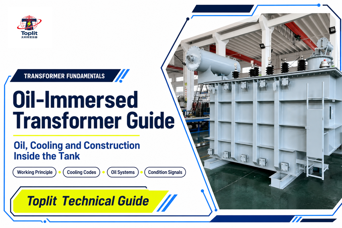
Transformer Fundamentals · Oil, Cooling & Construction
An oil-immersed transformer is a liquid-insulated unit that places its active core-and-winding assembly inside a filled tank. The liquid supports electrical insulation and carries heat toward the tank and cooling surfaces. That construction label doesn’t, by itself, state the unit’s voltage class, kVA or MVA rating, grid role, cooling capacity, or site suitability.
Updated September 4, 2026; System Reading Guide for engineers, project teams, asset owners, technical purchasers.
Read the system in four paths
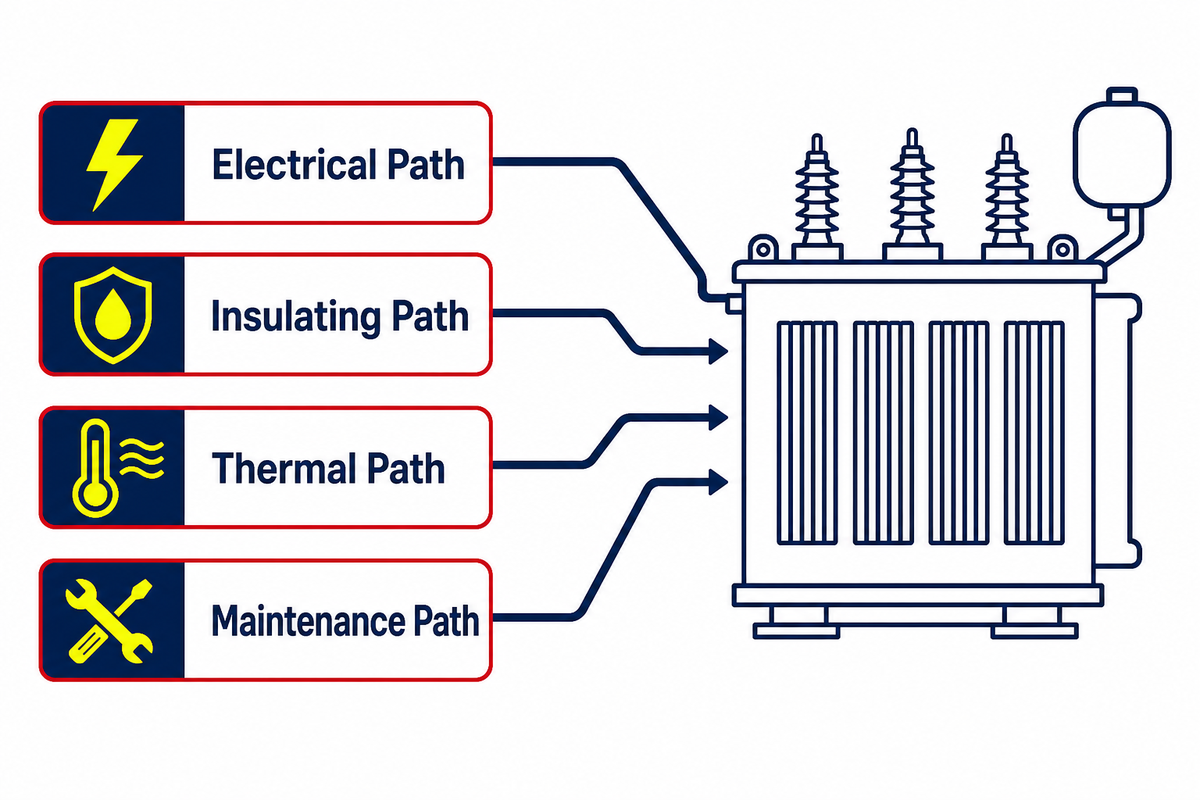
Read the electrical path first, then the insulating, thermal, and maintenance paths. Names, gauges, codes, and lab reports each describe only part of the whole system.
When the task becomes model selection, rating confirmation, or project configuration, use Toplit’s oil-immersed transformer solutions. This article exclusively covers construction literacy.
1. What Is an Oil-Immersed Transformer?
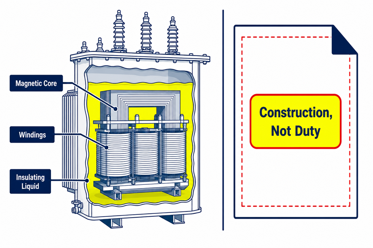
An oil-immersed transformer is a type of transformer whose magnetic core and windings are contained in a tank filled with oil or another approved insulating liquid. You may also see oil-filled transformer or the broader term liquid-filled transformer. The liquid helps insulate energized conductors and acts as a cooling medium.
The name describes construction, not duty. Power and distribution transformers can both use liquid insulation. One substation unit, one renewable-energy collector transformer, and one smaller power-distribution unit may share the same basic medium while having very different high-voltage and lower-voltage interfaces, ratings, accessories, and evidence requirements.
Toplit’s commercial page, for example, publishes separate ranges for 6/6.3/10 kV and 35/38.5 kV classes. That shows why oil-immersed can’t select a unit: the exact voltage level, rated capacity of the transformer, frequency, impedance, vector group, tap range, loss schedule, site conditions, and applicable rules still need to be defined. The mismatch risk is real because a 36 kV search phrase or a 5 MVA label does not establish the complete application duty. IEC 60076-1 provides general requirements, but the project specification and unit records must supply the missing particulars.
That distinction also prevents a common regulatory mix-up. The U.S. Department of Energy uses a specific definition for a covered distribution transformer; it’s narrower than the everyday engineering use of liquid-immersed transformer. Don’t assume that every oil-filled unit falls into the same market category.
Search results also group many types of oil-immersed equipment used across transmission and distribution. Those electrical transformers aren’t interchangeable. Any type of oil-immersed transformer advertised from kVA to 5 MVA may serve power systems at a lower or higher voltage, but that range still doesn’t define project fit. Voltage transformers are a separate instrument-transformer category and shouldn’t be confused with the power grid equipment discussed here.
2. Oil-Immersed Transformer Working Principle: Core, Windings, and Liquid
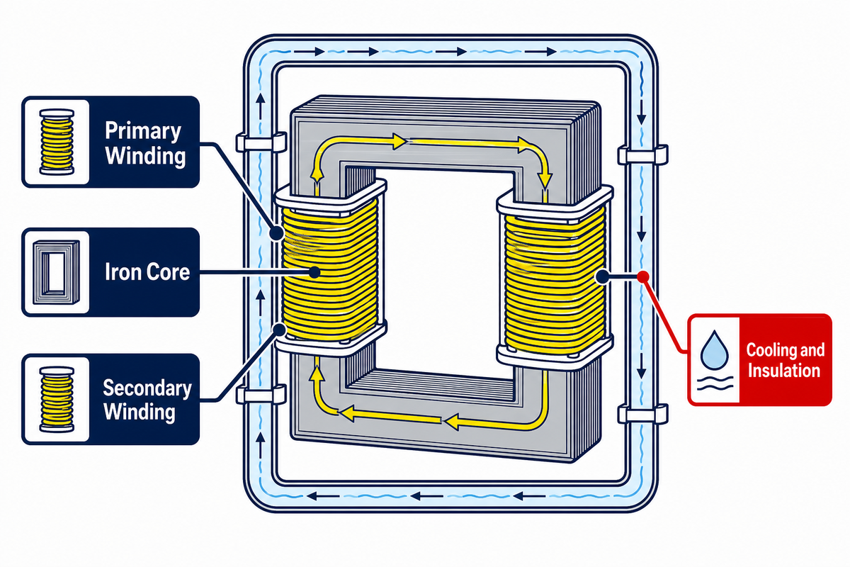
The working principle of oil-immersed transformer construction begins with electromagnetic induction. Alternating current in the primary winding produces a changing magnetic field in the iron core. That changing flux links the secondary winding and induces voltage. The ideal transformation ratio follows the turns ratio:
Vprimary / Vsecondary ≈ Nprimary / Nsecondary
In a simple 10:1 teaching example, one secondary turn for every ten primary turns produces an idealized 10:1 voltage ratio. This dimensionless example ignores winding resistance, leakage flux, excitation current, impedance, dielectric clearances, losses, temperature, and loading. It isn’t a project calculation.
How do liquid-filled transformers work?
The magnetic circuit carries flux; the windings transfer electrical energy by the principle of electromagnetic induction; the insulation system keeps conductors and grounded parts separated; and the liquid transports heat from the active part toward tank walls or radiators. Bushings provide the insulated path between internal windings and external circuits. A tap changer alters the effective turns relationship within its designed range. Real transformer performance is the result of these connected systems, not the turns ratio alone.
The oil doesn’t create the voltage transformation. The core and winding arrangement does that. The liquid supports the environment in which the electrical and thermal design operates: it helps cool and insulate, but it can’t compensate for an unsuitable rating or missing project inputs. That distinction matters in a 50 Hz or 60 Hz application because treating the fluid as the source of transformation hides the separate magnetic, dielectric, and thermal design checks required by IEC 60076-1.
3. Inside the Tank: The Four Functional Paths
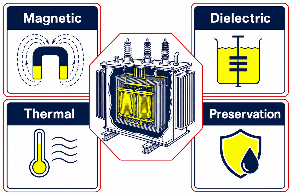
Component lists become more useful when every item is assigned to a functional path. The Four-Path Transformer Reading Map below links components to what they can help you understand—and to what they can’t prove alone. This avoids the risk of treating one observation as evidence for the entire unit.
| Path | Main elements | Job | Evidence boundary |
|---|---|---|---|
| Magnetic | Core, limbs, yokes, windings | Link flux and transform voltage | A turns ratio does not establish losses, impedance, or temperature rise. |
| Dielectric | Liquid, paper/pressboard, clearances, bushings | Insulate conductors and control electrical stress | One oil test does not prove the whole insulation system’s condition. |
| Thermal | Liquid passages, tank, radiators, pumps, fans | Move heat from losses to the surroundings | A cooling code does not set a universal load allowance. |
| Preservation | Conservator, membrane, breather, gas space, sealed tank, relief devices | Manage liquid expansion and interaction with air or gas | A gauge or accessory name does not identify every preservation arrangement. |
Some items cross several functional paths. Bushings belong to the dielectric path and also carry current to the external circuit; the cooling radiators connect to the thermal path but their valves will determine its effectiveness; the tap changer can adjust the ratio (electrical path) and may include its own tank or fluid handling system. It’s a guide, not a troubleshooting tool.
The practical rule is to evaluate every observation through its functional path. Normal liquid temperature doesn’t prove dielectric condition, and a satisfactory turns-ratio measurement doesn’t verify cooling availability. Treating the core and windings, liquid, tank, and accessories as one monolithic object obscures those limits.
4. What Transformer Oil Does, and What It Cannot Prove
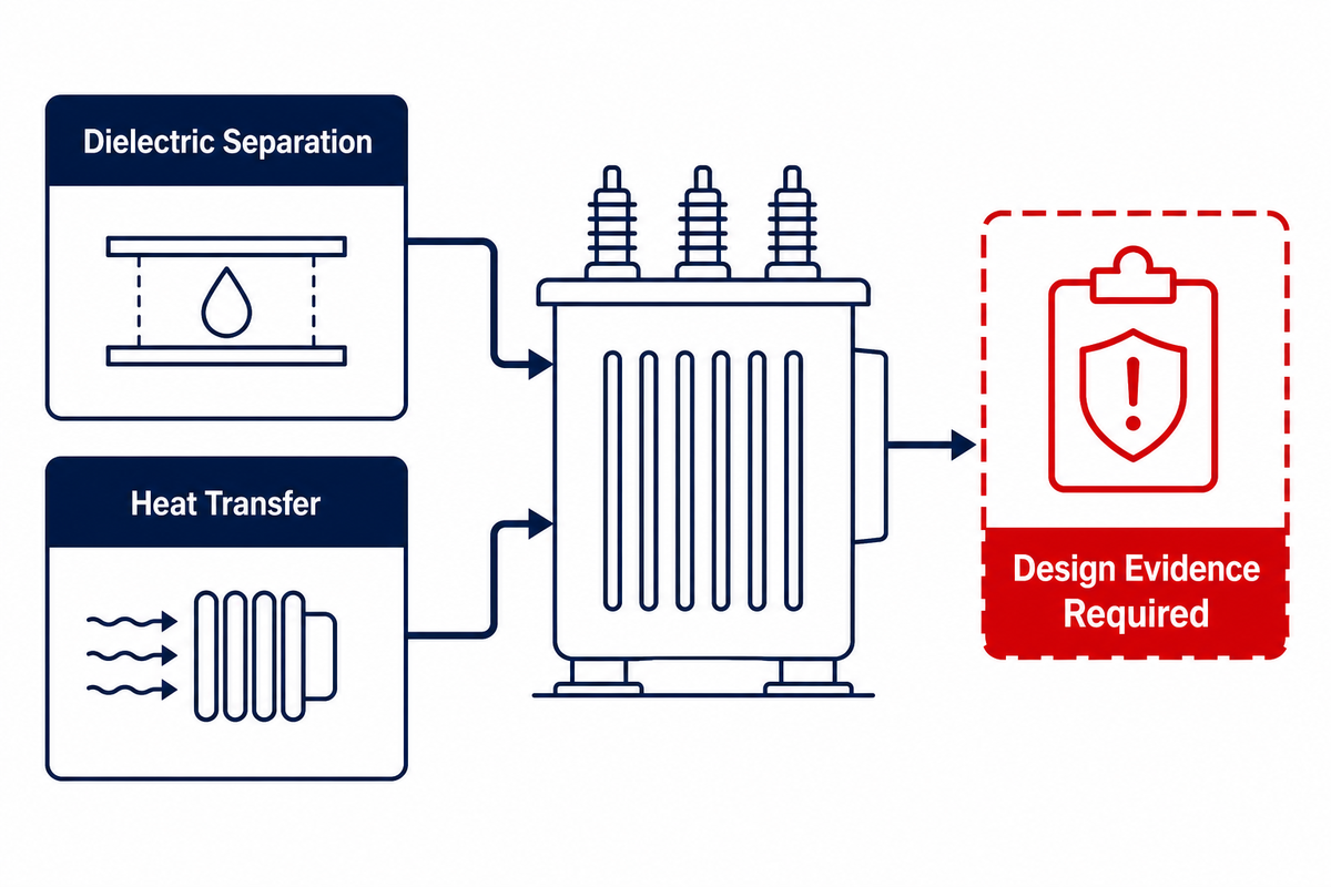
Transformer oil has two linked jobs: dielectric separation and heat transfer. CIGRE summarizes both functions in one short statement:
“Liquids serve two main functions: as a cooling liquid and as an electrical insulator.”
The fluid fills spaces around the active part, participates in the insulation system, and transfers heat to cooling surfaces. The practical risk is overclaiming from a fluid label because the name alone does not verify dielectric clearances, temperature-rise performance, or compatibility with every gasket, coating, and insulating material.
Why are transformers submerged in oil?
Immersion lets the liquid contact the core-and-winding assembly and flow through designed passages. As hotter liquid rises and cooler liquid returns, natural convection can carry heat toward the tank or radiator. Pumped systems add forced circulation. The insulating oil also occupies spaces that would otherwise need a different dielectric design. “Filled with oil” still says nothing about allowable operating temperature, loading, or service life.
Mineral oil, natural ester, and synthetic ester are fluid families, not interchangeable approvals. They can differ in cooling behavior, dielectric performance, oxidation response, moisture interaction, fire properties, and material compatibility. CIGRE notes that established mineral-oil dimensioning rules aren’t automatically applicable to newer liquids. Even a phrase such as “environmentally friendly vegetable oil” is too broad to establish biodegradability, fire classification, corrosion behavior, or destination acceptance for a specific product.
5. Cooling Codes Explained: ONAN, ONAF, OFAF, and ODAF
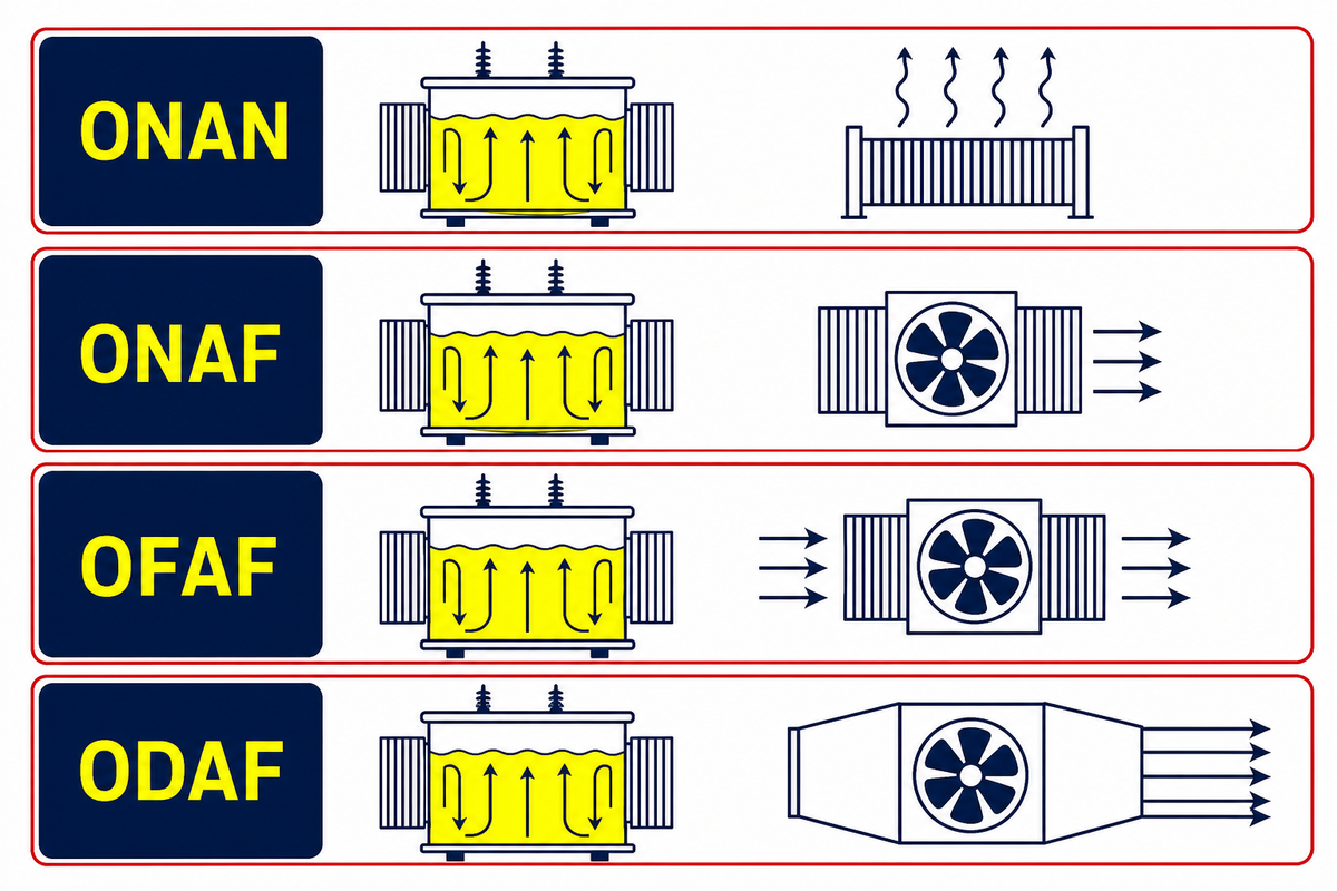
IEC four-letter cooling codes describe the internal medium and its circulation, followed by the external medium and its circulation. They describe a heat-removal arrangement. They don’t, on their own, state the temperature of the transformer, the temperature of the upper layer of oil, or permission to operate above the nameplate rating.
| Code | Internal path | External path | What remains unstated |
|---|---|---|---|
| ONAN | Oil, natural circulation | Air, natural circulation | Rating basis, ambient, rise limits, radiator state |
| ONAF | Oil, natural circulation | Air, forced by fans | Fan stages, controls, approved ratings, duty |
| OFAF | Oil, forced but not directed through windings | Air, forced | Pump/fan availability, flow design, thermal evidence |
| ODAF | Oil, forced and directed through designed paths | Air, forced | Duct layout, controls, tested temperature rise, load case |
For ONAN cooling, buoyancy drives oil and air movement. ONAF adds fan-assisted external airflow. OFAF adds forced oil circulation, while ODAF directs forced oil through intended winding passages. The existence of fans or pumps isn’t a generic percentage increase. IEEE C57.91-2025 treats loading scenario, ambient temperature, altitude, cooling technique, auxiliary equipment, and thermal consequences together. The mismatch risk appears when a buyer treats a cooling-code change as an automatic capacity increase, because a 100% nameplate loading case still depends on the stated ambient, altitude, controls, and approved cooling stage. The rated capacity of the transformer and each approved cooling stage must come from unit-specific evidence.
6. Conservator and Hermetically Sealed Systems: Two Common Expansion Arrangements
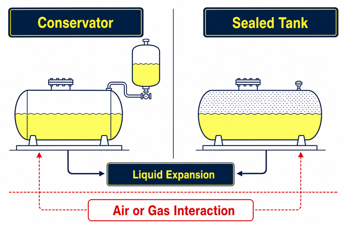
Liquid volume changes with temperature. Every preservation system must accommodate that movement while managing the liquid’s contact with air or another gas. Conservator and sealed-tank arrangements are common, but they aren’t the complete taxonomy.
| Arrangement | How expansion is handled | Visible interface | Limitation |
|---|---|---|---|
| Conservator | Liquid moves between the main tank and auxiliary vessel | Conservator, level indication, and often a breather or membrane system | Accessory names do not reveal membrane condition, air path, or owner procedure. |
| Sealed tank | A gas space or flexible/corrugated tank accommodates volume change within a sealed boundary | Tank movement, pressure/vacuum protection, level or pressure indication as designed | “Sealed” does not mean pressure-free or inspection-free. |
The transformer breather belongs to the air-exchange path on a breathing conservator system. It is commonly intended to limit moisture in the air entering that path. Sealed-conservator systems may add a membrane; other designs can use a positive-pressure gas blanket, a sealed main-tank gas space, or a free-breathing arrangement. CIGRE notes that no single standard code, comparable to the cooling-code system, differentiates all major preservation types.
This context matters beyond hardware identification because gas can be retained or lost differently. It also explains why hermetically sealed transformer construction should be reviewed with the actual tank design, accessories, pressure basis, access needs, and owner procedures—not by footprint alone.
7. Where Transformer Losses Become Heat
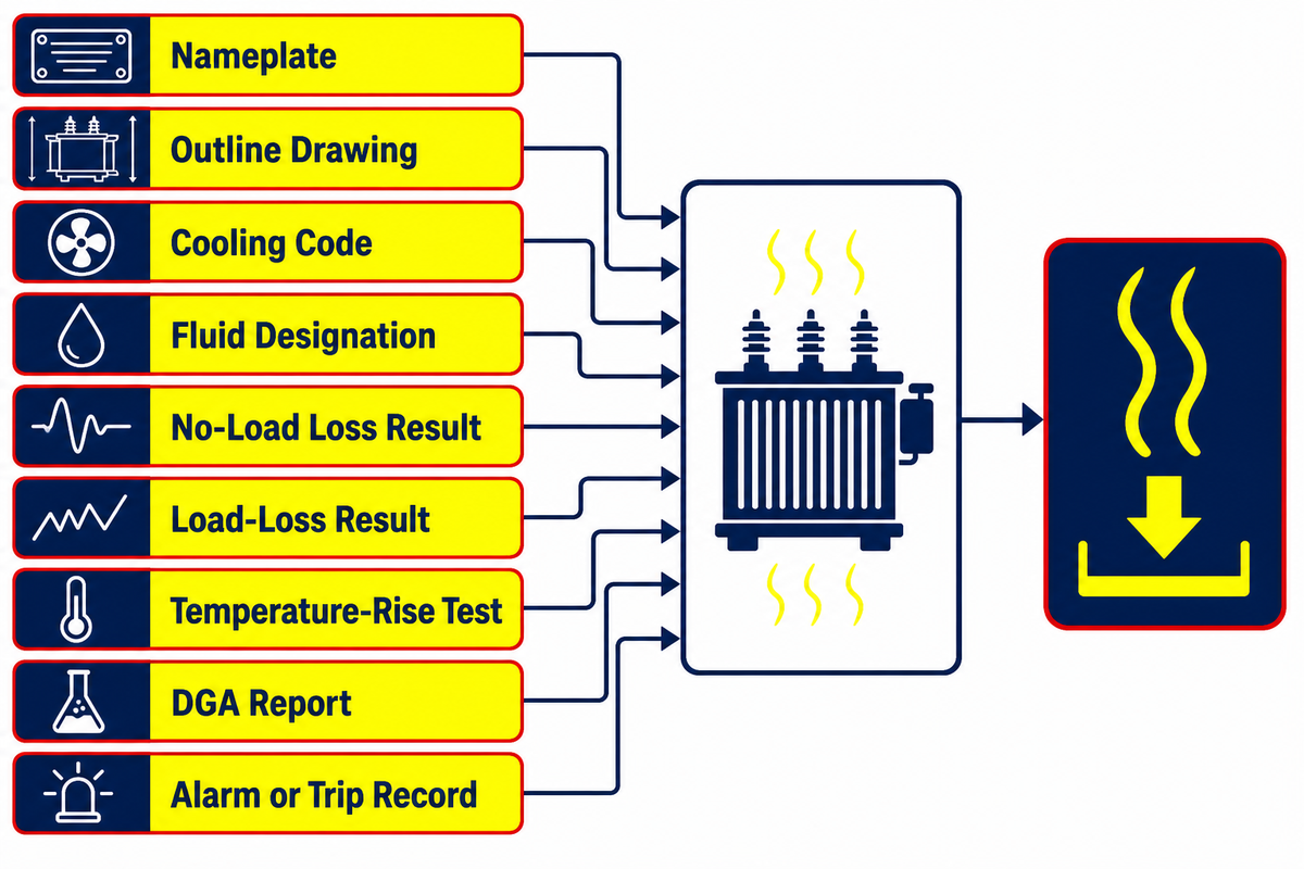
A real transformer has both no-load loss and load loss. No-load loss is associated mainly with energizing the magnetic core and exists whenever the unit is energized at the stated voltage and frequency. Load loss is associated mainly with current in the transformer winding and stray effects. Both enter the thermal path, but they respond differently to operating conditions.
For a teaching example, set the rated-current load-loss share to 100 units. At 50% current, a simplified current-squared relationship gives 100 × 0.50² = 25 units. That doesn’t mean total transformer loss is 25% at half load: the no-load component remains, stray components and temperatures matter, and the example isn’t annual-energy math or product data. The risk is a mismatch between the teaching ratio and the actual application because a test report separates measured loss quantities under stated conditions.
This is why a single efficiency value can’t describe every duty. The loss schedule, stated test basis, loading profile, ambient conditions, cooling availability, and temperature-rise evidence need to match. IEEE C57.12.90-2021 covers methods including winding resistance, ratio and phase relation, no-load and load losses, dielectric tests, temperature rise, short circuit, and sound for applicable liquid-immersed equipment. IEC 60076-2 separately addresses temperature rise for liquid-immersed transformers. A standard scope says what the document covers; the unit’s records show what was actually tested.
Nine records, nine different questions
This evidence handoff table keeps commonly requested records in their proper lanes. Each item can support one decision, but none substitutes for the complete unit file.
| Record or signal | What it answers | What it cannot prove alone |
|---|---|---|
| Nameplate | Declared identity and ratings | Current internal condition |
| Outline drawing | External arrangement and interfaces | Measured electrical performance |
| Cooling code | Fluid and air circulation arrangement | Automatic overload permission |
| Fluid designation | Specified insulating-liquid family | Compatibility or destination approval |
| No-load loss result | Measured loss under the stated test basis | Annual energy use for every load profile |
| Load-loss result | Measured load-related loss on the test basis | Every field temperature outcome |
| Temperature-rise test | Thermal result under stated conditions | Unlimited loading in a different ambient |
| DGA report | Gas measurements and interpretation inputs | A diagnosis without history and context |
| Alarm or trip record | What the monitoring system recorded | Root cause without corroborating evidence |
Oil temperature also doesn’t equal winding hot-spot temperature. Top-oil indication, ambient temperature, fan status, load history, and a thermal model answer different questions. Interpreting them together requires engineering analysis; one thermometer alone cannot establish winding hot-spot temperature.
8. Oil-Immersed vs Dry-Type Transformers: What Changes Physically?

The fundamental difference between oil-immersed and dry-type construction lies in the insulation system and the environment around the active part. In liquid-filled designs, the windings and core are immersed in an approved insulating fluid. In a dry-type transformer, solid insulation and surrounding airflow or another non-liquid cooling path serve those roles.
Oil-immersed
The liquid is part of both the dielectric and thermal paths. Site documentation may therefore address containment, fluid-maintenance accessories, condition reports, and requirements specific to the selected liquid.
Dry-type
Solid insulation and the airflow path shape the thermal design, while the enclosure controls environmental exposure. Room ventilation, contaminants, maintenance access, enclosure rating, sound limits, and fire strategy remain project inputs.
What are the key differences between oil-immersed and dry transformers?
Oil-immersed and dry-type transformers differ in cooling path, dielectric medium, enclosure, condition evidence, and site interfaces. Neither is universally better. Duty, indoor or outdoor location, fire strategy, environmental controls, containment, altitude, ambient, sound limits, access, maintenance capability, destination rules, and required documentation can change the result. Even within oil-filled transformers, mineral and ester fluids shouldn’t be collapsed into one property set. Compare the named duty, installation, liquid, enclosure, and evidence requirements rather than assigning a generic score.
Use this dry-type transformer construction page when that physical route needs separate commercial review. This guide doesn’t assign High, Medium, or Low scores because those labels mask the project-specific conditions that decide the comparison.
9. Condition Signals That Need Qualified Review
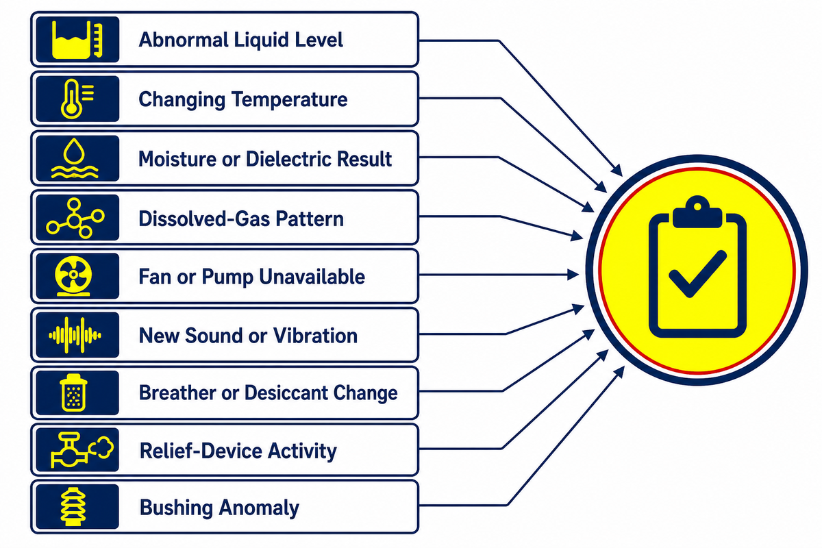
Condition evidence can include current and historical liquid level, ambient and oil-temperature trends, moisture indicators, dielectric-test results, and dissolved-gas analysis reports. None of these is a diagnosis by itself. Preserve trip conditions, load and ambient data, alarm states, sampling and laboratory context, chain of custody, preservation design, equipment history, and relevant manufacturer instructions.
| Signal type | Affected path | Possible meaning | Evidence needed next | Decision owner |
|---|---|---|---|---|
| Abnormal liquid level or visible leak | Dielectric, thermal, preservation | Loss of liquid, gauge issue, temperature-related movement, or tank-system change | Time, load, temperature, tank design, alarms, inspection record | Owner’s qualified electrical/asset team |
| High or changing temperature | Thermal | Load, ambient, cooling-stage, flow, indication, or internal condition change | Load profile, ambient, oil and winding indicators, fan/pump status, trend | Operations plus transformer specialist |
| Moisture or dielectric result | Dielectric, preservation | Fluid/paper equilibrium, handling, contamination, aging, or ingress question | Temperature, method, trend, oil-paper context, lab quality, preservation system | Asset engineer and qualified laboratory |
| Dissolved-gas pattern | Dielectric, thermal | Possible thermal/electrical activity, gas retention/loss, or sample issue | Verified sample quality, trend, load events, preservation type, related tests | Qualified DGA/transformer specialist |
| Fan or pump stage unavailable | Thermal | Cooling-path or control availability question | Approved rating stage, indication, control event, load and ambient | Operations and controls/transformer specialist |
| New sound or vibration | Magnetic, mechanical, thermal | Supply, load, mounting, cooling equipment, or internal change | Event time, voltage/load context, recordings, protection activity, inspection | Owner’s qualified electrical team |
| Breather or desiccant change | Preservation | Air-path, moisture, loading-cycle, or accessory question | Exact preservation design, owner criteria, ambient history and inspection record | Maintenance planner or transformer specialist |
| Relief-device activity | Preservation, pressure boundary | Pressure event, indication fault, or internal condition question | Protection/event logs, tank design, pressure evidence and qualified inspection | Asset owner and transformer specialist |
| Bushing surface or thermal anomaly | Dielectric, current path | Contamination, connection, loading, indication, or bushing-condition question | Comparable phase data, load, weather, inspection and applicable test record | Qualified electrical/asset team |
IEEE C57.104-2019 explicitly addresses DGA quality verification, limitations, interpretation, and norms. CIGRE research also shows that preservation type can affect fault-gas retention, so “sealed versus breathing” can’t be guessed from a single oxygen/nitrogen result. If you need the acceptance, commissioning, serviceability, and repair evidence sequence, use the separate guide to the nine evidence gates for an oil-immersed power transformer.
10. Standards Scope and the 2029 U.S. Efficiency Date
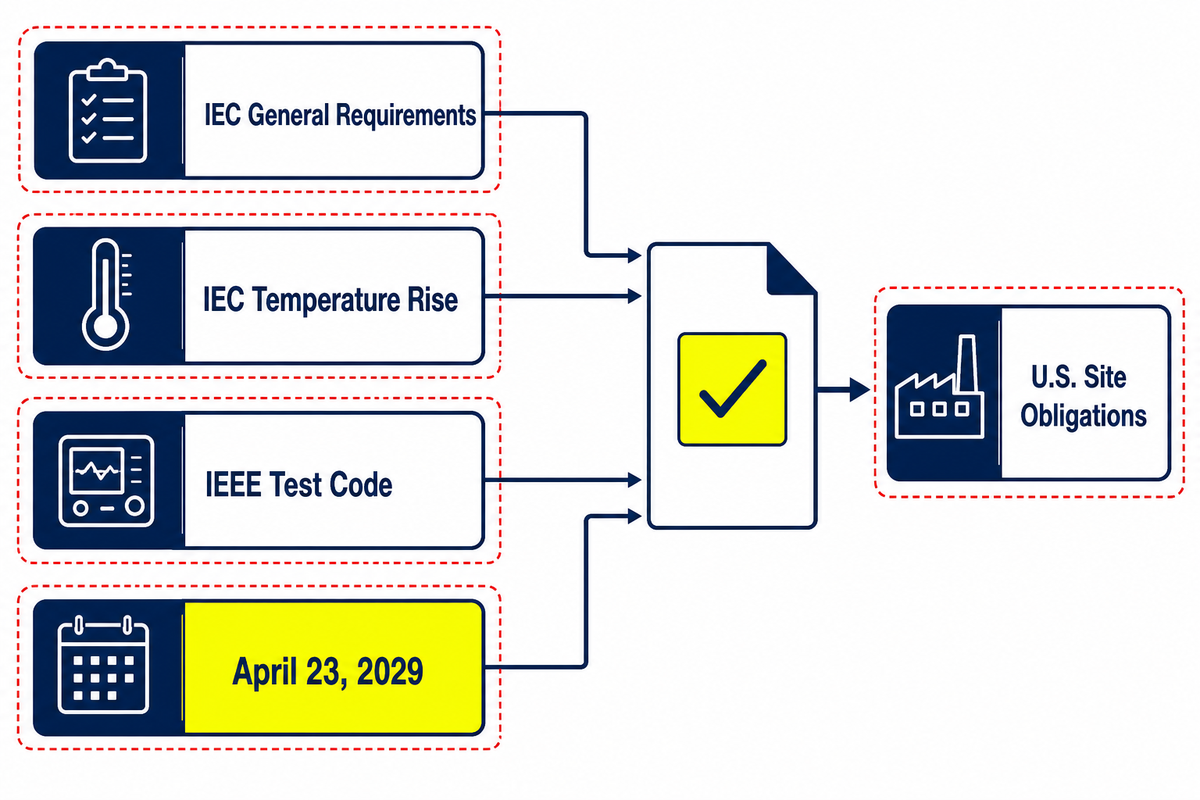
Standards, test records, market rules, and certifications answer different questions. IEC 60076-1:2011 states general requirements for power transformers. IEC 60076-2:2011 applies to liquid-immersed transformers and covers cooling identification, temperature-rise limits, and temperature-rise testing. IEEE C57.12.90-2021 is a test code for applicable liquid-immersed distribution, power, and regulating transformers. Citing one of these documents does not prove that a particular unit passed a requested test or holds a market approval.
On and after April 23, 2029, U.S. DOE-covered distribution transformers must meet the standards established in the April 2024 final rule. That timing affects product and documentation planning, but it doesn’t apply to every international power-transformer type or configuration.
U.S. site obligations are separate again. EPA guidance includes oil-filled operational equipment such as transformers in certain SPCC facility-capacity calculations, while containers below 55 gallons are excluded from that calculation. EPA also maintains registration requirements and an active database for PCB transformers. These are facility and legacy-equipment questions, not properties of every new oil-immersed unit; applicability belongs with the owner’s environmental and legal review.
The evidence handoff
Use the name to read the four paths. Use the plate and drawings to read the unit. Use test records to read the measured results. Use the standard edition and destination standard to read the standard’s scope. None of those layers substitutes for the others.
If your next task is to turn that understanding into voltage, rating, cooling, fluid, accessories, tests, and project documentation, review Toplit’s oil-immersed transformer solutions and published ratings.
Oil-Immersed Transformer FAQs
What is transformer oil used for?
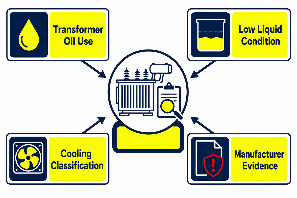
Transformer oil forms part of the dielectric system and carries heat from the active assembly toward the tank and radiators. Its limits depend on the unit design, liquid family, materials, cooling arrangement, operating conditions, and applicable instructions, not the name alone.
What happens if a transformer runs out of oil?
Abnormally low liquid can affect dielectric coverage and heat removal. The consequences depend on tank design, level, energization, temperature history, and the source of the loss. Preserve the observation, follow the owner’s procedures, and obtain qualified review before taking action.
How are oil-immersed transformers classified by cooling method?
Four-letter codes identify the internal medium and flow method, then the external medium and flow method. ONAN, ONAF, OFAF, and ODAF describe discrete heat-removal layouts, but the code must be interpreted with the nameplate, ambient basis, controls, applicable standard, and accepted loading instructions.
Who makes oil-filled transformers?
Many global and regional transformer manufacturers build them. A phrase such as “leading transformer manufacturer” is marketing language, not evidence of fit. Compare the exact design scope, test records, quality system, references, and project documentation. Ask whether the stated ratings, cooling arrangement, fluid, accessories, standards edition, destination requirements, and inspection plan all refer to the offered unit. Confirm which records are standard deliverables and which require agreement. Toplit’s company and transformer factory background is available separately.
We separated physical-system education from product selection, checked current public scopes from IEC, IEEE, DOE, EPA, OSHA, and CIGRE, and rejected unsupported universal temperature, overload, life, and fluid claims. Toplit’s first-party pages are used only for company and published-product context.
Have a Defined Transformer Duty?
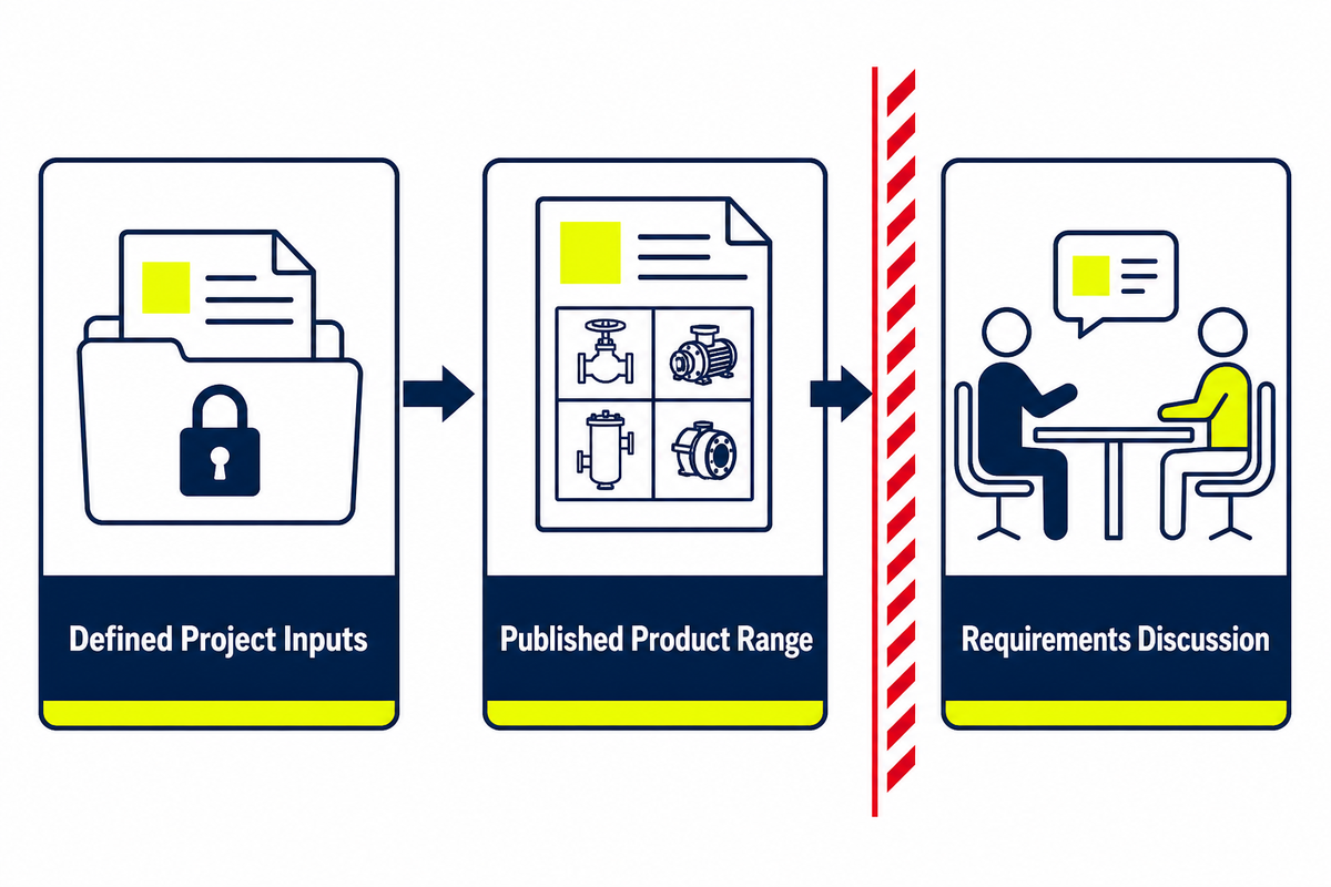
Bring the voltage, rated capacity, frequency, load profile, ambient and altitude, preferred cooling and fluid, destination standard, accessories, and required test documents. Toplit can then relate those project inputs to its published product range without turning a construction label into an unsupported selection.
References & Sources
- IEC 60076-1:2011, Power transformers, general scope
- IEC 60076-2:2011, Temperature rise for liquid-immersed transformers
- IEEE C57.12.90-2021 — Test code scope
- IEEE C57.91-2025 — Loading guide scope
- IEEE C57.104-2019 — DGA interpretation scope and limitations
- U.S. DOE — Distribution transformer definitions, test procedure, and compliance timing
- CIGRE — Dielectric performance of insulating liquids
- CIGRE — Oil preservation types and DGA context
- OSHA 1910.269 — Electric power generation, transmission, and distribution
- U.S. EPA — SPCC guidance for oil-filled operational equipment
- U.S. EPA — PCB transformer registration
![Pad-Mounted Transformer: How It Works [2026 Guide]](https://toplit-transformer.com/wp-content/uploads/2026/08/pad-mounted-transformer-guide-featured-150x150.png)

![Single Phase Pad Mounted Transformer Guide [2026]](https://toplit-transformer.com/wp-content/uploads/2026/08/single-phase-pad-mounted-transformer-guide-featured-1-150x150.png)