Get in touch with Talite Transformer Co., Ltd Company

Updated August 2026
A power transformer transfers alternating-current electrical energy between circuits through electromagnetic induction; in a power system, it commonly raises voltage near generation, lowers it at grid substations, and keeps the same frequency while changing the voltage and current relationship. This guide explains the category, the evidence behind its key ratings, and the point where a general explanation must give way to project engineering.
This article combines public regulatory and standards scope with the currently published Talite parent-category material; it is an educational reference, not a design approval, operating instruction, or statement of product certification.
What Is a Power Transformer, and Where Does It Fit in the Grid?
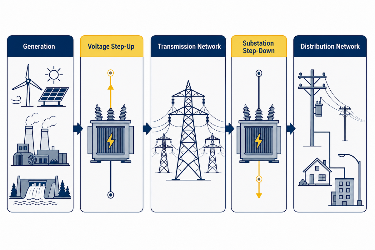
A power transformer is a static device that transfers AC power between windings by means of a changing magnetic field; its grid purpose is to place electrical energy at a useful voltage level for a particular part of the network, and it can support step-up or step-down roles without changing frequency.
According to the U.S. Department of Energy, transformers exchange power between systems at different voltages in the transmission and distribution path. Electric power moves from generating stations into power networks, while large power transformers at selected boundaries support bulk power transfer and efficient long-distance power transmission. From there, the transmission of electric power reaches substations, where electrical power distribution reduces the power level for local networks; some sources call that last stage electric power distribution.
One familiar grid sequence is power plants, a step-up transformer, high-voltage power transmission, a substation transformer, and downstream power distribution. Raising voltage for a given power transfer reduces current flow, which can reduce conductor loss; lowering voltage later makes power suitable for the next network layer. Where a transformer is used does not define every construction choice, so system role is more useful than a universal catalogue label.
A distribution transformer usually serves the downstream delivery network closer to loads, while instrument transformers serve measurement or protection functions and small consumer converters serve power supplies rather than bulk grid duty. Across markets, the labels overlap, so a real specification has to state duty, voltage, phase, insulation, cooling, and applicable requirements instead of relying on the name alone; for a narrower voltage-class discussion, see this 110 kV power transformer guide.
System boundary: generation → voltage step-up → transmission network → substation step-down → distribution network. A transformer sits at a voltage boundary; it does not create electrical energy or decide how a network should be rated.
How Does a Power Transformer Work?
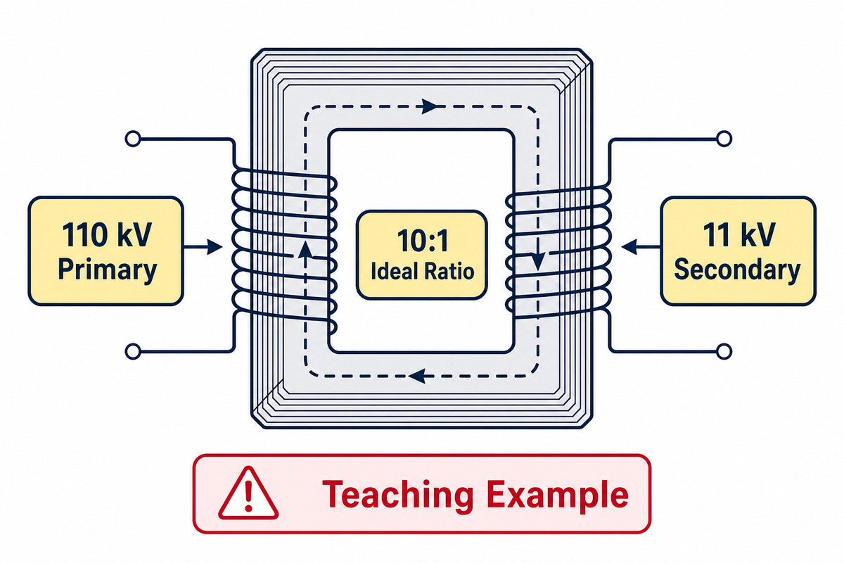
Power transformers work because alternating current in a primary winding creates changing flux in a transformer core; inside the magnetic circuit, the core provides a path that links the secondary winding. Faraday’s law then produces an induced voltage at the secondary terminals, while many designs keep the windings electrically separate and couple their energy transfer through the magnetic field.
In an ideal description, the voltage ratio follows the turns ratio:
Vprimary / Vsecondary = Nprimary / Nsecondary
Turns ratio and the ideal voltage relationship
Take an ideal 110 kV / 11 kV example: dividing 110 by 11 gives a 10:1 voltage ratio, so the ideal winding turns ratio is 10:1. If the primary winding has 10 turns for every one turn on the secondary winding, the secondary voltage is one tenth of the primary voltage under the ideal assumptions; current changes in the opposite direction when power is approximately conserved.
This is a transparent teaching calculation, not product data, a fault-study result, or sizing guidance. It assumes sinusoidal AC, an ideal core, no winding resistance, no leakage reactance, no excitation demand, and no voltage drop. A real unit cannot be selected from its turns ratio alone.
Why real behavior has more variables
Real transformer operation includes magnetizing current, winding resistance, leakage reactance, excitation behavior, transformer losses, impedance, and thermal limits. These affect voltage regulation, heat, current capability, and the way a unit interacts with the electrical system. IEEE’s liquid-immersed transformer test-code record lists ratio, resistance, no-load/excitation, impedance/load-loss, dielectric, temperature, short-circuit, and sound categories, which is a useful reminder that one equation does not describe the whole machine. The relevant test framework is IEEE C57.12.90-2021.
In power engineering, input power and output power are not identical because energy loss appears in the core, windings, and auxiliaries. Transformer energy accounting therefore separates power loss by operating condition. The equations explain transformer fundamentals, while measured electrical power evidence describes the real unit.
Which Components Control Performance and Reliability?
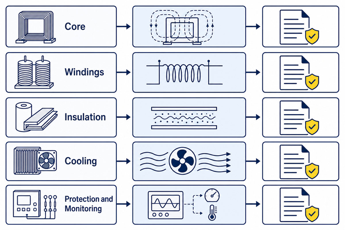
The components of a power transformer do not form one interchangeable block: the transformer core, transformer windings, insulation system, tank, bushings, tap changer, cooling equipment, and transformer protection each carry a different physical job. Reading them as a component-to-consequence chain helps a reader ask for evidence without making a diagnosis from appearance alone.
| Component | Primary function | What changes when its condition degrades | Evidence a qualified team reviews |
|---|---|---|---|
| Transformer core | Provides the magnetic circuit for induced voltage. | Excitation behavior and core-loss patterns may depart from the expected condition. | Test records, excitation evidence, operating history, and construction documentation. |
| Transformer windings | Carry current and establish the voltage ratio. | Resistance, insulation condition, mechanical restraint, and heat exposure can affect performance. | Ratio and resistance records, dielectric evidence, event history, and comparison trends. |
| Transformer insulation | Separates energized parts and withstands electrical and thermal stress. | Moisture, heat, contamination, or aging can change dielectric condition. | Approved test method, insulation records, condition history, and applicable procedure. |
| Transformer tank and fluid system | Encloses liquid-immersed equipment and supports heat transfer where applicable. | Leaks, corrosion, fluid condition, or cooling defects can affect containment and thermal performance. | Visual condition, fluid records, thermal history, and owner procedures. |
| Bushings and tap changer | Provide external connections and permitted voltage adjustment functions. | Connection, insulation, contact, or mechanism concerns can affect reliability and regulation. | Inspection evidence, operating records, test evidence, and protection-event history. |
| Cooling equipment | Moves heat from active parts to the surrounding environment. | Reduced cooling can change the unit’s thermal behavior. | Temperatures, alarms, fan or pump records, and inspection history. |
| Protection devices | Detect defined abnormal conditions and initiate the designed response. | Missing or incorrect operation can increase event consequences. | Settings, coordination records, event files, and functional checks. |
| Monitoring instruments | Provide operating and condition measurements. | Bad data can hide a trend or create a false concern. | Calibration status, trends, alarm history, and cross-checked readings. |
| External terminals and connectors | Carry current across the equipment boundary. | Connection condition can affect heating and electrical integrity. | Approved inspection evidence, thermal trends, and maintenance records. |
Even so, this table does not turn an observation into a repair instruction. For example, a stain near a transformer tank, a changed temperature pattern, or an unexpected protection event is evidence to route through the owner procedure and qualified review. That chain helps distinguish transformer faults from protection events or instrument issues; public readers should not infer transformer failure or the cause of failure of power transformers from one symptom.
What Are the Main Types of Power Transformers?
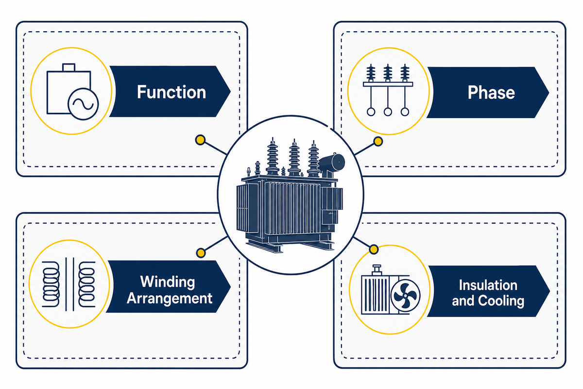
There is no single technically complete list of power transformer types because the classification axis changes with the question; function, phase, winding arrangement, insulation and cooling, and network role all describe different facts. A clear article names the axis before grouping equipment, so an educational list is not mistaken for a product range.
Function, phase, and winding arrangement
By function, a step-up transformer raises voltage and a step-down transformer lowers it. An autotransformer uses a shared winding arrangement for part of the voltage transformation; isolation transformers emphasize separated windings; a grounding transformer and other special-purpose units meet more specific system functions. By contrast, a balun transformer belongs to radio-frequency or signal taxonomy rather than the usual grid-duty grouping. Single-phase and three-phase descriptions state phase arrangement, not a quality ranking. These are categories for understanding a power system, not selection instructions.
Insulation and cooling scope
Oil-immersed designs use transformer oil as part of the insulation and cooling system. Large oil-filled power transformers and smaller liquid-filled units still need design-specific evidence; the label does not establish a rating. Dry-type designs use different insulation and transformer cooling arrangements. Neither label settles every application question because environment, enclosure, duty, voltage class, fire rules, ventilation, and the approved specification still matter. Readers seeking that narrower category distinction can review the site pages on oil-immersed transformers and dry-type transformers.
Power transformer versus distribution transformer
The distinction is usually about grid role and operating duty rather than one worldwide numeric cutoff. Power transformers are commonly associated with transmission or high-capacity substation duties; distribution transformers serve downstream delivery. The applicable standard, utility practice, local regulations, and project documents establish the real boundary. This is why a four-type list is useful only when it first says whether it is grouping by function, construction, or application.
How to Read Power Transformer Ratings Without Treating Them as a Shopping List
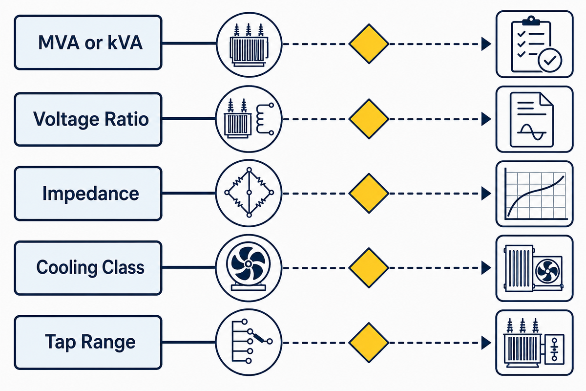
On a nameplate, separate fields make separate engineering statements. MVA or kVA names a power capacity under stated conditions; voltage ratio identifies intended winding voltages; frequency, impedance, cooling class, and tap range answer other questions. Instead of treating one field as a recommendation, identify the evidence needed before a system decision.
What Does an MVA Rating State, and What Does It Leave Unstated?
Under stated rating conditions, an MVA rating expresses apparent-power capability. It does not, by itself, establish the correct unit for a particular load profile, fault duty, voltage regulation target, environment, protection arrangement, governing standard, or the purchaser’s specific declared duty.
In a three-phase balanced system, apparent power follows S = √3 × VLL × IL; in a single-phase system, S = V × I. These relationships identify how voltage and current connect to apparent power, but the system assumptions and approved documents still control project selection.
| Rating field | Physical meaning | System consequence | Evidence needed before a decision |
|---|---|---|---|
| MVA or kVA | Apparent power at stated conditions. | Relates voltage and current capability. | Load profile, duty, ambient conditions, and approved capacity basis. |
| Voltage ratio | Nominal primary and secondary voltage relationship. | Connects transformer windings to network voltage levels. | System one-line, source variation, secondary requirements, and regulation study. |
| Frequency and phase | Electrical supply characteristics. | Influence magnetic operation and network compatibility. | Declared system frequency, phase arrangement, and governing specification. |
| Impedance | Internal voltage-drop and fault-current characteristic. | Affects voltage regulation and short-circuit study results. | Network study, protection coordination, source data, and approved fault-duty basis. |
| Cooling class | Declared heat-removal arrangement. | Links loading context to temperature behavior. | Ambient, installation setting, cooling evidence, and applicable loading guide. |
| Tap range | Permitted voltage adjustment range under defined conditions. | Can affect regulation and operating flexibility. | Voltage-variation study, tap-control requirements, and operating philosophy. |
| Insulation level | Declared dielectric withstand basis. | Connects equipment insulation to system stress and coordination. | System insulation study, applicable standard, altitude, and test requirements. |
| Test classification | Names the agreed routine, type, or special test context. | Defines which evidence should exist for the order. | Purchaser specification, approved test plan, records, and acceptance criteria. |
| Interfaces and protection | Defines connections, sensing, alarms, and protective functions. | Affects integration, coordination, and operating response. | One-line diagram, interface schedule, protection study, and approved drawings. |
IEEE’s general-requirements records separate liquid-immersed and dry-type scopes. Within its covered mineral-oil-immersed scope, the loading guide identifies insulation, temperature, ambient, altitude, cooling, and scenario as relevant context. See IEEE C57.12.00-2021, IEEE C57.12.01-2020, and IEEE C57.91-2025. A rating is evidence, not an approval. System studies and approved specifications govern the final project decision.
Where Power Transformer Losses Come From, and Why Load Shape Matters
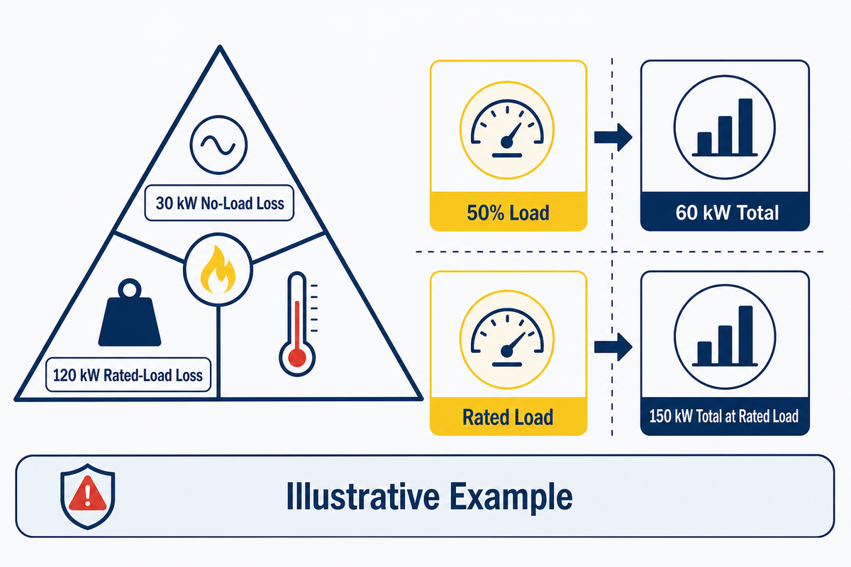
Transformer losses are not one fixed percentage. No-load loss is associated with energizing the core and remains present while the transformer is energized. Load loss rises as winding current rises, and auxiliary consumption may add to the energy picture where cooling equipment or other auxiliaries are in service; consequently, the load profile matters as much as a headline efficiency figure.
Loss-Load-Heat Triangle
Think of the relationship as a three-corner check: loss turns into heat, while load changes the current-dependent portion of loss. Heat then has to be understood alongside ambient conditions, cooling arrangement, insulation, and operating history; if any corner is removed, the remaining number can look more certain than it is.
| Corner | Question it answers | What it cannot establish alone |
|---|---|---|
| Loss | What energy is dissipated under a defined test or duty condition? | Whole-life energy exposure across a changing load profile. |
| Load | How much current-dependent loss is present at this operating point? | Temperature outcome without ambient and cooling context. |
| Heat | What thermal condition needs review under stated conditions? | A universal loading allowance or maintenance action. |
Why can the same efficiency number hide different operating costs?
DOE test-procedure material distinguishes no-load and load losses and displays a squared-load adjustment for the load-loss portion. Consider an illustrative transformer with 30 kW no-load loss and 120 kW rated-load loss. At 50% per-unit load, the simplified load-loss calculation is 120 kW × (0.50)2 = 30 kW. Add the 30 kW no-load loss and the illustrative total is 60 kW while energized at that load point.
At rated load in the same illustration, the load-loss term is 120 kW × (1.00)2 = 120 kW, so the total becomes 150 kW. That difference comes from the current-squared term, not from a change in the stated no-load loss. These figures are a teaching example only, not Talite product data, a performance guarantee, an annual-energy forecast, or sizing guidance. DOE’s distribution-transformer test-procedure material describes the underlying physical relationship within its own regulatory scope, which should not be extended to every power transformer.
Temperature and insulation context still matter. IEEE C57.91-2025 addresses loading consequences for covered mineral-oil-immersed units in relation to insulation, ambient, altitude, cooling, and operating scenario. It does not provide a public universal overload rule for every design.
What Information Is Needed Before a Transformer Can Be Evaluated?
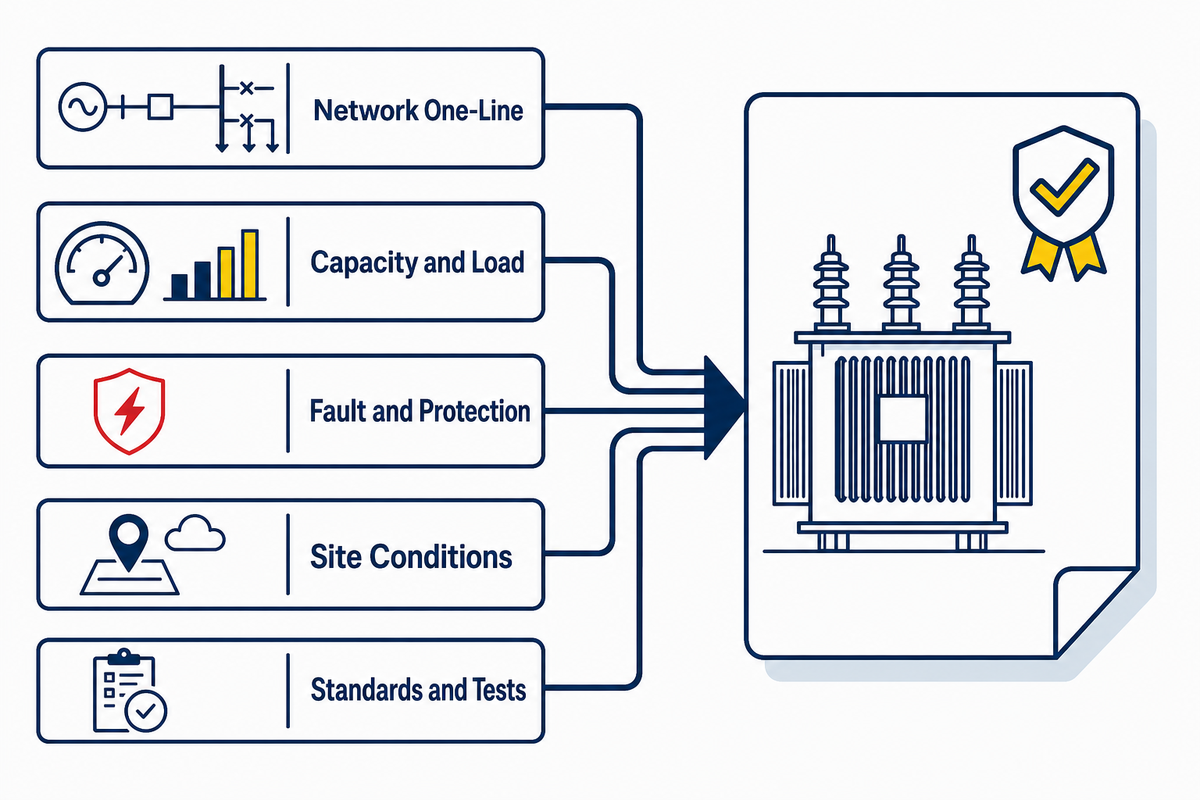
Start a sound project conversation with the network and duty, not a catalogue filter. Across power transformer applications, the required inputs define where equipment sits, what voltage it interfaces with, how the load behaves, which studies exist, and what verification documents apply; they do not by themselves select a model.
On the one-line, power sources and power flow appear through power transmission or distribution stages. Transformer specifications then bind those system facts to declared interfaces, studies, tests, and document requirements.
- Network one-line, primary and secondary voltage levels, frequency, phase, and grounding context.
- Declared capacity basis, load profile, expected duty, future changes already approved, and power-quality considerations.
- Available short-circuit and source information, impedance or regulation requirements, and protection coordination context.
- Ambient, altitude, location, enclosure, cooling, insulation, transport, and installation constraints.
- Applicable standards, jurisdictional rules, purchaser specification, test requirements, and document-control expectations.
These inputs expose missing information early. For example, an MVA figure without the voltage, fault-study, cooling, and environment context answers only one part of the engineering question. Readers who have those inputs and need a project-specific review can move to power transformer solutions for project specifications. That commercial page is the handoff for project evidence and proposal work; this guide does not replace it.
What Do IEC 60076 and IEEE C57 Standards Actually Cover?
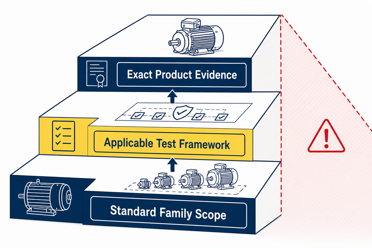
IEC 60076 and IEEE C57 are standard families, not blanket product labels. Their official records describe defined scope, edition, exclusions, and in some cases test-method categories. Citing one family can show that a standard exists and may be relevant; it cannot by itself prove a named unit’s certification, a supplier’s capability, or completed order evidence.
| Reference | Public scope signal | What still needs project evidence |
|---|---|---|
| IEC 60076-1:2011, Edition 3.0 | General scope for covered single- and three-phase power transformers and autotransformers, subject to exclusions. | Applicable clauses, equipment boundary, edition status for the order, and test evidence. |
| IEC 60076-11:2018, Edition 2.0 | Defined scope for covered dry-type power transformers, including stated voltage limits and exclusions. | Whether the actual equipment, jurisdiction, and specification fall within the scope. |
| IEEE C57.12.00-2021 | General electrical and mechanical requirements for covered liquid-immersed categories. | Model-specific conformance, exclusions, and purchaser requirements. |
| IEEE C57.12.01-2020 | General requirements for specified dry-type constructions. | Construction boundary, actual test evidence, and local adoption. |
| IEEE C57.12.90-2021 | Test-code scope including ratio, loss, dielectric, temperature, short-circuit, and sound categories. | Which tests were required, performed, witnessed, and accepted for a specific order. |
Does citing IEC 60076 prove certification?
No. It may identify a design basis or test framework, but certification is a separate claim requiring the relevant certificate, issuer, product identity, scope, validity, and ownership evidence. The linked official IEC record for IEC 60076-1 lists the 2011 publication as Edition 3.0. The record for IEC 60076-11 lists the 2018 publication as Edition 2.0 and states its dry-type scope. Neither record certifies a supplier or a product.
Regulatory dates are also bounded. DOE’s page for the 89 FR 29834 final rule says compliance with the amended standards in 10 CFR 431.196 is required for covered U.S. distribution transformers on and after April 23, 2029. That is not a worldwide rule for every power transformer. Read the defined scope at DOE’s distribution-transformer standards page.
What Should Operation and Maintenance Evidence Tell You?
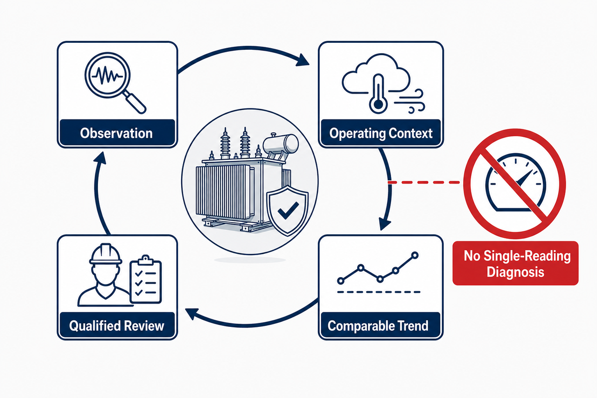
Condition evidence should help qualified personnel decide whether the current state differs from the expected state, whether a trend needs investigation, and which approved procedure governs the next step. It should not invite a public reader to perform energized work or turn one number into a universal diagnosis.
Equipment design, service conditions, transformer cooling, owner procedures, and qualified personnel determine inspection and testing intervals. The evidence must reflect how power transformers operate in their actual duty.
Visual, mechanical, thermal, and protection evidence
Condition records may include visible enclosure or transformer tank condition, bushing condition, cooling-system status, alarms, protection events, loading history, and temperature trends. A record becomes meaningful when it can be compared with prior operating context and the applicable procedure. A changed value may reflect load, ambient conditions, instrumentation, cooling state, a protection event, or an equipment concern; the evidence has to be interpreted as a set.
Transformer oil, insulation, and dissolved gas analysis
For applicable liquid-filled equipment, transformer oil and dissolved gas analysis can contribute condition evidence. IEEE C57.104’s official record covers DGA quality verification, limitations, interpretation methods, norms, fault definitions, and examples. That scope is precisely why a single laboratory result should not be treated as a stand-alone diagnosis. Sampling method, laboratory quality, equipment history, prior results, and the governing assessment method all affect the meaning.
Safety boundary for inspection and testing
Exposed energized equipment is not a do-it-yourself inspection setting. Within construction work covered by OSHA 29 CFR Part 1926 Subpart V for electric power transmission and distribution, paragraph 1926.960(b)(1)(i) states that only qualified employees may work on or with exposed energized lines or parts of equipment. Local law, site rules, equipment documentation, and owner procedures may be stricter or different. This article gives no live-work procedure, test sequence, gas threshold, fluid-handling instruction, or maintenance interval. See OSHA 29 CFR 1926.960 for the cited qualified-person boundary.
Do
- Compare condition evidence with its operating context and prior trend.
- Keep source documents, test records, and event history together.
- Route concerns through the owner procedure and qualified personnel.
Don’t
- Diagnose a transformer from one DGA or temperature reading.
- Assume a generic interval applies to every design and service duty.
- Treat public guidance as authorization for energized work.
When Does General Guidance Stop and Project Engineering Begin?
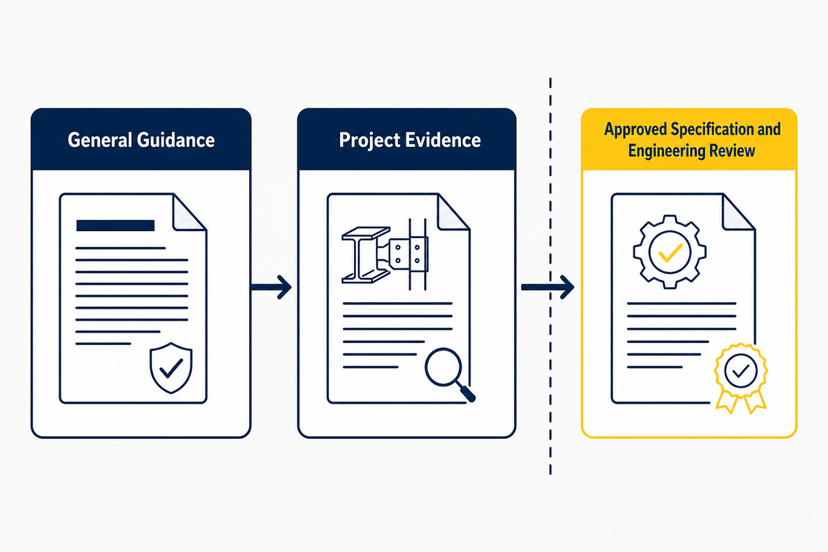
General guidance stops when a reader needs a transformer matched to a real network, duty profile, safety requirement, standard edition, or contractual test record. At that point, the next output is an approved specification and engineering review, not an online rule of thumb.
So far, this guide has explained the questions that need evidence; it has not approved a voltage ratio, rating, impedance, cooling method, protection scheme, or operating limit.
As checked on August 21, 2026, Talite’s parent-category page states a scoped series context of 5–100 MVA and 110–220 kV; this bounded first-party statement is neither a promise that every combination is available nor a recommendation for a particular project.
Bring the one-line diagram, loading and fault-study context, environmental conditions, applicable standard or purchaser requirements, and verification expectations to the project discussion. The existing commercial page is the route for project-specific power solutions. For supporting category reading, the oil-immersed power transformer guide covers that narrower topic without changing this article into a product catalogue.
Key takeaway
A power transformer rating describes a defined condition; only network evidence, applicable requirements, and qualified engineering can turn that description into a project decision.
For context on the team behind this technical review, visit About Talite. The page explains the company context; it does not replace the project evidence required for a transformer decision.
Frequently Asked Questions
What is a power transformer?
Power transformers are static electrical devices that transfer alternating-current energy between circuits through electromagnetic induction, often while changing voltage and current levels. In a grid, a power transformer commonly supports generation and transmission duties where large amounts of power move between voltage levels. Voltage class, rating, insulation, cooling, impedance, and duty still have to be defined for a real project. It does not generate energy, and its name does not prove one construction or test record.
What are the four types of transformers?
There is no universal technical list of four transformer types because classifications can be by function, phase, construction, insulation, cooling, or application. A basic functional list may include step-up, step-down, isolation, and autotransformers. A utility list may instead distinguish power, distribution, instrument, and special-purpose units. State the classification axis before using the list.
How does a power transformer work?
Alternating current in the primary winding creates changing magnetic flux in the transformer core, which induces voltage in the secondary winding. The turns ratio largely describes the ideal voltage ratio, while current changes inversely when power is approximately conserved. Real performance also depends on magnetizing current, resistance, leakage reactance, losses, impedance, and thermal limits. The output then feeds the next voltage level under the unit’s actual loading and cooling conditions.
Why are power transformers used?
Power transformers let a power grid raise voltage for bulk transfer and lower it for downstream networks while maintaining frequency. Reducing current for a given transfer can reduce conductor losses. Actual system performance still depends on loading, impedance, cooling, insulation, and the approved design basis.
How is a power transformer different from a distribution transformer?
Power transformers are generally associated with bulk transmission or high-capacity substation duty, while distribution transformers serve the downstream network closer to loads. Exact boundaries vary by standard, utility practice, and market. Role, duty cycle, and applicable specification provide a more reliable distinction than a universal cutoff. The distinction does not settle whether a unit is liquid-immersed or dry-type, three-phase or single-phase, or which voltage class it uses; those are separate classification axes. For project work, read the one-line diagram, declared duty, load profile, cooling context, and governing standard together rather than transferring a catalogue label across markets.
References & Sources
- U.S. Department of Energy, Electricity Transmission Primer, for grid voltage roles and transmission context.
- U.S. Department of Energy, Distribution Transformer Test Procedure Material, for the no-load and squared-load-loss relationship in its stated scope.
- IEC 60076-1 official publication record, for general scope and edition status.
- IEC 60076-11 official publication record, for dry-type transformer scope.
- IEEE C57.12.00-2021 official record, for general requirements in its liquid-immersed scope.
- IEEE C57.12.01-2020 official record, for general requirements in its dry-type scope.
- IEEE C57.91-2025 official record, for loading-guide scope and covered context.
- IEEE C57.12.90-2021 official record, for test-code categories.
- IEEE C57.104-2019 official record, for DGA scope and interpretation limits.
- OSHA 29 CFR 1926.960, for the qualified-person boundary in its covered context.
- Talite Power Transformer parent-category page, for the first-party series range checked on August 21, 2026.
![Pad-Mounted Transformer: How It Works [2026 Guide]](https://toplit-transformer.com/wp-content/uploads/2026/08/pad-mounted-transformer-guide-featured-150x150.png)
![Single Phase Pad Mounted Transformer Guide [2026]](https://toplit-transformer.com/wp-content/uploads/2026/08/single-phase-pad-mounted-transformer-guide-featured-1-150x150.png)