Get in touch with Talite Transformer Co., Ltd Company

Updated August 2026
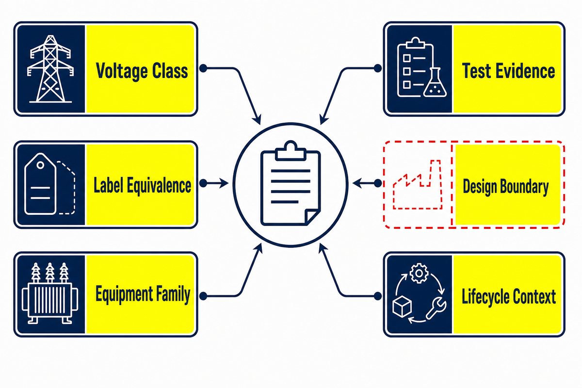
A 35kv power transformer is an electrical device that transfers AC energy between circuits at a voltage boundary associated with a 35 kV system or equipment class. That short label is not a full specification: the nameplate, system nominal voltage, rated winding voltage, insulation level, governing standard, and local regulatory scope still have to agree.
This guide helps procurement, engineering, commissioning, and operations teams interpret those records for a medium-voltage power project. It does not provide an energized-work method, relay setting, grounding design, or approval for a particular installation. Work on or near medium-voltage equipment belongs to qualified personnel following the rules and procedures that apply to the site.
Direct answer: “35 kV” is a starting label, not a selection decision. The review must connect that label to the actual voltage ratio, power rating, impedance, insulation basis, cooling state, test evidence, protection study, and operating context.
Quick orientation
- Terminology: nominal voltage, rated voltage, voltage class, and highest voltage for equipment answer different questions.
- Product family: a power transformer is not a potential transformer, even when both pages mention 35 kV.
- Evidence: a guaranteed-data sheet and a unit-specific factory report do different jobs.
- Handoff: documentation can establish readiness; only the responsible project team can approve design, installation, and energization.
What “35kV” Actually Means
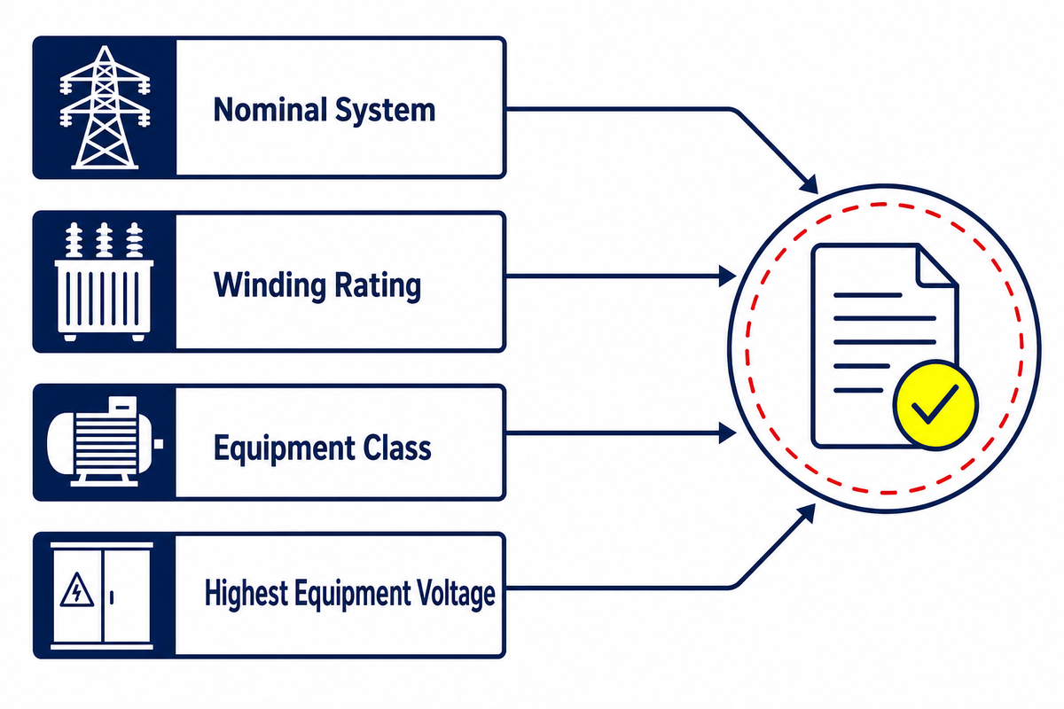
A 35 kV label can describe a nominal system, a winding rating, an equipment class, or a search shorthand. Search results may say “35kV class” or refer broadly to “35kV systems,” but neither phrase is a specification. Correct interpretation comes from the document that uses the term. Treating every instance as interchangeable can send the wrong value into insulation coordination, regulatory screening, protection studies, or a purchase specification.
In the United States, one boundary is especially easy to misread. Under 10 CFR 431.192, the Department of Energy definition describes an in-scope distribution transformer as having an input line voltage of 34.5 kV or less. It also sets conditions for output voltage, frequency, capacity, and excluded equipment categories. A transformer is not inside or outside that regulatory definition merely because a sales page says “35 kV.”
| Label | Question it answers | Where to verify it | Common error |
|---|---|---|---|
| Nominal system voltage | How the network is identified | Utility data and approved single-line diagram | Copying it directly into every equipment field |
| Rated winding voltage | Which terminal voltage the winding is designed around | Nameplate, guaranteed data, and drawings | Ignoring taps and the stated ratio |
| Equipment or insulation class | Which insulation-coordination framework applies | Project standard and insulation data | Reading “class” as the operating voltage |
| Highest voltage for equipment | Which equipment-level ceiling frames an IEC scope | Applicable IEC standard and data sheet | Assuming it equals nominal voltage |
IEC uses its own scope language. For example, the public scope of IEC 60076-11:2018 covers dry-type power transformers with highest voltage for equipment up to and including 72.5 kV, with at least one winding above 1.1 kV. That scope statement does not convert a 35 kV nameplate into a universal system classification; it tells you which dry-type standard may be relevant.
Readers who have moved from terminology into project-specific construction and configuration can review Toplit’s 35kV power transformer options. Commercial specification belongs on that product page; this article remains the evidence guide.
Power, Distribution, and Potential Transformers Are Different Families
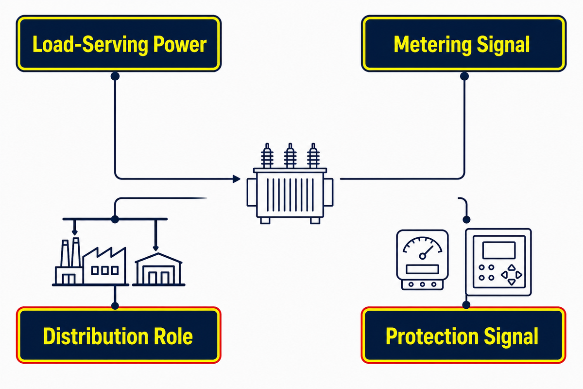
An electrical transformer transfers electric power through electromagnetic induction. In a power distribution role, a power transformer changes voltage and current levels so the connected distribution network receives its intended power supply. Engineers may call that function voltage transformation or voltage conversion. A potential or voltage transformer instead supplies a scaled signal for measurement or protection. “Distribution transformer” may describe a grid role, but U.S. efficiency law also uses it as a narrower defined category.
This distinction matters because a search for “35 kV transformer” can return a 35 kV potential transformer beside load-serving power transformers. Sharing a voltage phrase does not mean sharing an electrical job. IEC 60076-11 explicitly excludes instrument transformers from its dry-type power-transformer scope, and IEEE C57.12.90-2021 excludes instrument transformers from its liquid-immersed power-transformer test-code scope.
Family check: ask what the unit transfers and what its secondary circuit feeds. Load-serving transformers and metering/protection transformers need different data, test frameworks, and acceptance logic even when both mention the same primary voltage.
Another source of confusion is the word “power.” IEC and IEEE use power-transformer scope broadly, while a project team may casually reserve “power transformer” for larger substation units. A three-phase transformer may be written as “three phase” in one data source and “three-phase” in another; punctuation does not settle the connection or duty. Safe specifications name the duty, voltage ratio, phases, frequency, power rating, cooling arrangement, insulation basis, and invoked standards rather than assuming everyone uses the category label the same way. For the wider equipment-family context, see Toplit’s power transformer overview.
Nameplate-to-Study Decoder
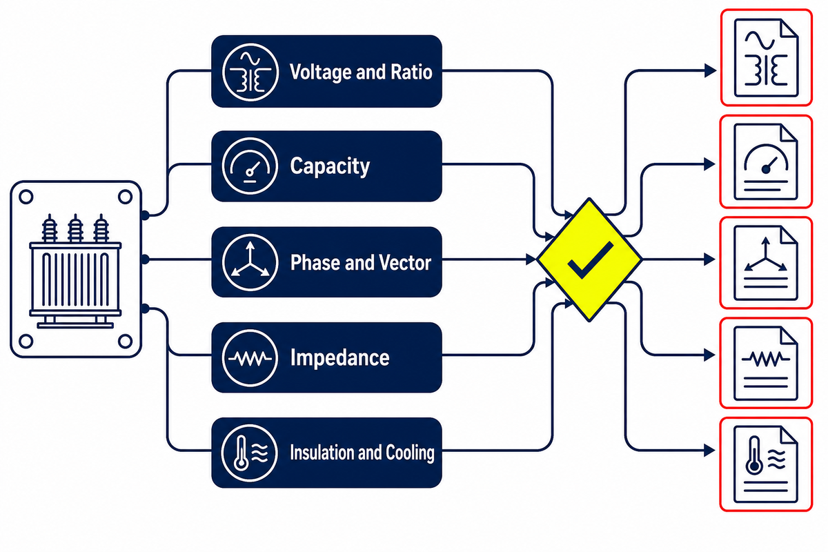
A transformer nameplate is a compact interface between the manufactured unit and the power-system studies around it. Each field changes a different decision, and no field approves the transformer alone. The review should reconcile the nameplate, guaranteed-data sheet, drawings, factory report, and approved system model.
| Field | Decision it changes | Evidence to reconcile | Primary owner | Not sufficient by itself |
|---|---|---|---|---|
| Rated voltages, input voltage, output voltage, and turns ratio | System compatibility and downstream voltage | Single-line diagram, equipment schedule, ratio evidence | Design engineer | Insulation or tap suitability |
| Transformer capacity: kVA rating or MVA rating | Thermal loading basis | Time-based load profile, growth basis, ambient/design data | Owner’s engineer | A load study or life estimate |
| Frequency and phases | Basic system compatibility | Utility/site data and design documents | Design engineer | Voltage or connection approval |
| Vector group or phase displacement | Parallel operation, grounding, and relay models | Single-line diagram, protection study, ratio/phase evidence | Protection engineer | Permission to parallel units |
| Percent impedance or impedance voltage | Fault current, voltage drop, and parallel sharing studies | Guaranteed data and unit-specific impedance report | System-study engineer | Actual system fault duty |
| Tap positions and range | Off-nominal voltage adjustment | Nameplate, manual, operating rules | Operations plus design engineer | A live switching procedure |
| Insulation level and BIL | Insulation coordination and surge interface | Project standard, surge study, dielectric evidence | Insulation-coordination engineer | A complete surge-protection design |
| Cooling method and cooling system class | Available rating in a stated cooling state | Nameplate, auxiliary schedule, control drawings | Operations plus design engineer | Proof that fans, pumps, or ventilation are ready |
| Temperature-rise basis | Thermal design and operating margins | Invoked standard, thermal evidence, ambient basis | Design engineer and asset manager | Remaining insulation life |
A practical document review starts by marking mismatches, not by “accepting” rows one at a time. If the nameplate vector group differs from the released single-line diagram, or the unit report identifies a different impedance than the study model, the discrepancy moves to the responsible engineer before energization. Ownership becomes visible through the decoder, but engineering judgment remains essential.
Dry-Type or Liquid-Immersed Is an Application Boundary
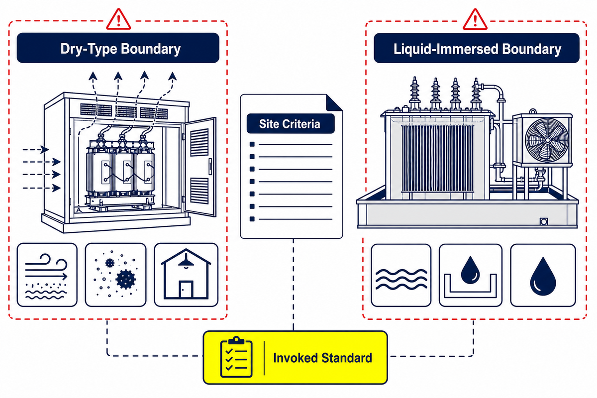
A dry-type transformer and an oil-immersed transformer solve the same energy-transfer problem with different insulation and cooling arrangements. The transformer design choice should begin with the installation environment, fire strategy, ventilation or heat rejection, contamination and moisture exposure, maintenance access, load behavior, noise constraints, local rules, and ownership plan—not a universal claim that one design is better.
Dry-type boundary questions
- Can the space handle the design’s ventilation and heat rejection?
- How will dust, moisture, altitude, and contamination be controlled?
- What fire, enclosure, acoustic, and access requirements apply?
- Which IEC dry-type scope and project clauses are invoked?
Liquid-immersed boundary questions
- What containment, fluid, fire, and environmental rules apply?
- How will radiators, fans, pumps, and alarms be arranged?
- What inspection, sampling, leak response, and access plan exists?
- Which IEEE/IEC test framework and project clauses are invoked?
Scope still matters. IEC 60076-11 applies to dry-type power transformers within its stated boundaries and excludes gas-filled dry types where the gas is not air. IEEE C57.12.90 is a liquid-immersed test code, so its public test list should not be pasted into a dry-type acceptance plan as if the design were the same.
A useful output from this section is not “choose dry” or “choose liquid.” It is a short list of unresolved site conditions, responsible stakeholders, and invoked documents. Without those inputs, a confident recommendation would be marketing language rather than an engineering decision.
Losses, Loading, Cooling, and Temperature Form One Lifecycle Model
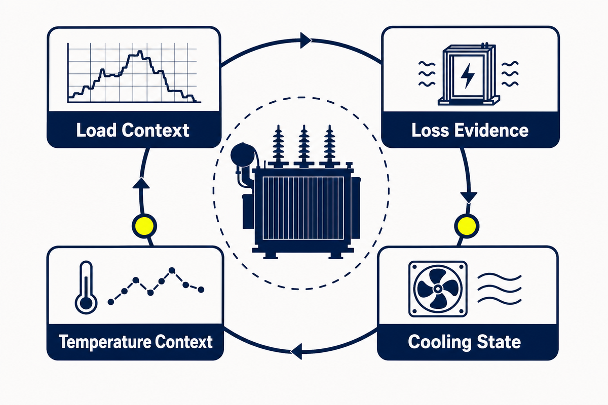
Transformer losses and temperature cannot be reviewed as isolated catalog lines. No-load loss is tied to the energized magnetic system, load loss changes with current and operating condition, and the cooling state affects how heat leaves the active parts. Nameplate ratings therefore need a time-based load and ambient context; reliability cannot be inferred from capacity alone.
For procurement, this means a guaranteed loss value belongs beside its stated test basis and tolerance framework. For the system engineer, the load profile, future growth, harmonics, duty cycle, and redundancy philosophy shape the real operating case. For operations, fan or pump availability, ventilation condition, alarm behavior, and temperature history affect whether the intended cooling state exists in practice.
A single operating temperature is not a universal remaining-life meter. Asset managers need baseline factory and site records, a consistent measurement method, operating context, and trends. Changes that coincide with load, ambient, tap position, cooling availability, or a system event require interpretation before someone labels them “normal” or “degradation.”
Lifecycle rule: compare like with like. Trends are useful only when the measurement method, operating state, and context are known well enough to explain why a value changed.
What Factory Test Evidence Should Prove
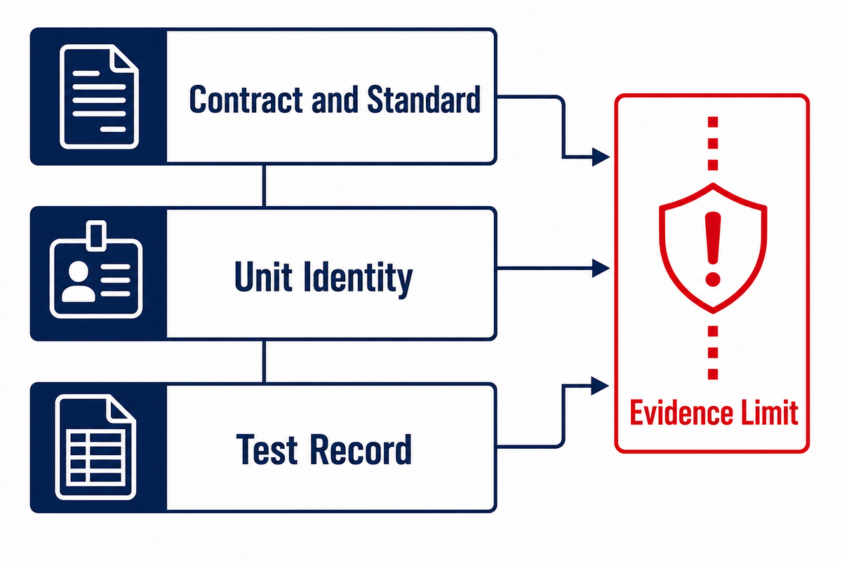
Factory evidence should answer a defined question about a defined unit under an invoked standard and contract. Start with the document hierarchy: approved specification, guaranteed data, applicable standard and edition, agreed test schedule, calibrated records, and the unit-specific report. Test names without that context can create false confidence.
IEEE’s public abstract for C57.12.90-2021 lists resistance, polarity and phase relation, ratio, no-load loss and excitation current, impedance and load loss, dielectric, temperature, short-circuit, and sound-test categories for liquid-immersed transformers. IEC 60076-5 addresses the ability of power transformers to withstand external short circuits. These scope pages identify relevant evidence families; they do not publish every contractual method or acceptance threshold.
| Evidence family | Question it can help answer | What it cannot prove alone |
|---|---|---|
| Winding resistance | Whether measured winding values meet the stated method and comparison basis | Installation connections or future condition |
| Ratio and phase relation | Whether the measured ratio and connection relationship match the unit data | Protection coordination or permission to parallel |
| No-load loss and excitation | How the unit compares with its guaranteed magnetic-system data under the test basis | Site annual energy cost |
| Impedance and load loss | Whether unit values match guaranteed data for studies and loss review | Actual network fault level |
| Dielectric evidence | Whether specified insulation tests were completed under the invoked framework | Site insulation coordination as a whole |
| Temperature-rise evidence | How the design performed under the specified thermal test | Every ambient, enclosure, harmonic, or loading case |
| Short-circuit withstand evidence | Which design/test basis supports the stated withstand duty | That project fault duty and clearing times are acceptable |
| Sound evidence | How the unit performed under the specified sound test | Final site boundary sound level |
Routine, type, design, and special-test labels also depend on the standard and contract in use. Procurement should not assume that a report from another unit is unit-specific evidence, or that a successful design test closes shipping, installation, and commissioning risks. Reports prove only what they record; the acceptance plan must state what else is required.
Protection and System Interfaces Need the Same Data Set
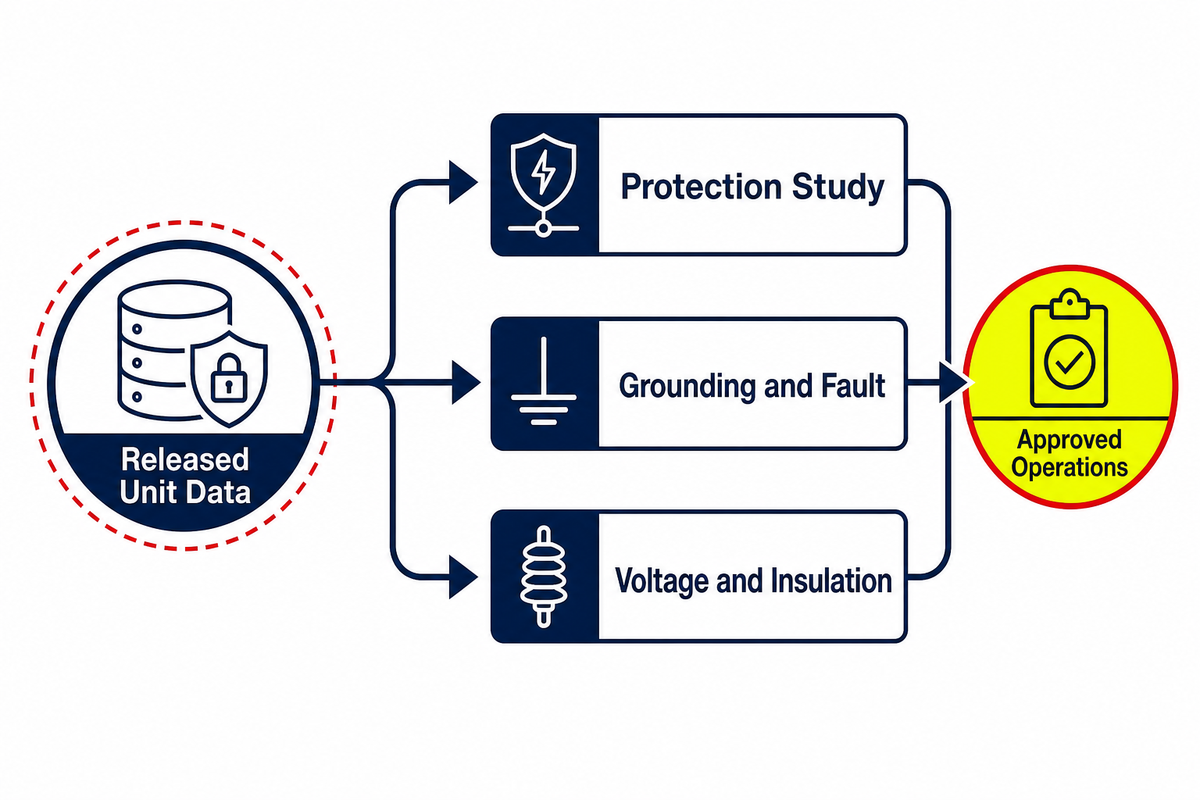
A 35kV transformer becomes part of a system only after its electrical data is reflected in protection, grounding, fault, voltage, and insulation studies. Voltage regulation, power quality, power factor, and high-voltage fault behavior depend on the surrounding network as well as the unit. Ratio, vector group, impedance, tap range, grounding arrangement, CT/VT data, inrush assumptions, system fault levels, and surge interfaces should come from controlled documents—not from a generic product description.
Protection engineers need a version-controlled model that matches the released equipment data. Operations needs to know which settings, alarms, interlocks, and tap rules have been approved. Commissioning needs traceability from those approvals to the installed unit. Procurement closes the loop by preventing uncontrolled substitutions from breaking the study basis.
That chain explains why a “typical” relay setting, fuse size, grounding recipe, or clearance value does not belong in this guide. Actual answers depend on the network and the governing rules. Publishing a universal number would hide the variables that qualified engineers need to see.
Commissioning Readiness Without Unsafe How-To
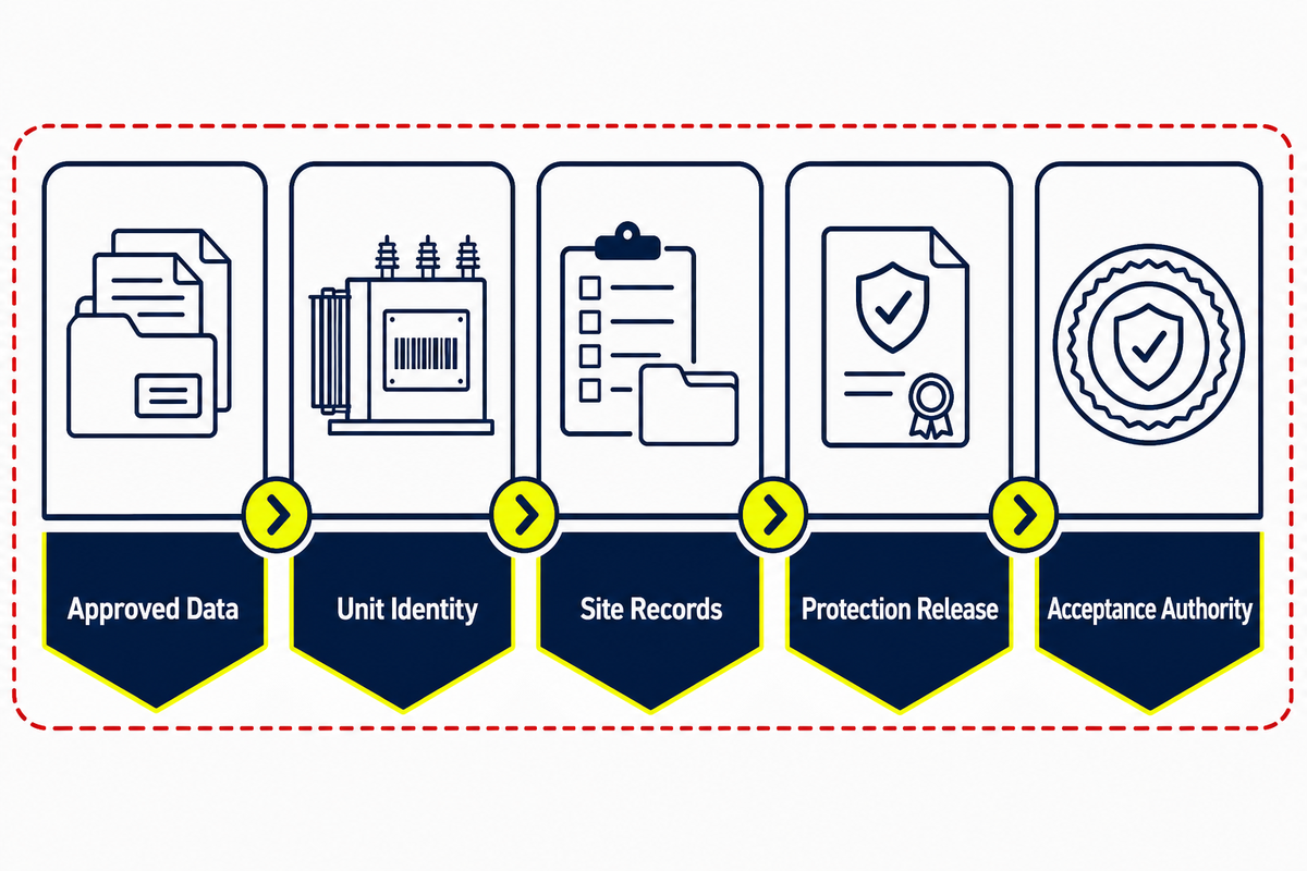
Commissioning readiness is a document and responsibility state before it is a field activity. A safe public checklist should confirm whether released information, unit identity, test traceability, protection approvals, work controls, and acceptance authority are aligned. It does not tell a reader how to perform medium-voltage testing or energization.
- Freeze approved data — reconcile the single-line diagram, data sheet, nameplate fields, manuals, and factory reports.
- Confirm unit identity — match the installed asset and accessories to released records.
- Review shipping and storage evidence — route unresolved observations to the responsible technical authority.
- Bind site records — keep methods, instruments, results, exceptions, and approvals traceable.
- Release protection and controls — confirm that settings, logic, alarms, interlocks, and study inputs share the approved revision.
- Assign acceptance authority — identify who can clear exceptions and authorize the next state.
- Use the site energization plan — qualified personnel follow the applicable safety and operating procedure.
OSHA scope depends on the employer and work. 29 CFR 1910.269 covers electric power generation, transmission, and distribution operations within its scope, while 29 CFR 1910.333 covers general electrical safety-related work practices and uses deenergization as the default for exposed live parts unless a stated exception applies. Project EHS and electrical authorities determine the applicable path.
Maintenance Decisions Over the Asset Life
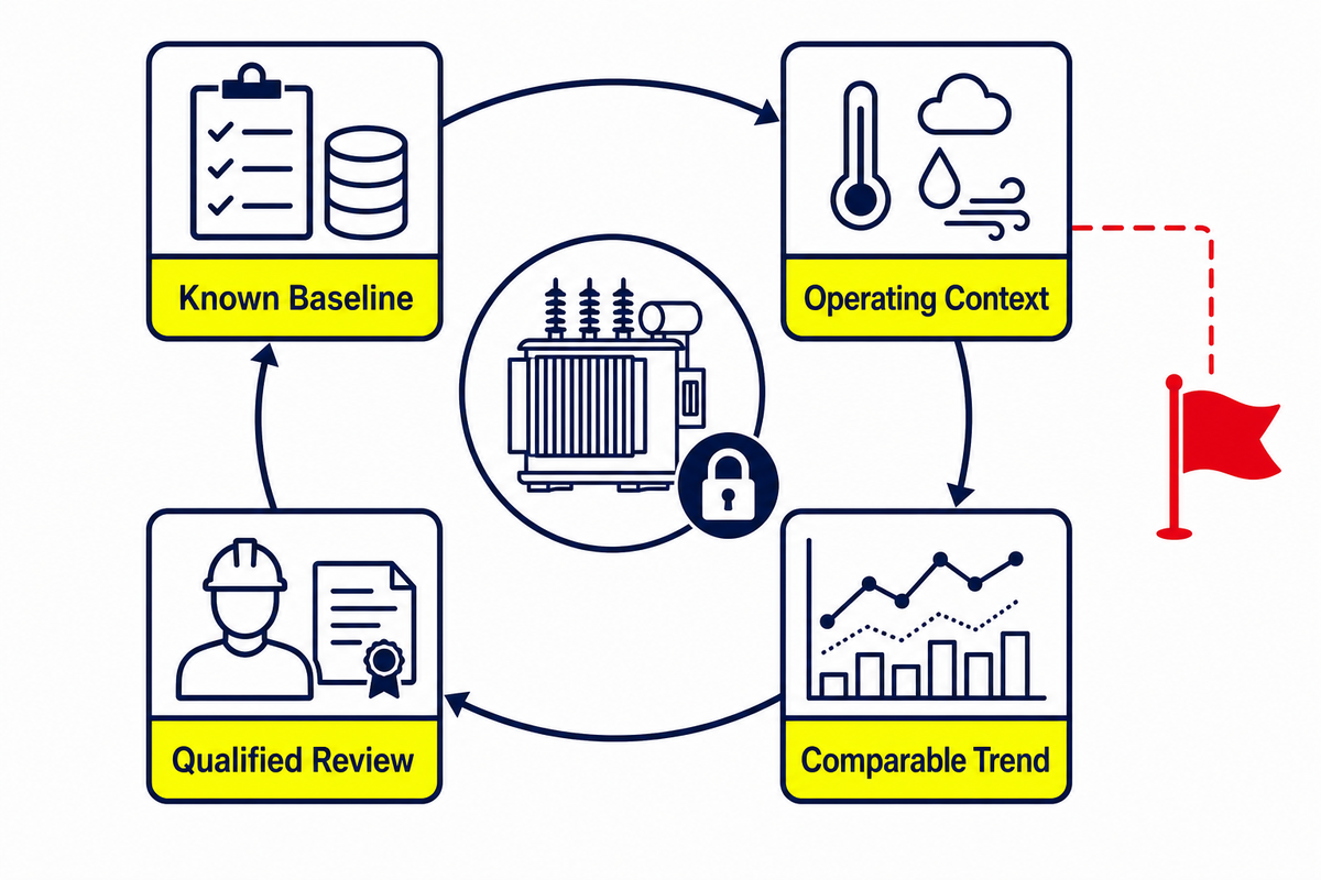
A maintenance program should compare present evidence with a known baseline and operating context. Factory and commissioning records form the baseline, which then grows through inspections, alarms, operating events, loading, temperatures, cooling status, qualified diagnostics, and corrective actions. One observation rarely answers the whole condition question.
Condition indicators also depend on construction. Liquid-immersed equipment may bring fluid, containment, leak, bushing, cooling, and auxiliary records into the review. Dry-type equipment may shift attention toward enclosure condition, ventilation paths, contamination, moisture, connections, temperatures, and insulation-system evidence. Applicable manuals, owner procedures, environment, and service history decide the method and interval.
Trend quality matters more than a decorative dashboard. Record the method, instrument, operating state, ambient context, load, tap position, and cooling state well enough that the next reviewer can compare like with like. When a trend changes, define the decision it triggers—more review, a controlled outage, a qualified diagnostic, or an engineering assessment—rather than treating every deviation as an automatic failure.
35kV Evidence-to-Decision Matrix
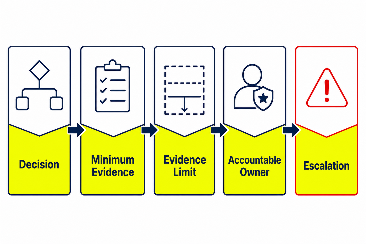
An evidence-to-decision matrix keeps a project from asking one document to do every job. It links each decision to its minimum evidence, states what that evidence cannot prove, and assigns an accountable stakeholder. Teams can use it as a meeting register without turning it into a product selector or an energization procedure.
| Decision | Minimum evidence | Cannot prove alone | Accountable stakeholder | Escalate when |
|---|---|---|---|---|
| Regulatory scope | Rated input/output, frequency, capacity, design category, exclusions, manufacture date | That every 35 kV label has the same treatment | Compliance plus owner’s engineer | Category or threshold data conflict |
| System fit | Approved single-line, ratio, vector group, impedance, taps, insulation basis | Installation quality | Design and protection engineers | Equipment data and study model differ |
| Design type | Environmental, fire, ventilation, maintenance, load, code, and insurer criteria | Universal superiority of dry or liquid designs | Owner, engineer, AHJ, and insurer | A governing criterion has no owner |
| Factory acceptance | Contract, standard/edition, guaranteed data, test schedule, unit report | Shipping or site readiness | QA and owner’s engineer | Report identity, method, or result is unclear |
| Energization readiness | Released drawings, site records, protection/control approvals, work plan, exception closure | Long-term performance | Commissioning authority and operations/EHS | An exception lacks documented disposition |
| Maintenance action | Baseline, trends, qualified diagnostics, operating context, applicable procedure | Remaining life from one reading | Asset manager and qualified specialist | Trend, context, and consequence disagree |
This matrix also exposes commercial handoff timing. Once the project has a controlled voltage basis, load data, site conditions, insulation/protection interfaces, and evidence requirements, a supplier can discuss construction and configuration without guessing. That is the point to move from evidence review to a project-specific 35kV transformer discussion.
35kV Power Transformer FAQ
Is 35kV medium voltage?
35 kV is commonly handled in medium-voltage equipment contexts, but the controlling classification depends on the adopted standard, jurisdiction, equipment scope, and document using the term.
Use the project’s adopted voltage-class convention and governing standard. Different documents may be describing nominal system voltage, rated winding voltage, an insulation class, or highest voltage for equipment. Those values affect different study and acceptance decisions. Do not infer equipment ratings, regulatory coverage, clearances, or work rules from the informal medium-voltage label alone.
Is a 35kV transformer the same as a 34.5kV transformer?
No—not without context. Related system and equipment discussions may use both terms, but their winding ratings, taps, insulation data, and regulatory treatment are not automatically interchangeable.
Check the actual rated winding voltage, taps, system nominal voltage, insulation data, frequency, and regulatory purpose. The 34.5 kV value in 10 CFR 431.192 is one U.S. regulatory boundary with additional input voltage, output voltage, capacity, frequency, and equipment-category conditions. It is not a naming rule for every global product. Reconcile the project single-line diagram, nameplate, guaranteed data, invoked standards, and study model before treating the two labels as equivalent.
What is the difference between a power transformer and a potential transformer?
A power transformer transfers load power between voltage levels; a potential transformer supplies a scaled voltage signal to metering or protection circuits and belongs to a different equipment family.
The secondary circuit’s job is the fastest family check. A load-serving unit and an instrument transformer require different ratings, burdens, accuracy or loading evidence, test frameworks, and acceptance logic. Power-transformer standards can expressly exclude instrument transformers, so confirm the electrical duty before comparing products, drawings, or factory reports that happen to share a 35 kV phrase.
What tests should appear in a factory test report?
Factory reports should contain the tests required by the invoked standard, edition, purchase specification, approved test schedule, and specific unit identity—not a generic universal checklist.
Common evidence families include resistance, ratio/phase relation, loss, impedance, dielectric, and other design-specific records. Do not treat a generic checklist as the contract, and do not treat another unit’s report as unit-specific proof.
How do you choose dry-type or liquid-immersed?
Choose dry-type or liquid-immersed only after comparing site environment, fire and containment strategy, ventilation or heat rejection, load, maintenance access, code, insurer, acoustic, and ownership requirements.
Neither design is a universal winner. Project teams should document the criteria and unresolved tradeoffs before asking a supplier to configure the unit.
How long does a 35kV transformer last?
No credible service-life number can be assigned from the 35 kV label alone; condition, loading, temperature, environment, maintenance, and operating events all influence the decision.
Design, loading, temperature history, environment, cooling, maintenance, events, insulation condition, and operating practice all matter. Use baseline records, consistent trends, and qualified condition assessment for asset decisions.
Key takeaway
A 35kV transformer decision is ready only when the voltage label, nameplate, studies, invoked standards, unit evidence, site records, and accountable approvals describe the same asset.
Turn Evidence Into a Project Discussion
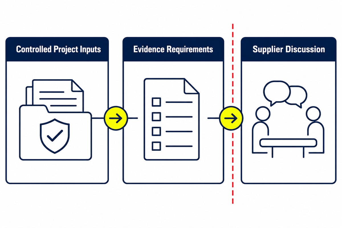
A defensible specification begins with controlled project inputs, not a generic model request. Start with the single-line diagram, voltage and frequency basis, load profile, site conditions, insulation/protection studies, construction constraints, required standards and editions, test expectations, and document list. Teams that need a wider terminology refresher can first read the general power transformer guide.
Toplit’s public product page is the commercial owner for construction and configuration questions. You can also learn about Toplit before deciding whether the supplier context fits your project.
Have a controlled 35kV project data set?
Bring the voltage basis, load profile, site constraints, study inputs, and evidence requirements to a project-specific review.
References & Sources
- 10 CFR 431.192 — Definitions, Electronic Code of Federal Regulations.
- IEC 60076-11:2018 — Dry-type power transformers, International Electrotechnical Commission.
- IEEE C57.12.90-2021 — Liquid-immersed transformer test code, Institute of Electrical and Electronics Engineers.
- IEC 60076-5 — Ability to withstand short circuit, International Electrotechnical Commission.
- 29 CFR 1910.269, Occupational Safety and Health Administration.
- 29 CFR 1910.333, Occupational Safety and Health Administration.
- 10 CFR 431.196 — Energy conservation standards, Electronic Code of Federal Regulations.
Editorial scope: Public standard pages establish scope and test categories; the applicable purchased standard, project specification, local rules, and qualified engineering review control the actual work.
![Pad-Mounted Transformer: How It Works [2026 Guide]](https://toplit-transformer.com/wp-content/uploads/2026/08/pad-mounted-transformer-guide-featured-150x150.png)
![Single Phase Pad Mounted Transformer Guide [2026]](https://toplit-transformer.com/wp-content/uploads/2026/08/single-phase-pad-mounted-transformer-guide-featured-1-150x150.png)