Get in touch with Talite Transformer Co., Ltd Company

Dry-Type Transformer: A Complete Guide to Types, Selection, and Maintenance

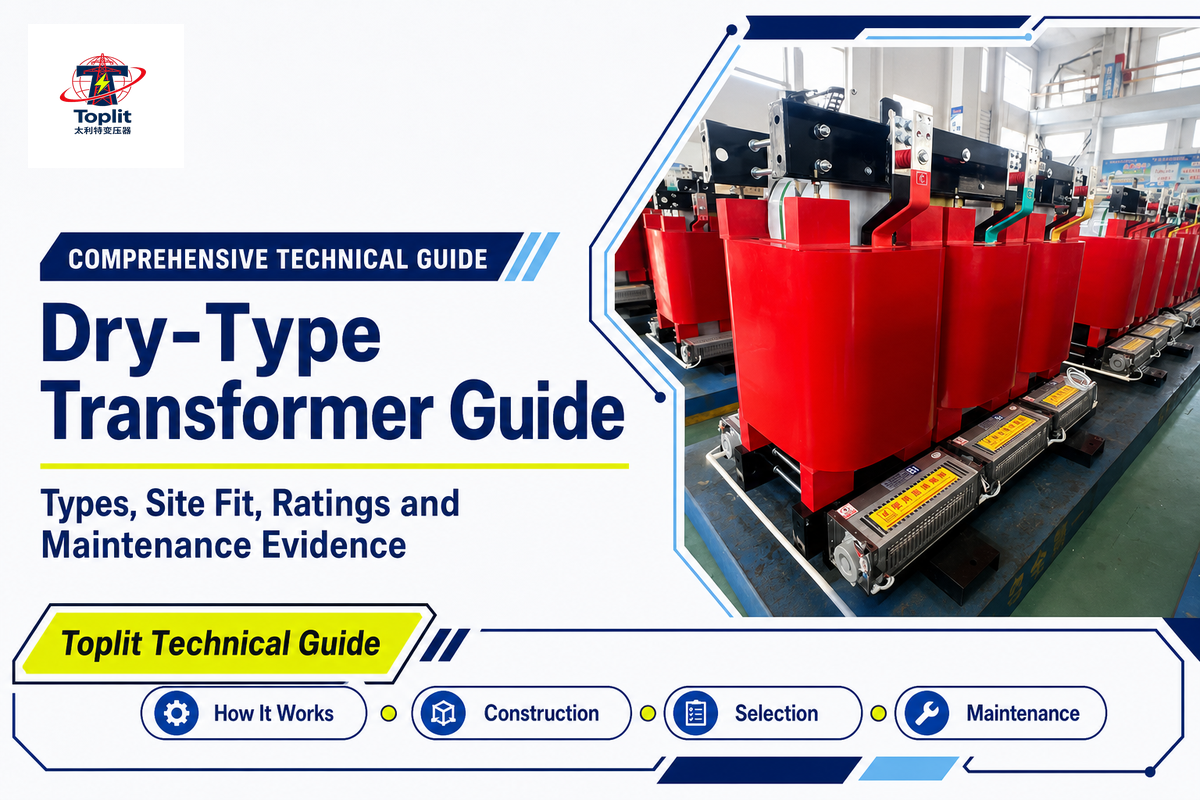
The dry-type transformer is a static AC device that uses air and solid insulation instead of immersing its active parts in insulating liquid; it transfers AC power between windings through electromagnetic induction.
Though useful, this definition falls short of a full specification. “Dry-type” doesn’t include needed information such as required kVA, voltage ratio, enclosure, temperature rise, harmonic capability, environmental class, test evidence, or whether the device is adequate for your location.
This guide clarifies that description from an engineer’s viewpoint. You’ll learn the principles of dry-type transformers and windings and how design variations impact the choice and the site conditions that influence the decision. This guide will also assist you in understanding how to interpret ratings and understand the service and evidence that must be retained during the life cycle of the device. If you’re already comparing project-specific models, ratings, and configurations, use Toplit’s dry-type transformer solution page as the commercial specification owner.
Category boundary
Dry-type tells you: the active part isn’t immersed in insulating liquid.
Dry-type does not tell you: the full electrical duty, winding protection, enclosure, installation environment, losses, approval status, or maintenance plan.
What Is a Dry-Type Transformer?
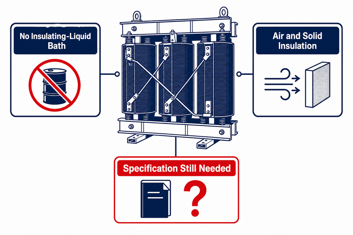
Dry-type transformers are static AC devices whose cores and windings are insulated and cooled without an insulating-liquid bath. Air usually carries heat away from the active parts, while varnish, epoxy, cast resin, solid barriers, and the enclosure provide different levels of electrical and environmental protection. “Dry” doesn’t signify the absence of resin, the absence of varnish, or a cool-running or maintenance-free device.
The category covers more than one standard. IEC 60076-11:2018 covers a defined group of dry-type power transformers up to and including 72.5 kV, requires at least one winding above 1.1 kV, and lists exclusions. IEEE C57.12.01-2020 describes ventilated, non-ventilated, and sealed dry-type distribution and power transformers with the highest-voltage winding of 601 V or more. Thresholds and exclusions differ. Because those thresholds and exclusions differ, a dry-type transformer specification that treats one label as the whole scope creates a mismatch risk. Neither should be stretched to include every product termed dry-type by someone.
This distinction is important because to some extent, a name can feel more complete than it is. Two units can both be dry-type, yet they can differ in winding encapsulation, conductor, insulation system, thermal class, temperature rise, impedance, enclosure, sound-control features, accessories, and test program. The appropriate question isn’t simply “Do we need dry-type?” It’s “Which dry-type construction, under which duty and site conditions, supported by which evidence?”
How a Dry-Type Transformer Works
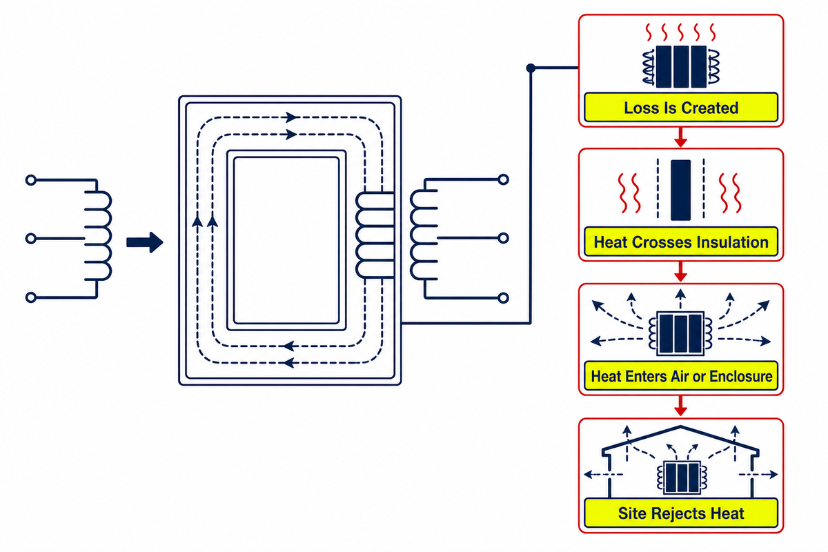
The electrical principle is the same as in a liquid-filled transformer. Applying voltage to the primary winding produces varying magnetic flux in the core. This changing flux is linked to the secondary winding and thus generates voltage in the secondary winding.
A dry-type transformer working principle diagram should show this changing flux, the secondary winding, and the induced voltage; omitting the heat path creates an overheating risk before a factory test report is reviewed. The primary and secondary windings don’t connect to each other electrically. A dry-type transformer diagram should show the primary and secondary windings without implying that they connect electrically. Rather, they transfer energy through the magnetic field.
The dry-type distinction appears in the insulation and heat path. Current in the windings creates resistive loss. Alternating magnetic flux creates core loss. There are stray fields that create loss in structural and conductive components. The losses are converted into heat that must flow from the core and coil assembly, through insulation and the air passages, into the surrounding environment. An air-cooled design may use natural airflow or forced air cooling, but the declared cooling stage must match the rating and the applicable dry-type transformer requirements.
| Heat-path stage | Question to close | Evidence to request |
|---|---|---|
| Loss is created | What are no-load, load, and additional losses at the stated test basis? | Guaranteed loss schedule and applicable test report |
| Heat crosses insulation | What insulation system, winding construction, and temperature-rise limit apply? | Design description, nameplate data, type-test evidence where required |
| Heat enters air or enclosure | Is cooling natural, forced, ventilated, or through a non-ventilated surface? | Cooling designation, fan logic, enclosure drawings, manufacturer instructions |
| Site rejects heat | Can the room or outdoor location remove heat at the actual ambient and altitude? | Ventilation study, layout, ambient profile, altitude and obstruction review |
This heat path map shows a typical specification error. A unit may have a rated kVA and still be incorrectly installed when the room ventilation, the openings in the enclosure, altitude, ambient temperature, harmonics or nearby heat sources aren’t the same as in the design.
The nameplate rating and installation environment must be evaluated together.
The Main Dry-Type Transformer Constructions
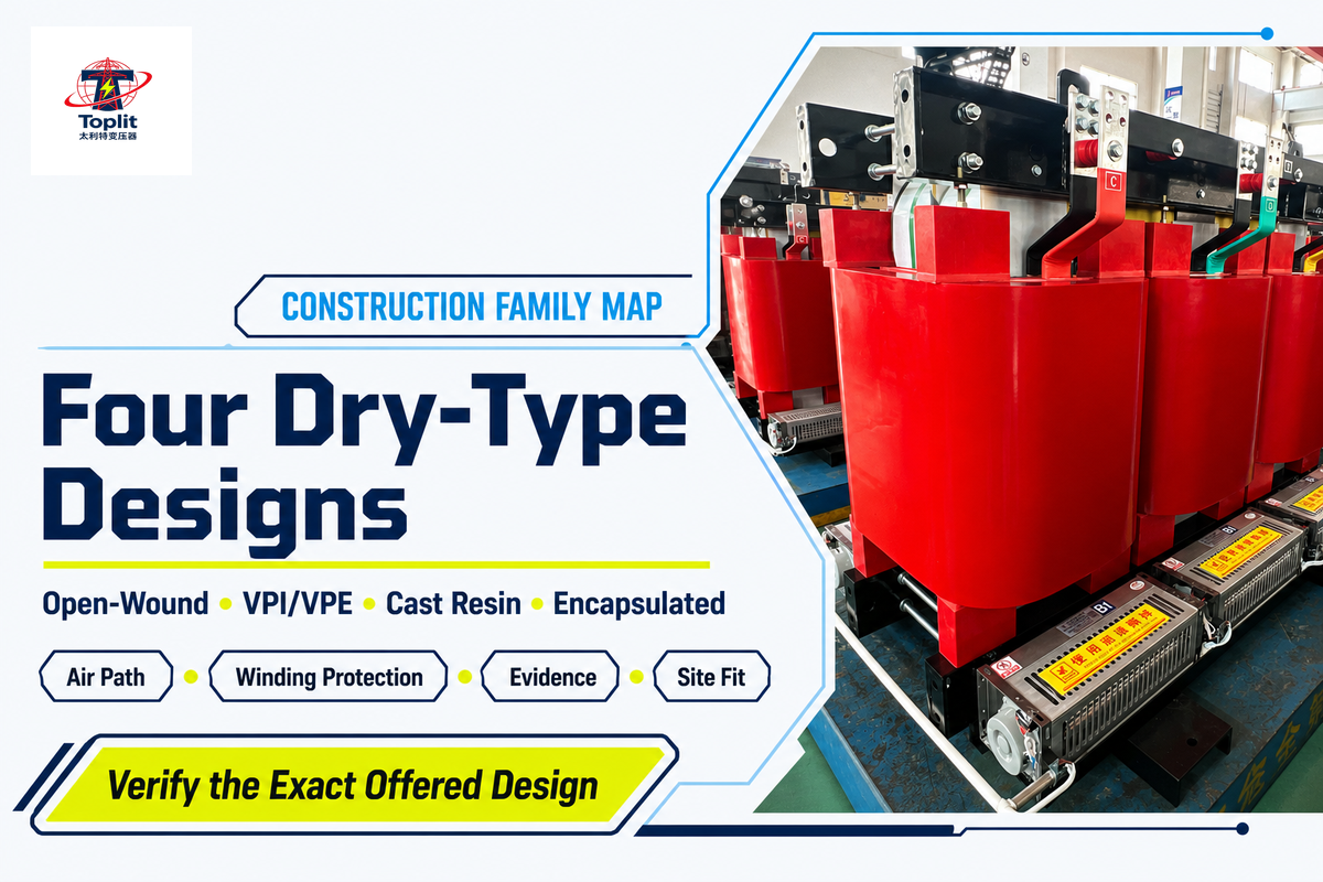
There’s no single universal classification used by all manufacturers. Dry-type distribution transformers can use different winding and enclosure constructions. The following is a practical reading model. The detail and terminology must still be verified in the technical offer. That construction detail and terminology should be checked against IEC 60076-11 and the model-specific test report in the technical offer.
| Construction | What it generally describes | Typical decision advantage | Boundary to verify |
|---|---|---|---|
| Open-wound or ventilated | Windings exposed to cooling air through enclosure openings, usually with solid insulation and a varnish system | Direct air cooling and service access | Dust, moisture, corrosive contamination, airflow blockage, and room cleanliness |
| VPI or VPE | Windings impregnated under vacuum-pressure processes, with VPE generally indicating repeated or enhanced encapsulation passes depending on the supplier | Improved consolidation and environmental protection compared with basic open winding | Exact resin system, process definition, coating coverage, and test evidence |
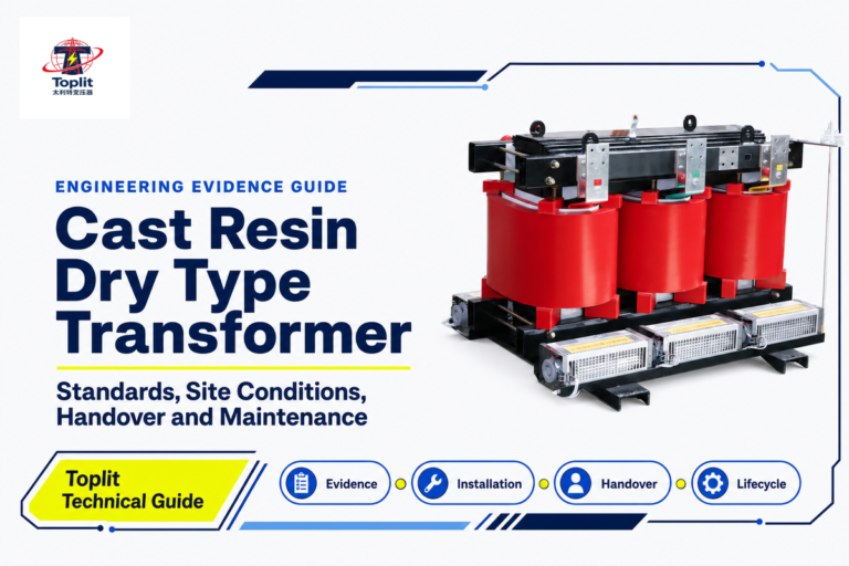
| Cast-resin or cast-coil | Windings, commonly high-voltage coils, cast in solid resin under controlled conditions | Greater winding isolation from moisture and contamination in many designs | Crack resistance, thermal cycling, repair strategy, environmental class, and casting evidence |
| Encapsulated or non-ventilated | Active parts protected by encapsulation or an enclosure without normal ventilation openings | Reduced direct entry of contaminants | How heat leaves the enclosure, allowable ambient, surface temperature, rating range, and terminology |
Labels may overlap. A VPI transformer may be ventilated. An encapsulated low-voltage unit isn’t necessarily the same as a medium-voltage cast-coil transformer. “Sealed,” “totally enclosed,” and “non-ventilated” may also refer to different construction details. The label should only be the beginning of an exhaustive review of the documentation and not the closing decision.
The most useful comparison is evidence-based. Ask where resin or varnish is applied, if air touches windings, how cooling air moves, what parts are cast or coated, how terminals are protected, what environmental or climatic classification is declared, and what tests show the offered construction. This way, brochure terms won’t convey more meaning than the design supports.
Let Site Conditions Drive the Construction Decision
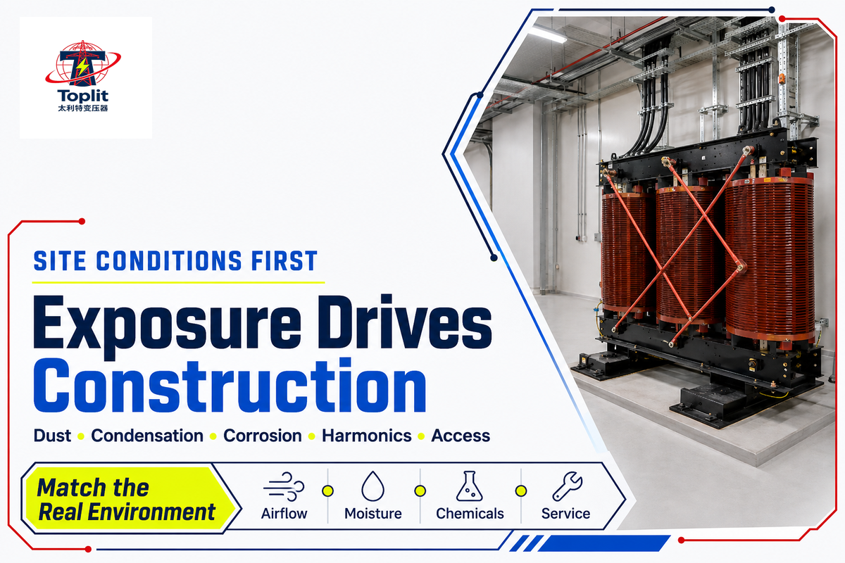
Begin with exposure, not with a preferred product name. A clean electrical room with controlled temperature poses a different problem than coastal plants, process buildings, wastewater facilities, data centers, or outdoor industrial sites. Construction is a function of the combination of contamination, moisture, condensation, ventilation, the fire risk context, access, and the function to be performed.
| Site question | If the answer is “yes” | What to verify next |
|---|---|---|
| Can conductive or abrasive dust reach cooling passages? | Open ventilation paths may need stronger controls or a different construction | Dust type, concentration, filtration, cleaning access, and enclosure compatibility |
| Can humidity become condensation during shutdown or temperature change? | Steady-state humidity data alone are insufficient | Condensation cycle, space heaters, storage plan, insulation system, and restart procedure |
| Are corrosive gases, salt, or chemicals present? | A generic indoor/outdoor label may miss material compatibility | Concentration, exposure duration, coatings, terminals, fasteners, and declared environmental class |
| Is the load rich in converters, UPS systems, drives, or switched power supplies? | RMS current and kVA may not capture added harmonic heating | Harmonic spectrum, neutral current, K-factor or other capability evidence, and loss evaluation |
| Is service access limited? | A durable construction may still be a poor lifecycle fit | Inspection access, fan replacement, cleaning path, lifting route, spare parts, and outage window |
IEC 60076-11 includes climatic, environmental, and fire-behavior considerations within its scope. Those classifications should not be replaced by loose claims such as “fireproof,” “weatherproof,” or “maintenance-free.” Fire safety depends on the complete equipment and installation strategy. The applicable standard, declared class, test evidence, local code, and exact installation still need to align.
Experience also shows why a single condition indicator shouldn’t trigger a remote conclusion. Record dust near a louver, an unusual sound, a warm enclosure, or a change in odor. Their significance depends on location, load, ambient conditions, ventilation, construction, and history. Put safety first, record the data, and refer the finding to the owner’s qualified person.
Dry-Type vs Liquid-Filled Transformers
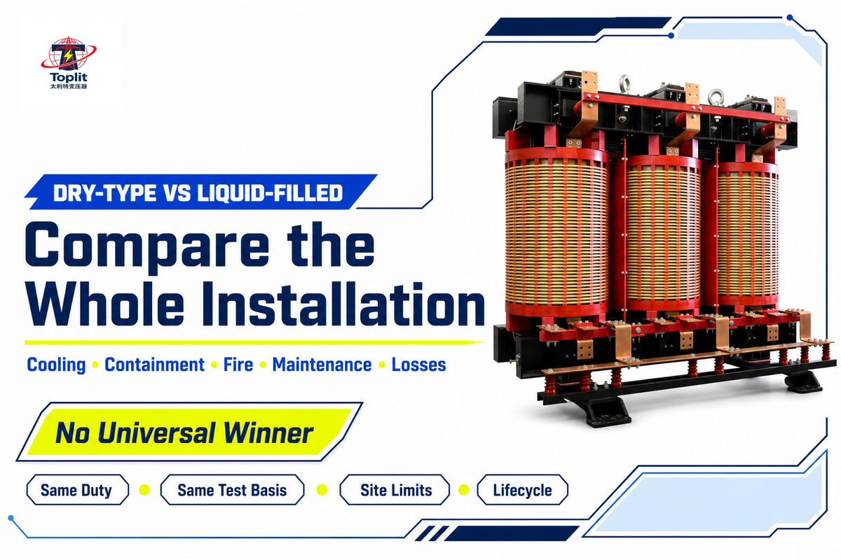
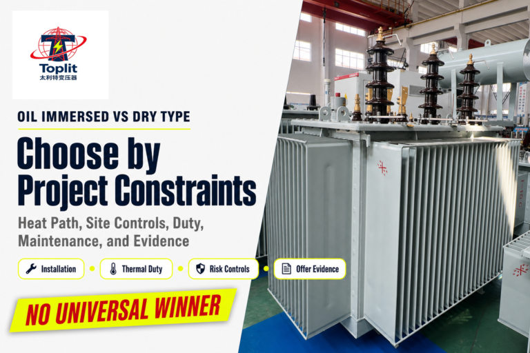
Constructed systems aren’t universally better or worse; neither dry-type nor liquid-filled systems are automatically superior. Each has its own set of tradeoffs, and the physical differences fundamentally change the management of insulation, cooling, containment, fire risk, footprint, environmental exposure, maintenance, and rating. The best point of comparison for any system should be the project’s limitations.
| Decision dimension | Dry-type question | Liquid-filled question |
|---|---|---|
| Installation context | Can air paths, enclosure, room ventilation, and contamination control support the duty? | Can the site manage liquid containment, fire protection, preservation system, and fluid service? |
| Rating and footprint | Does the required rating fit the available construction, sound, cooling, and space limits? | Does the tank, cooling equipment, clearance, and containment footprint fit? |
| Environmental exposure | Are winding protection and enclosure evidence adequate for moisture, dust, salt, or chemicals? | Are tank protection, seals, fluid, preservation, and leak controls adequate? |
| Maintenance strategy | Can the team inspect air paths, connections, insulation condition, fans, and enclosure? | Can the team manage fluid condition, leaks, seals, accessories, and sampling under an approved program? |
| Loss evaluation | Are no-load and load losses suitable for the actual load profile? | Are no-load and load losses suitable for the same load profile and test basis? |
Dry-type units remove transformer-oil leak management from the maintenance scope. However, transformer-oil leak management is just one of the issues that must be addressed alongside fire, environmental, and lifecycle suitability. Compare the full installation and maintenance requirements for both options.
Don’t attempt to compare unlike scopes. Though both may bear the label of dry-type, a small, low-voltage ventilated transformer and a medium-voltage cast-resin unit may both solve very different problems. Also, a distribution transformer efficiency rule may exclude configurations that remain dry-type in general engineering terms. Fix the application, voltage class, rating, installation, and the governing standard, such as the applicable IEEE dry-type transformer practice, before making a comparison.
Which Ratings Actually Matter?
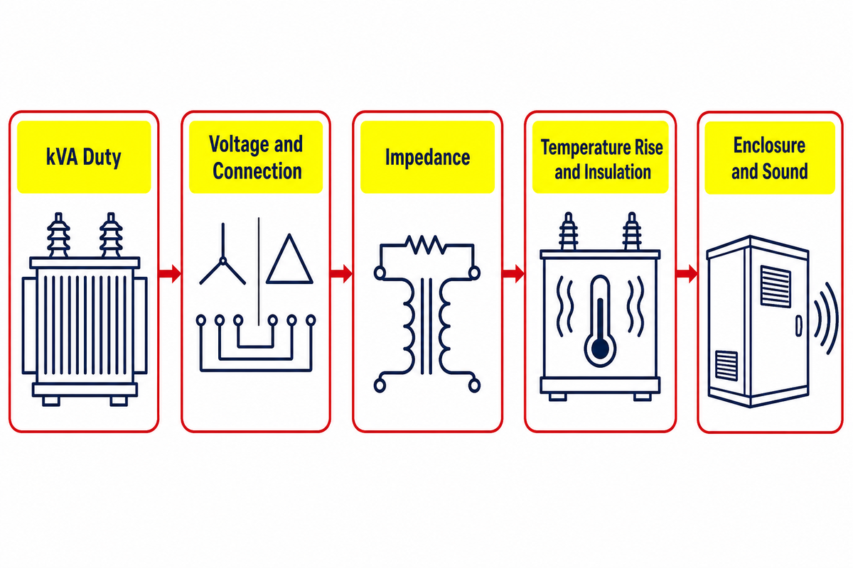
kVA is a necessary rating to understand, but it’s still only one part of the final decision; voltage ratio, phase, frequency, impedance, taps, losses, thermal limits, enclosure, and site conditions also affect suitability. Each rating answers a different question, and leaving one implicit can move risk into installation or operation.
| Rating type or attribute | The question it answers | What it does not answer alone |
|---|---|---|
| kVA | What apparent-power duty is assigned at stated conditions? | Voltage compatibility, harmonic heating, overload permission, or room ventilation |
| Primary/secondary voltage and connection | How does the unit interface electrically? | System grounding, protection coordination, tap use, or transient duty |
| Frequency and phase | What supply system is assumed? | Operation at another frequency or phase arrangement |
| Impedance | How does the transformer affect fault current and voltage regulation? | Protection settings or parallel operation without the rest of the study |
| Insulation level and dielectric tests | What dielectric duty and verification basis apply? | Destination-market acceptance or exact product certification |
| Temperature rise and insulation system | What thermal design limits are declared at stated conditions? | Actual winding temperature under an unknown load, ambient, altitude, or harmonic spectrum |
| Conductor material | What winding material is used? | Efficiency, size, thermal performance, or quality without the completed design |
| Enclosure | What access and environmental protection construction is declared? | Outdoor suitability without installation, drainage, condensation, corrosion, and approval evidence |
| Sound level | What test value or limit is offered? | Room acoustics, structural transmission, or perceived sound at an occupied position |
A comparison line might read 500 kVA, 11 kV/415 V, 50 Hz, 6% impedance, 100 K temperature rise, 40 °C maximum ambient, 1,000 m altitude, 1.8 kW no-load loss, and 6.5 kW load loss. The values listed are examples of aligned units, and should not be misinterpreted as defaults. Each value must be extracted from the project specifications, applicable standards, and the offered design.
The operating profile must be normalized as well. The figures that follow are meant to be illustrative. They demonstrate the reason why two offers can’t be compared until both have been assessed against one fixed operating profile.
| Profile field | Illustrative case A | Illustrative case B |
|---|---|---|
| Annual energization | 8,760 hr | 6,000 hr |
| Average load | 25% | 45% |
| Peak load | 80% | 90% |
| Maximum ambient | 30 °C | 40 °C |
| Site altitude | 500 m | 1,000 m |
| Secondary voltage | 415 V | 480 V |
| System frequency | 50 Hz | 60 Hz |
| Example access allowance | 300 mm | 450 mm |
Nonlinear loads deserve their own line. IEEE C57.110-2018 provides methods and application information for transformers supplying nonsinusoidal load currents. That’s a useful warning against selecting only by fundamental-frequency kVA. A K-rated transformer is intended to tolerate defined harmonic heating; it doesn’t automatically cancel harmonics. A harmonic-mitigation or motor drive transformer addresses a different system objective, while drive isolation adds another application boundary.
Overcurrent protection is still a system study. The transformer rating and impedance are relevant to calculations of fault current, but protection still needs to be coordinated with conductors, upstream and downstream devices, inrush current, grounding, and the code.
Losses, Heat, Efficiency, and Loading
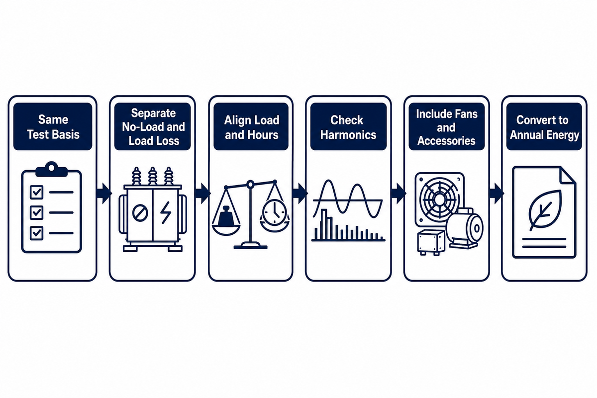
Energizing a magnetic core causes no load losses. However, the no-load loss remains as long as the transformer is energized. Load losses are higher with current and comprise winding resistance and additional stray effects. With a simplified model, the resistance component changes approximately with current squared. In these cases, a purchase comparison must use loss data provided by the manufacturer and the applicable test basis.
This explains why a single efficiency percentage can mislead. Efficiency is evaluated at defined loading, temperature, and power-factor conditions. Your site may spend most of the year far from that point. The BPA dry-type transformer report cites an older Cadmus Group study of low-voltage dry-type units in commercial buildings and other facilities in which the measured population averaged 16% RMS load. That bounded example isn’t a modern fleet average, but it demonstrates the decision problem: at light load, continuous no-load loss can matter more than a test-point headline suggests.
Comparable-loss check
- Confirm both offers use the same applicable test basis.
- Separate guaranteed no-load loss from load loss.
- Provide the expected load, energization hours, conditions, and power factor.
- Add harmonic or nonsinusoidal-current evaluation where relevant.
- Check fan or accessory energy and any cooling-stage assumptions.
- Convert losses to annual energy after the inputs have been aligned.
For covered US distribution-transformer models, the Department of Energy ties the corresponding test procedure and revised criteria. The 2024 final rule became effective July 8, 2024, and sets April 23, 2029 as the compliance date for covered models manufactured on or after that date. This is a US covered-product requirement, not a universal deadline for every dry-type transformer worldwide.
Indoor and Outdoor Installation Planning
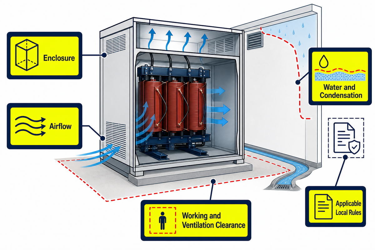
The dry-type label alone doesn’t establish that enclosures are suitable for outdoor use; indoor use and outdoor use require separate verification. A complete installation review connects the enclosure, airflow, water path, condensation cycle, contaminants, ambient, altitude, fire strategy, acoustics, access, and local rules. Where that designation applies, a NEMA Type 3R enclosure answers a defined enclosure-protection question; it doesn’t by itself approve every outdoor installation.
Start with the exact manufacturer instructions. One manual may include construction clearance, inlet area, ambient limit, or storage precaution. Don’t use those values for another model or project. Convert them into verification questions: What are the minimum working and ventilation clearances required? What would happen if a wall, cable tray, filter, snow, or other sources of heat were to impede or obstruct the flow of air? What steps are taken to control condensation after shutdown?
Planning for receiving and storage also begins with installation planning. Record shipping damage prior to acceptance. Inspect for displacement, loose parts, foreign material, and moisture. Follow the manufacturer’s instructions and preserve the storage conditions. These records can distinguish transport or storage exposure from later service changes.
There may be additional boundaries imposed by jurisdiction. For the general industry scope in the US, 29 CFR 1910.305 states that indoor dry-type transformers rated greater than 35 kV must be in a vault. This is a voltage- and jurisdiction-specific rule, not a global layout rule. The project team must identify the electrical, building, fire, environmental, and owner requirements that apply to the actual site.
Maintenance and the Evidence You Should Keep
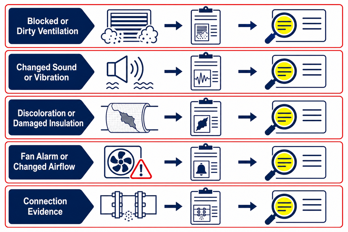
Dry-type transformers don’t require liquid sampling. This equipment doesn’t eliminate the maintenance required for the unit. Base the maintenance program on the manufacturer’s instructions, applicable standards, site risk, unit duty, and observed condition. IEEE C57.94-2025 is an active recommended practice covering the installation, application, operation, and maintenance of dry-type distribution and power transformers.
| Observe safely | Record with context | Escalate through qualified review |
|---|---|---|
| Blocked or dirty ventilation openings | Date, location, contamination type, room condition, and comparison with prior inspection | Cleaning method, outage need, enclosure opening, or contamination-control change |
| Changed sound or vibration | Load, time, switching event, temperature, mounting area, and whether the change is repeatable | Electrical, mechanical, mounting, core, or enclosure troubleshooting |
| Discoloration, odor, tracking, or damaged insulation | Exact location and condition without touching energized parts | De-energized inspection, tests, repair scope, and return-to-service decision |
| Fan alarm or changed airflow | Alarm time, indicated temperature, load, ambient, controller state, and redundant cooling status | Fan, sensor, control, wiring, or thermal-capability assessment |
| Loose, corroded, or overheated connection evidence | Inspection history, accessible visual evidence, load history, and protection events | Safe isolation, torque/test procedure, repair, and root-cause review |
Keep a baseline package. Keep approved drawings, nameplate records, final settings, factory and site test reports, shipping and receiving reports, installation photos, commissioning records, thermal or condition baselines where used, fan and controller details, alarms, maintenance history, and deviations. The condition trend is usually more useful than an isolated observation.
Standards documents also require an evidence ladder, not just a reference. The lowest evidence document might say “designed to.” Above it is a declared standard and edition. Higher levels include model-specific routine-test reports, applicable type-test reports, third-party inspection, and an exact certification or listing record where required. OSHA’s NRTL standards page demonstrates the concept in that recognition of a test standard isn’t verification that a specific product is listed.
A 7-Step Dry-Type Transformer Decision Framework
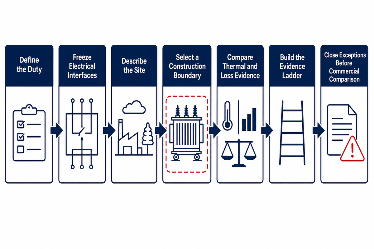
- Define the duty. Show the load profile, starting and cycling duty, redundancy, future growth, power factor, harmonics, energization hours, and required duty.
- Freeze the electrical interfaces. Confirm voltage ratio, phase, frequency, connections, grounding idea, tap range, impedance, insulation level, protection inputs, and constraints for parallel operation.
- Describe the site. Document the indoor or outdoor location, ambient range, altitude, dust, moisture, condensation, chemicals, salt, seismic duty, fire strategy, room airflow, acoustics, and service access.
- Select a construction boundary. Compare ventilated/open-wound, VPI/VPE, cast-resin, and encapsulated/non-ventilated options against the actual exposures. Record why a family is included or excluded.
- Compare the thermal and loss evidence. Consider no-load loss, load loss, temperature rise, insulation, cooling systems, fan energy, harmonics, and the anticipated operating condition.
- Build the evidence ladder. Include applicable standards along with editions, including the current installation and maintenance practice where relevant. Then require model-specific drawings, a nameplate schedule, routine tests, type tests, certificates or listings, factory acceptance, and destination-market evidence.
- Make exceptions closable before commercial comparison. Keep a record of each exception made for each deviation, assumption, open interface, missing document, or owner decision. Only then can you compare lead time, commercial terms, warranty, spares, and lifecycle support.
This output isn’t a generic “best transformer.” Rather, it’s a justifiable construction and evidence package that fits a specific duty and site, while also reducing content cannibalization: the method is taught in this guide, while the solution page remains for comparing transformer options and requesting a custom project offer.
Ready to turn the framework into a project review?
Prepare the load profile, voltage data, site conditions, construction preference, loss requirements, standards, and evidence list. Submit the package for an engineering and commercial review.
Toplit’s manufacturing background, product scope, and stated factory-test approach are summarized on the company page. Consider these statements by Toplit as supplier context, and match every project requirement to the final technical file of the offered transformer.
Frequently Asked Questions
Are dry-type transformers maintenance-free?
No. Dry-type transformers remove liquid sampling and leak-management tasks, but they still need condition-based inspection of cooling paths, connections, insulation, accessories, contamination, sound, and operating history.
No. They avoid liquid sampling and leak management, but air paths, connections, insulation condition, fans, sensors, enclosure, contamination, sound, and operating history still need attention. The correct scope and interval come from the exact manufacturer instructions, applicable standards, site risk, and condition trend. Inspection or service around energized equipment belongs to qualified personnel under the owner’s safety procedure.
Can a dry-type transformer be installed outdoors?
Yes, in some cases, but only when the exact winding protection, enclosure, environmental limits, drainage, condensation control, accessories, and installation method are approved for that outdoor site.
Sometimes, but “dry-type” alone doesn’t establish outdoor suitability. Verify the exact winding protection, enclosure construction, water and drainage paths, condensation control, corrosion exposure, ambient range, altitude, ventilation, terminals, accessories, and the manufacturer’s approved installation. Then check local electrical, building, fire, and environmental rules. A general-purpose indoor ventilated unit shouldn’t be treated as outdoor-ready.
What are the main disadvantages of dry-type transformers?
The relevant tradeoffs depend on the construction, duty, and installation environment; examples include contamination or condensation sensitivity, clean-airflow dependence, footprint or rating constraints, sound concerns, and repair options for encapsulated windings.
Possible tradeoffs include rating or footprint limits, dependence on clean cooling air for ventilated designs, sensitivity to contamination or condensation, sound management, and different repair options for heavily encapsulated windings. The importance of each tradeoff changes with voltage, kVA, construction, site, and duty. Compare project evidence instead of applying one universal disadvantage list to every dry-type design.
How long does a dry-type transformer last?
There is no defensible universal service-life number.
No universal figure is defensible. Use the design assumptions, operating record, and condition trend; a headline lifespan without those boundaries isn’t a project guarantee.
What is the difference between VPI and cast-resin transformers?
VPI draws varnish or resin into a winding under vacuum and pressure, while cast-resin construction embeds all or a substantial part of the winding in a solid resin casting.
VPI generally impregnates a wound coil with varnish or resin under vacuum and pressure, while cast-resin construction embeds all or substantial parts of a winding in a solid resin casting. The practical difference isn’t the label alone. Compare coating or casting coverage, environmental class, thermal cycling, crack resistance, repair strategy, cooling path, test evidence, and the actual site exposure.
References & Sources
- IEC 60076-11:2018, Dry-type power transformers
- IEEE C57.12.01-2020, General Requirements for dry-type Distribution and Power transformers
- IEEE C57.94-2025, Installation, Application, Operation, and Maintenance of dry-type transformers
- IEEE C57.110-2018, Transformer Capability with Nonsinusoidal Load Currents
- U.S. Department of Energy, Distribution Transformers
- Federal Register, 2024 Distribution Transformer Energy Conservation Standards
- Bonneville Power Administration, Dry-Type Transformer Energy Savings Potential
- OSHA, NRTL Appropriate Test Standards
- OSHA, 29 CFR 1910.305
Why we write this
About Toplit Engineering Insights
Toplit publishes transformer field guides from project routing, factory loss-data discipline, and specification review experience. We help engineering and procurement teams compare transformer types, voltage classes, installation constraints, and quotation evidence before they commit to a build.
- Oil-immersed, dry-type and pad-mounted transformer routes
- Loss data, rating schedules and factory evidence
- IEC / IEEE specification and site-input review
- Factory-direct transformer engineering support
Contact Profile
Talk with the Toplit Transformer Team
Company
Toplit Transformer Engineering Team
Toplit Transformer Engineering Team
Factory base
Hai'an, Nantong, Jiangsu, China
Hai'an, Nantong, Jiangsu, China
![Pad-Mounted Transformer: How It Works [2026 Guide]](https://toplit-transformer.com/wp-content/uploads/2026/08/pad-mounted-transformer-guide-featured-150x150.png)
![Single Phase Pad Mounted Transformer Guide [2026]](https://toplit-transformer.com/wp-content/uploads/2026/08/single-phase-pad-mounted-transformer-guide-featured-1-150x150.png)