Get in touch with Talite Transformer Co., Ltd Company


Distribution transformers are the last voltage transformation stage before electricity reaches a building, and in the United States the equipment class is fixed by regulation rather than by engineering habit. Units qualify as covered equipment only if they meet a four-part test in 10 CFR 431.192 and avoid thirteen named exclusions.
Which efficiency levels apply, and which paperwork a supplier owes you, follows from that test rather than from the catalog heading. What follows works through five things that actually change a quote: whether the federal rule reaches your unit at all, which IEEE or ANSI C57 designation governs it, what the nameplate fields fix, what the loss figures cost across a twenty-year life, and which compliance date you have to plan around. Every federal regulatory figure below was read from the eCFR or Federal Register primary text rather than from a vendor restatement; IEEE clause content is cited from public catalog records and utility purchase specifications, since the standards themselves sit behind a purchase wall. One widely repeated number turned out to be wrong.
What Is a Distribution Transformer?
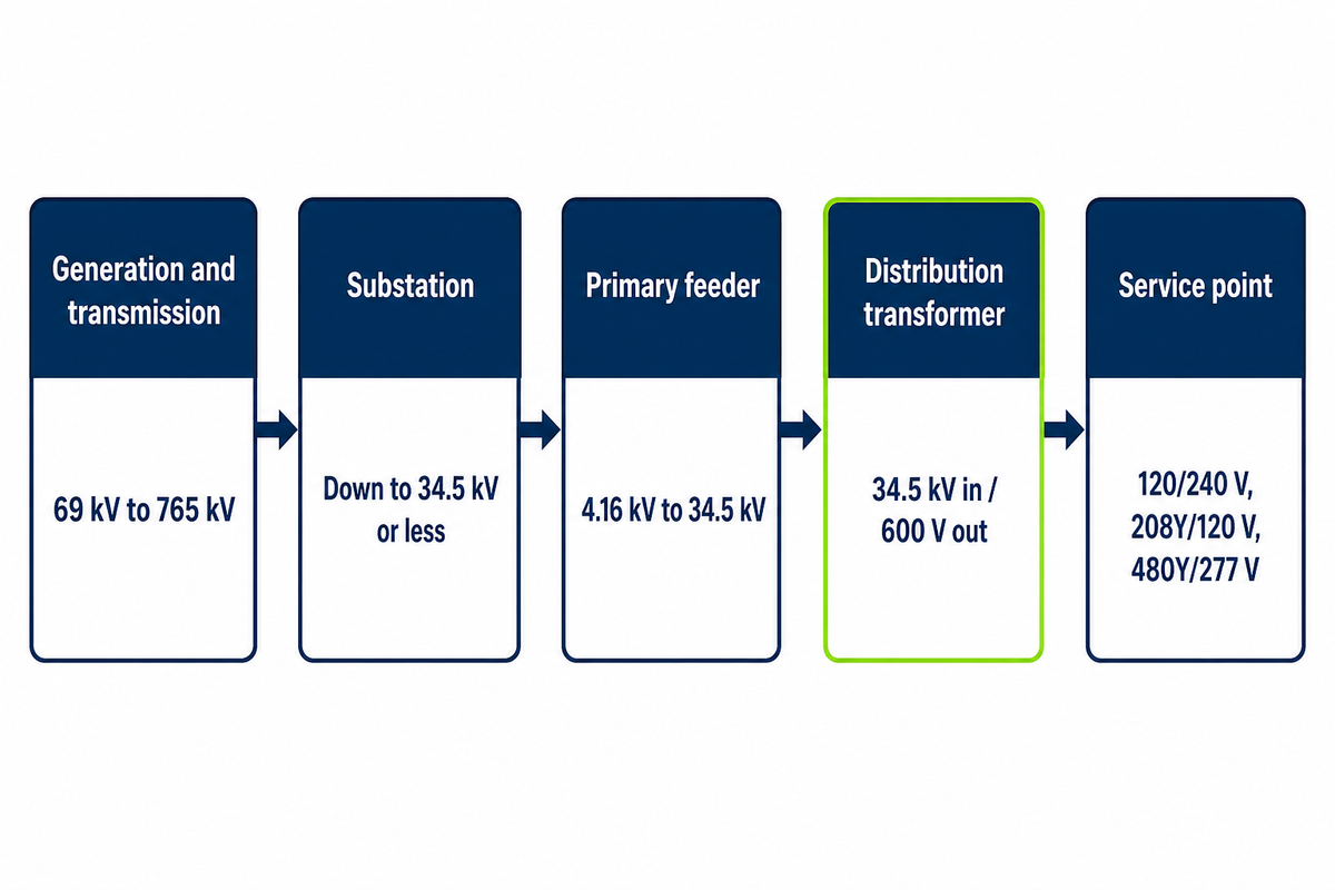
Distribution transformers step medium-voltage feeder power down to utilization voltage at or near the point of use. The catalog heading does not settle the class: United States regulation bounds it at 34.5 kV in, 600 V out, 60 Hz, and a capacity of 10 to 5000 kVA for liquid-immersed units or 15 to 5000 kVA for dry-type units.
Position matters more than appearance. Power generation and long-distance electric power transmission move electrical power at high voltage to hold conductor losses down; a substation drops that to a medium-voltage feeder; the distribution transformer performs the final step-down on the way to the meter. Two units of identical rating can look alike and sit at different points in the electric power distribution system, yet only one counts as covered equipment under 10 CFR 431.192.
| Stage | Typical voltage | What sits there |
|---|---|---|
| Generation and transmission | 69 kV to 765 kV | Power stations, transmission power lines, step-up transformers |
| Substation | Down to 34.5 kV or less | Substation transformers, above the covered-equipment ceiling |
| Primary feeder | 4.16 kV to 34.5 kV | The distribution network, overhead and underground |
| Distribution transformer | 34.5 kV in / 600 V out | Pad-mounted, pole-mounted and dry-type units |
| Service point | 120/240 V, 208Y/120 V, 480Y/277 V | Meter, panel, load |
The upper boundary is where most published descriptions go wrong, and the error is worth naming before it costs anyone a specification round. Many published pages state that the class stops at 33 kV. That figure is the scope statement of an Indian standard, IS 1180 (Part 1):2014; it isn’t the number in American regulation, which sets the input line voltage limit at 34.5 kV. The output side is bounded at 600 V, and a unit above that fails the second condition and leaves the covered class altogether. That is a different boundary from the 600 V that separates low-voltage from medium-voltage dry-type units, which is drawn on input voltage instead.
Scope check: the definition quoted here is the eCFR current text of 10 CFR 431.192 read on 4 September 2026. That section’s own source note lists seven amending citations since 2005, the most recent on 21 January 2025; the compliance-date chain tabulated later in this guide carries only the amendments that bear on the dates, so re-read the primary before relying on it in a contract.
The Scope Test That Decides Whether the Federal Rule Applies to Your Unit
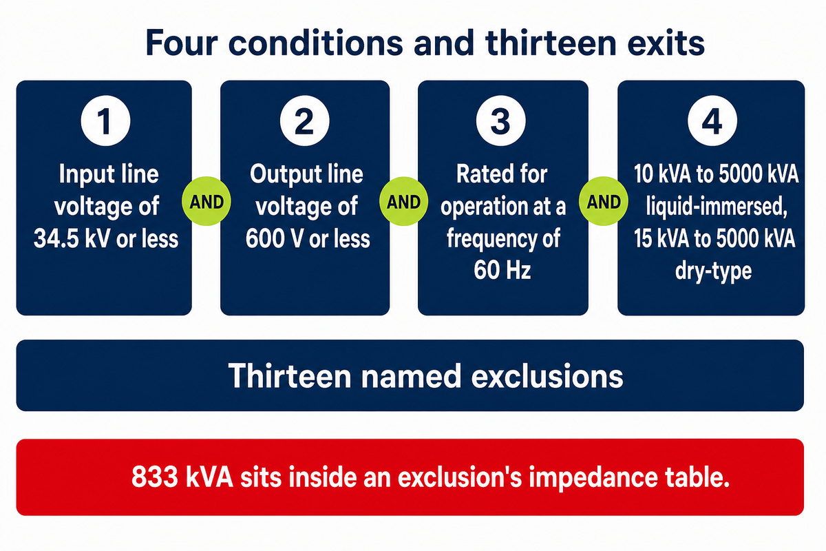
Federal coverage isn’t a product category, it’s a test with four conditions and thirteen exits. The definition quoted below is only half of the test: a transformer counts as covered equipment only if every condition holds at once and no exclusion applies. Those definitions are written for the purposes of that subpart, so catalog and utility usage of the term stays broader than the regulation. Failing any single part puts the unit outside the efficiency rule completely, along with its certification and labeling duties.
Distribution transformer means a transformer that: (1) Has an input line voltage of 34.5 kV or less; (2) Has an output line voltage of 600 V or less; (3) Is rated for operation at a frequency of 60 Hz; and (4) Has a capacity of 10 kVA to 5000 kVA for liquid-immersed units and 15 kVA to 5000 kVA for dry-type units.
Read clause four again, because two things in it are commonly misreported. Capacity divides by insulation type, not by phase count, and the ceiling is 5000 kVA on both sides of that division. Single-phase and three-phase units aren’t given separate bands here at all.
The 833 kVA Ghost Ceiling
Search the topic and you’ll repeatedly find the scope given as 10 to 833 kVA for single-phase power and 15 to 2,500 kVA for three-phase. Both were checked against the section itself. “2500” doesn’t appear in 431.192 anywhere. “833” appears exactly twice, and in neither case as a scope limit: it’s the upper edge of a single-phase band inside the impedance tables attached to the definition of a special-impedance transformer, one of the thirteen exclusions. The three-phase column on the same row runs to 5000 kVA.
That number, lifted out of an exclusion’s impedance table, has been circulating for years as the ceiling for covered units. Anyone can settle it in one fetch of the section, which is the reason it’s worth stating plainly rather than quietly using the right figure.
Exclusions are the half of the test buyers skip, and several of them are things a purchaser can trigger through their own specification. Ask for a tap range of 20 percent or more and the unit leaves covered equipment. In full, they’re: autotransformer, drive (isolation) transformer, grounding transformer, machine-tool (control) transformer, nonventilated transformer, rectifier transformer, regulating transformer, sealed transformer, special-impedance transformer, testing transformer, transformer with tap range of 20 percent or more, uninterruptible power supply transformer, and welding transformer.
Run the four conditions against a spec sheet before requesting quotes and you get a yes or no that changes what the supplier owes you. If the answer is no, the DOE efficiency levels don’t apply and no certification report exists to ask for. Field by field, Talite’s own DOE covered-transformer checker runs the same test.
Four conditions and thirteen exclusions decide federal coverage for one unit, and the capacity band that governs runs to 5000 kVA for liquid-immersed and dry-type units alike. Quoted almost everywhere as the single-phase ceiling, 833 kVA actually sits inside an exclusion’s impedance table rather than in the scope definition.
Which IEEE or ANSI C57 Standard Governs Your Transformer
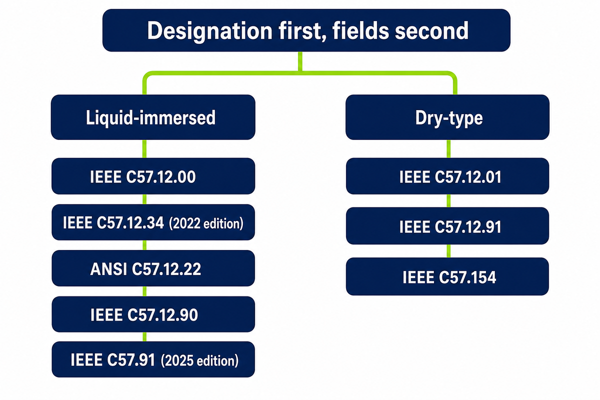
C57 designations divide by insulation medium and mounting arrangement rather than by kVA alone. Each one fixes a different set of parameters and leaves the rest to the purchaser. Choose the governing designation before writing any spec field. Choosing it afterwards means writing fields the designation doesn’t recognize.
Quotes arrive citing C57 numbers as though the number alone settled something. It settles a great deal, but only within its own scope, and the scopes overlap in ways that aren’t obvious from the titles. A dry-type unit and a liquid-immersed unit of the same power rating answer to different general-requirements documents, different test codes, and different nameplate obligations.
Standard-Before-Spec Order of Operations
The sequence runs designation first, fields second. Each designation decides which fields exist for your unit; specifying values before fixing the designation produces a request that a manufacturer has to reinterpret, and two manufacturers will reinterpret it differently. Mapped below are the designations an ordinary distribution transformer purchase actually meets.
| Designation or class | What it governs | When it applies | What it does not cover |
|---|---|---|---|
| IEEE C57.12.00 | General requirements for liquid-immersed distribution and power transformers, including impedance tolerance | Any oil-filled unit, pad-mounted or pole-mounted | Dry-type construction; enclosure and pad interface details |
| IEEE C57.12.01 | General requirements for ventilated, non-ventilated and sealed dry-type units at 601 V and above in the highest voltage winding | Cast resin and open-wound dry-type units | Liquid-immersed units; test procedures |
| IEEE C57.12.34 (2022 edition) | Three-phase liquid-immersed pad-mounted units, 10 MVA and smaller, high voltage up to 34.5 kV nominal, low voltage up to 15 kV nominal | Most commercial and light-industrial pad-mounted transformers | Units above 10 MVA, and anything outside the three-phase pad-mounted configuration |
| ANSI/IEEE C57.12.26 | Three-phase pad-mounted units for use with separable insulated high-voltage connectors, 2500 kVA and smaller | Loop-feed and dead-front underground arrangements | Live-front bushing construction; dry-type units |
| ANSI/IEEE C57.12.22 | Three-phase pad-mounted units with high-voltage bushings, 2500 kVA and smaller | Radial-feed live-front arrangements | Dead-front separable-connector construction; dry-type units |
| IEEE C57.12.90 | Test code for liquid-immersed distribution, power and regulating units, including no-load and load loss measurement | Factory acceptance and routine testing of oil-filled units | Instrument, regulating, arc furnace, rectifier, specialty, grounding and mine transformers, which are excluded from it |
| IEEE C57.12.91 | Test code for dry-type distribution and power units | Factory acceptance of cast resin and open-wound units | Requirements and test criteria themselves, which sit in C57.12.01 or in the user’s specification |
| IEEE C57.91 (2025 edition) | Loading guide for mineral-oil-immersed units, including short-time overload behavior | Anywhere overload capability or aging is being planned | Non-conventional insulation systems, treated in a separate guide |
| IEEE C57.154 | Liquid-immersed units designed to run above the thermal limits of C57.12.00 on high-temperature or hybrid insulation systems | Higher operating temperature or reduced-footprint designs | Dry-type units; conventional 65 °C rise designs |
| Mounting arrangement | Enclosure, pad interface, tamper resistance, accessory placement | Chosen from site constraints, not from the electrical spec | Electrical performance, which mounting does not change |
| Core material | No-load loss level and the mass and cost consequences of reaching it | Where loss capitalization or an efficiency margin is being bought | Any designation boundary; material is a design choice inside them |
Two rows deserve reading together, and the direction of the mismatch is the opposite of what gets published. The current edition of IEEE C57.12.34, dated 2022, runs to 10 MVA, while federal coverage stops at 5000 kVA. A 7500 kVA pad-mounted unit is therefore an IEEE distribution transformer and is not a covered distribution transformer under the efficiency rule. The 2,500 kVA figure that circulates as though it were the regulatory limit is the scope ceiling of the superseded 2004 edition; the 2009 edition raised it to 5 MVA and the 2015 and 2022 editions to 10 MVA. Substation-class machines above 34.5 kV sit outside all of these, which is why the term substation appears in this article as a boundary rather than as a product.
Mounting and core material change the quote without changing the designation: Talite’s own pad-mounted vs pole-mounted transformers comparison covers the siting half and its amorphous core transformer page the material half, and its DOE and IEEE scope screening tool matches a set of ratings to its designations.
Which Transformer Is Used in Distribution?
Distribution transformers are used across the last stage of electrical power distribution, and four largely independent axes decide the type rather than one. Mounting comes first from the site: pad-mounted units on a concrete pad for underground service, pole-mounted units mounted on poles for overhead.
Insulation medium comes second, liquid-immersed for outdoor and higher ratings, dry-type where indoor fire loading rules. Phase count comes third: a single transformer serving one phase of the feeder for residential single-phase power, and three-phase transformers, written 3-phase on many drawings, where three-phase power serves commercial load. Core material comes fourth, cold-rolled grain-oriented silicon steel by default and amorphous alloy where no-load loss is being bought down. A unit mounted on a utility pole and a pad-mounted unit of the same rating differ in enclosure and accessories, not in what the windings do.
Ten designations and design axes govern an ordinary distribution transformer purchase, and they divide by insulation medium and mounting rather than by rating. The 2022 edition of IEEE C57.12.34 runs to 10 MVA while federal coverage stops at 5000 kVA, so a large pad-mounted unit can sit inside that designation and outside the efficiency rule at once.
How to Read a Distribution Transformer Nameplate
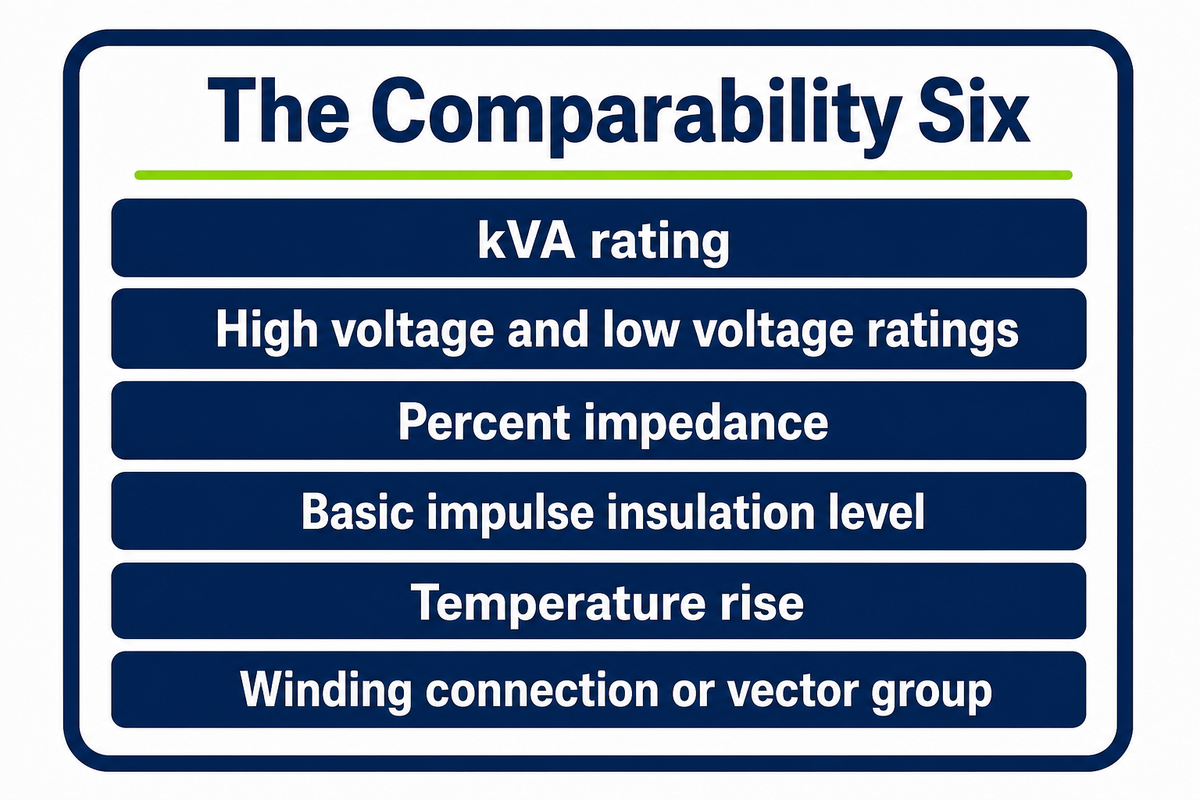
Six nameplate fields decide whether two transformer quotes are comparable: kVA rating, high voltage and low voltage ratings, percent impedance, basic impulse insulation level, temperature rise, and the winding connection or vector group. Everything else on the plate is useful; those six are the ones that make offers line up. What has to appear on the plate at all is not left to the manufacturer either: California Code of Regulations Title 8 section 2874 enumerates eleven information groups, from rated kVA, phases and frequency through tap voltages, connection diagram, polarity, impedance and temperature rise to the insulating medium and approximate total weight.
The Comparability Six
Photograph the plate on the unit you’re replacing and you have most of a request for quotation already. Below, each field is decoded with the consequence of leaving it open. Read the final column twice, because an unspecified field doesn’t become a default: it becomes a manufacturer’s choice, and different manufacturers choose differently.
| Nameplate field | What it fixes | If left blank in the RFQ |
|---|---|---|
| kVA rating | Continuous throughput at rated temperature rise | Nothing else can be quoted; every other field depends on it |
| High voltage rating | Primary winding voltage and tap arrangement | Supplier assumes a common feeder class; a tap mismatch is discovered at energization |
| Low voltage rating | Secondary winding voltage, for example 208Y/120 V or 480Y/277 V | Panel and feeder sizing downstream cannot be finished |
| Percent impedance | Fault current at the secondary and the ability to parallel | Two units that will not share load; protective device coordination has to be redone |
| Basic impulse insulation level | Withstand against lightning and switching surges | Supplier quotes the minimum for the voltage class; surge margin is silently lost |
| Temperature rise | Thermal headroom, commonly 65 °C average winding rise | Overload capability differs between offers that otherwise look identical |
| Winding connection / vector group | Delta or wye on each side, plus phase displacement | A unit that cannot be paralleled with the incumbent at all |
| Cooling class | Cooling method and any forced-air rating step | A fan-assisted rating is compared against a self-cooled one |
| Tested impedance and X/R | Measured values for the actual unit | Only design values are supplied; short-circuit study inputs stay approximate |
| No-load and load loss | The two loss components, in watts | Loss-capitalized bid comparison cannot be run |
| Frequency and date of manufacture | 60 Hz rating and unit age | Federal coverage itself depends on the 60 Hz rating |
Percent impedance carries more weight in power systems studies than its single line suggests. IEEE C57.12.00 clause 9.2 puts that tolerance at plus or minus 7.5 percent of the specified value for a two-winding transformer whose impedance voltage exceeds 2.5 percent, and, in restatements of the same clause, at plus or minus 10 percent at or below 2.5 percent and for three-winding, zigzag and autotransformer designs. Only the first of those two bands appears in a source read for this article. The clause is also reported to cap the spread between duplicate units at 7.5 percent, binding only where one manufacturer builds both in a single production run, so units bought from two suppliers, or from one supplier years apart, can sit at opposite edges of their own bands and still comply. Purchase specifications answer that by fixing impedance values themselves, and the tolerance is visible outside the standard: a Lawrence Livermore National Laboratory purchase specification sets a 5.75 percent target impedance for 750 to 3000 kVA units and repeats the same plus or minus 7.5 percent band above 2.5 percent nominal. One municipal specification reviewed for this article sets minimum impedance values by rating and states that units below them may be rejected. Tap position, meanwhile, is what a utility uses for voltage regulation along a long feeder, so the tap arrangement quoted has to suit the feeder the unit will sit on. Basic impulse insulation level gets its own treatment in Talite’s own basic impulse insulation level explainer.
Two comparability tests, and they use different fields
A quote is subject to two separate comparability questions, and buyers routinely answer the wrong one. Federal efficiency comparability turns on what 10 CFR 429.47(d) calls a kVA grouping: same kVA rating, same insulation type, same number of phases, and for medium-voltage dry-types the same basic impulse insulation level group rating. Electrical interchangeability turns on the six locked fields above. Because the federal grouping never looks at percent impedance or vector group, two units can share a kVA grouping, meet the same efficiency standard, and still refuse to parallel on your system.
Two comparability tests operate on one quote and they read different fields. Four fields decide a federal kVA grouping under 10 CFR 429.47(d); six decide whether a unit can replace the one already installed. Percent impedance appears in the second set and not the first, which is why federal equivalence is no promise of parallel operation.
No-Load Losses, Load Losses, and What They Cost Over Twenty Years
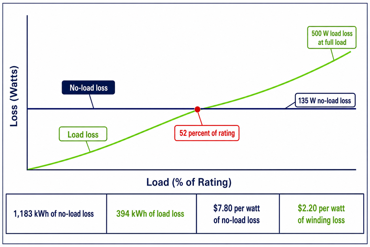
No-load loss is drawn continuously whenever a distribution transformer is energized, while load loss rises with the square of the load current. The nameplate fields decide which unit can replace another; the loss figures decide what the winner costs to run across a twenty-year life, and loading profile rather than rating settles that for any particular installation.
Two quotes for one kVA rating at different prices aren’t telling you which unit is cheaper. Core loss appears the moment the primary winding is energized and runs for all 8,760 hours of the year, load or no load; winding loss appears only when current flows. Halve the load and winding loss falls to a quarter, while no-load loss doesn’t move.
What Is the Difference Between No-Load Losses and Load Losses?
No-load loss, also called core or excitation loss, is spent magnetizing the core: hysteresis and eddy currents in the steel, released as heat regardless of load. Load loss is spent in the coil resistance and in stray losses in the conducting parts, and it tracks current squared.
Regulation defines the two the same way in 10 CFR 431.192, as losses incident to excitation and losses incident to a specified load carried. A lightly loaded unit is therefore a no-load-loss problem and a heavily loaded one a load-loss problem, and the same transformer can be both across a day.
Work it end to end on a published figure. Talite’s 50 kVA single-phase pad-mounted unit is published at 135 W no-load loss and 500 W load loss at full load. Load loss at a per-unit load p is 500 W multiplied by p squared, so the two components are equal when 500 p squared equals 135. That gives p as the square root of 0.27, which is 0.52. Below about 52 percent of rating, roughly 26 kVA on this unit, no-load loss is the larger of the two. Above it, load loss takes over.
Push it into energy. A feeder averaging 30 percent load draws 135 W for all 8,760 hours of the year, which is 1,183 kWh of no-load loss. Load loss at that point is 500 W multiplied by 0.30 squared, or 45 W, which over the same hours comes to 394 kWh. Three-quarters of the annual electrical energy lost by that transformer is spent before the first customer draws anything. Substitute your own loading and the arithmetic runs the same way; Talite’s own annual energy loss lookup does the hours for you.
Utilities put money on this directly. One municipal utility’s bid form evaluates offers as unit cost plus a loss evaluation, at $7.80 per watt of no-load loss and $2.20 per watt of winding loss. Applied to the 50 kVA figures above, 135 W of no-load loss at $7.80 capitalizes to $1,053 and 500 W of load loss at $2.20 to $1,100, adding $2,153 to the evaluated price of that unit. Comparing two such offers on sticker price alone discards the larger number.
Those factors come from one municipality’s bid dated 24 October 2018 against a specification revised in June 2014. They show that utilities monetize loss in the bid and weight no-load roughly three and a half times more heavily per watt. They are not current market values. Total owning cost, with its A and B factors, is worked through on Talite’s own total evaluated cost worksheet.
The 0.03 Percent Mass Cliff
Efficiency is bought with steel and copper, and the exchange rate is punishing at the top end. Adam Kotrba, a director at the copper industry’s own trade association, the Copper Development Association, reports modeling he presented at POWERGEN showing that even a 0.03 percent increase in distribution transformer efficiency, measured from the current federal standard to the future one, can produce a double-digit percentage increase in the mass and volume of the unit. The presentation itself was not obtained for this article, so treat the figure as indicative rather than as verified. One tenth of a percentage point on a datasheet becomes a different crate, a different crane and possibly a different pad.
Talite’s own published rating schedules show the same physics from the other end, and they run far above the covered range. Across its 110 to 220 kV schedule, no-load current falls from 0.6 percent at 6,300 kVA to 0.25 percent at 63,000 kVA. The absolute figures climb the other way: 10 kW no-load and 21,100 kg at 6,300 kVA, against 56.8 kW no-load and 71,800 kg at 63,000 kVA on a 6,970 mm frame. Short-circuit impedance holds at 10.5 percent across the eight rows. Those are power transformers, past the 34.5 kV and 5000 kVA limits of 431.192, so read them as the direction of the trade, not as distribution numbers. Efficiency is therefore a rigging, foundation and route-survey question as much as an energy one.
Two cautions belong with any loss number on a datasheet. One is a tolerance. Talite states that its quoted loss values follow the IEEE C57.12.00 tolerance of plus 10 percent on no-load loss and plus 6 percent on total loss, confirmed by C57.12.90 routine tests. That clause was not read for this article, so treat any published loss figure as a design value inside a band rather than as a measurement of your unit. Another is a certification point, and it sits in the regulation:
Efficiency must be determined either by testing, in accordance with 431.193, or by application of an AEDM that meets the requirements of 429.70.
An alternative efficiency determination method is a validated model, not a test of the unit in front of you. A certified efficiency figure and a published loss table are different artefacts, and neither measures the delivered transformer unless the nameplate carries tested values. Mechanical stress from cutting and assembling a core raises core loss permanently against the loss measured on the uncut material, which is one physical reason a modelled and an as-built figure can legitimately diverge.
One correction is owed to a claim that ranks well on this topic. One prominent page tells readers to expect 50 to 70 percent efficiency from a transformer, which is what you get if a load point is read as an efficiency value. Fifty to seventy percent is a credible number for how hard a unit is worked, not for how much of the energy it returns. Efficiency at lower loads does fall away from the peak, but the efficiency of typical distribution transformers runs between about 98 and 99 percent, a range carried in reference literature that credits it to De Keulenaer and colleagues at CIRED 2001 and to an ACEEE report. Neither primary was read for this article, so treat the range as indicative rather than as a verified figure. The 50 kVA schedule above agrees: 635 W of total loss at full load on 50,000 VA is 1.3 percent, on an IEC 60076-1 rating basis rather than the DOE Appendix A load points used elsewhere here.
Crossover between the two loss types on a 50 kVA unit published at 135 W and 500 W falls at 52 percent of rating. Below that point the transformer spends more energy as heat standing idle than it does carrying load, which is why a lightly loaded feeder rewards low core loss and a heavily loaded one rewards low winding loss.
The DOE Efficiency Rule: What Changed and When It Actually Bites
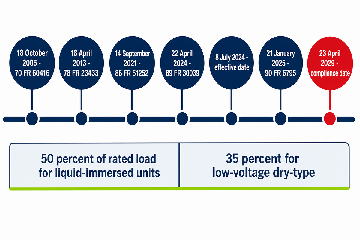
The United States Department of Energy issued revised distribution transformer efficiency standards as a final rule in April 2024. It took effect on 8 July 2024, with compliance required on and after 23 April 2029. Published secondary sources circulate two different compliance dates, and only the primary settles it.
The Compliance-Date Reconciliation
Search for the compliance date and you’ll be told 2027 by one class of source and 2029 by another. Neither cites the other, and none of them acknowledges that a disagreement exists. DOE’s own page states the position in two sentences. The effective date of the rule is 8 July 2024, and compliance is required on and after 23 April 2029. That’s the date to plan around. That 2027 figure appears to travel from earlier proposal-stage reporting which the final rule superseded.
Section 431.192 carries its own amendment chain, and reading it settles what changed when.
| Date | Citation | What it did |
|---|---|---|
| 18 October 2005 | 70 FR 60416 | Original definitions section |
| 18 April 2013 | 78 FR 23433 | Origin of the covered-equipment text still in force |
| 14 September 2021 | 86 FR 51252 | Test procedure and definitions amendment |
| 22 April 2024 | 89 FR 30039 | The final rule behind the 2029 compliance date |
| 8 July 2024 | Effective date | Rule in force; obligations begin to run |
| 21 January 2025 | 90 FR 6795 | Most recent amendment to the definitions section |
| 23 April 2029 | Compliance date | Units manufactured on and after this date must comply |
One further event needs stating precisely, because loose reporting of it has caused real confusion. On 9 September 2025, as required by the Congressional Review Act and Pub. L. 119-8, the Department of Energy removed amendments in both Part 429 and Part 431 that had taken effect on 23 December 2024. What came out was that October 2024 amendment package, not the April 2024 efficiency rule: section 429.47 shows no change to its content after January 2017, and the efficiency levels themselves stand in Part 431. A further step is open. On 15 June 2026 the Department published a Request for Information (91 FR 35903) reopening these standards, citing a Presidential Determination under section 303 of the Defense Production Act and Executive Order 14156. The 2029 date stands as written; whether it survives that review is not settled.
Efficiency levels are measured at a fixed per-unit loading. That loading is written into the notes to the section 431.196 efficiency tables, and it uses the per-unit load the rule’s uniform test method defines. It isn’t one number: 50 percent of rated load for liquid-immersed units, 50 percent for medium-voltage dry-type, and 35 percent for low-voltage dry-type. Energy conservation targets are set at that one point, while your transformer sees whatever the feeder gives it. Transformers are designed against that fixed assumption rather than against a particular feeder duty cycle. This is the structural reason a unit can be fully compliant and still be the wrong choice for a particular load profile, and it’s a matter of regulation rather than of any manufacturer’s design.
Effective 8 July 2024 and biting on 23 April 2029, the rule evaluates its efficiency levels at 50 percent load for liquid-immersed and medium-voltage dry-type units, and at 35 percent for low-voltage dry-type alone. Specifications written today have roughly two and a half years of design lead before that date governs what may be manufactured.
Why Distribution Transformer Specifications Now Freeze Earlier in the Project

The binding constraint on a distribution transformer purchase has moved from price to schedule. A medium-voltage unit can take the better part of a year to arrive. Its electrical specification must therefore be frozen before the civil and layout design is finished, which inverts the order most project plans still assume.
Reordering is the actionable change here, and everything below supports it rather than leading. Congressional Research Service report R48933 records a two-year wait for distribution transformers in 2024 and relays a consultancy’s estimate that the wait had fallen to about 30 weeks by the second quarter of 2025. Build-slot quotations for 2026 from one contractor, Terrapin Construction Group, reported in the National Law Review, put pad-mounted distribution units at 40 to 65 weeks; that is a single contractor’s own scheduling statement rather than a survey. The 128-week and 144-week figures that dominate coverage describe power transformers and generator step-up units, not this class. A procurement item with a 40-week lead time can’t wait for the pad drawing. Its kVA rating, voltage ratings, impedance, basic impulse insulation level and vector group have to be settled while the building is being laid out. The pad is then designed around the transformer rather than the other way round.
Cost moved as well, for a traceable reason. Congressional Research Service analysis of producer price data records that prices of both distribution transformers and large power transformers rose roughly 40 percent between 2020 and 2024 on an inflation-adjusted basis, and that the Department of Energy found the rise correlated with the price of grain-oriented electrical steel from 2021. Core steel is the constraint, which is why material choice reads as a procurement variable. Other market analyses use different baseline years and nominal figures and report larger increases; those numbers aren’t interchangeable with this one and must not be averaged with it.
Demand is the other half. Preliminary National Renewable Energy Laboratory analysis, published by the Department of Energy’s Office of Electricity, puts the installed United States stock at 60 to 80 million units carrying upwards of 3 TW of capacity. Fleet age comes from elsewhere: a 2024 Department of Energy study, reported by the commercial research firm Wood Mackenzie, put 55 percent of installed units at more than 33 years old. The same preliminary analysis projects stock capacity growth of up to 160 to 260 percent on 2021 levels by 2050 as electrification and renewable energy interconnection expand. Replacement of an aging fleet and growth in new connections draw on the same factory slots, and the power grid needs both at once.
How Long Does a Distribution Transformer Last?
Service life is set by insulation aging rather than by wear, and thermal history is what consumes it. A conventionally loaded liquid-immersed unit is commonly planned around three to four decades in utility practice, a range this article did not verify against a primary source.
The 2024 Department of Energy study cited above describes those units, at more than 33 years old, as well beyond their expected service life, which is a statement about a population rather than about failures. Sustained loading above nameplate and high ambient temperatures shorten it, while a lightly loaded unit in a temperate location can exceed it. Long service life is a consequence of thermal history rather than of construction quality alone. IEEE C57.91, current edition 2025, is the loading guide that quantifies the trade between overload and insulation aging, and it’s the document to consult before planning a deliberate overload.
Scheduling consequences are concrete: if the transformer takes 40 weeks and its specification depends on a load study, that load study is now on the critical path of the electrical distribution design. Reliable power delivery on the commissioning date is decided by when the study is commissioned, not by how quickly the order is placed.
Distribution transformer lead times peaked near two years in 2024 and were estimated at about 30 weeks by the second quarter of 2025, while a single contractor’s own 2026 slot quotations ran 40 to 65 weeks. Even the improved figure moves the transformer specification to the front of the project schedule. Freezing kVA, voltage ratings and impedance early is now a scheduling decision rather than a technical preference, because the civil design has to follow the equipment instead of preceding it.
Getting a Comparable Quote: The Fields That Must Be Fixed First
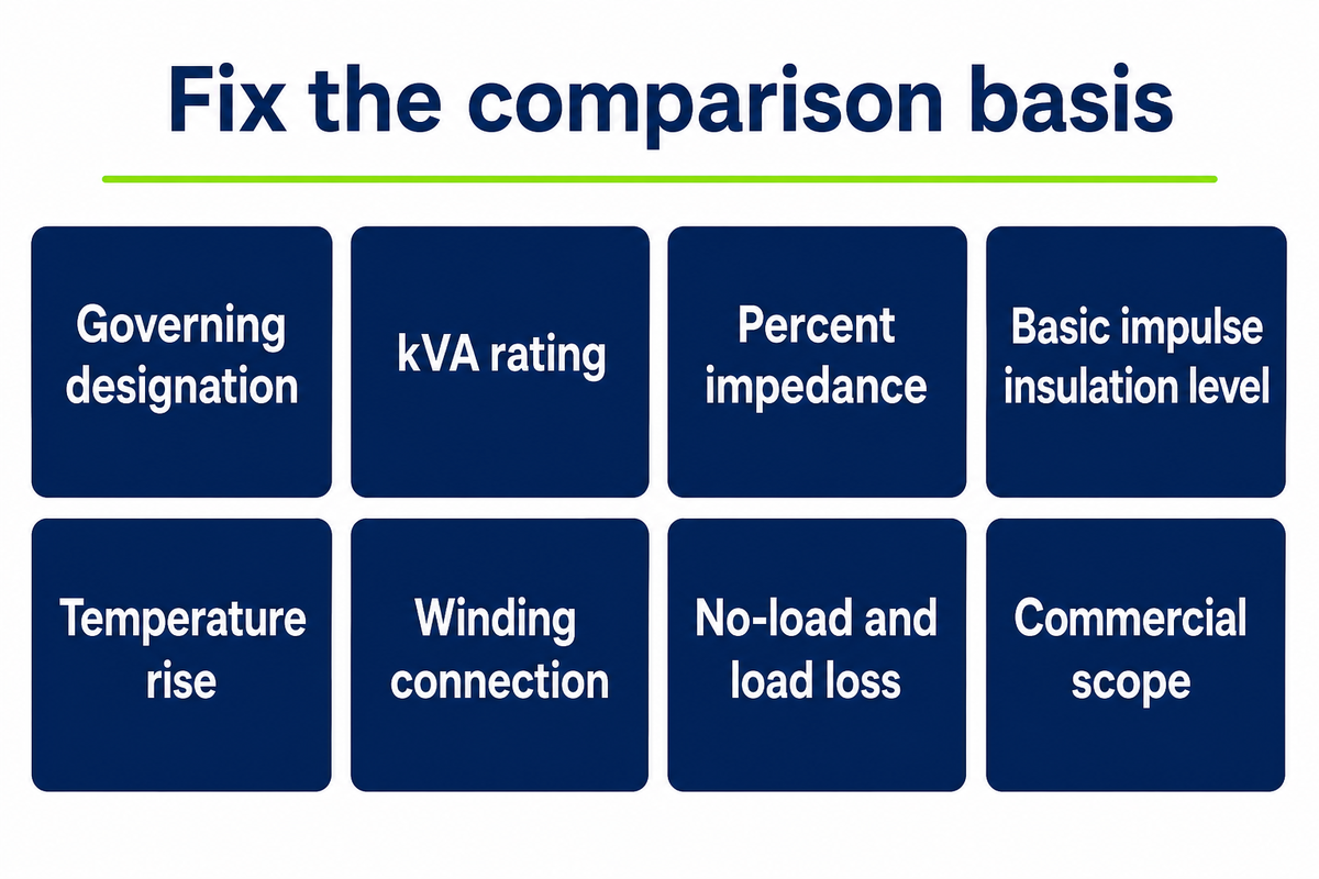
Comparable offers require the buyer to fix the fields that decide comparability before the quotes are issued. Freezing kVA, voltage ratings and impedance early only pays off if the request itself invites comparison. Fix the governing designation, the Comparability Six and the commercial scope, and three offers line up side by side. Leave them open and each supplier answers a slightly different question. No single field set is mandatory: the Department of Energy Office of Electricity webinar put the count at roughly eighty thousand configurations across ten attributes, with the plain observation that every utility still writes its own requirements, which is exactly why the buyer has to fix the comparison basis.
In practice this comes down to the two comparability tests from the nameplate section. Suppliers can offer a unit that shares your incumbent’s federal kVA grouping, meets the same efficiency standard, and still won’t parallel with it. Naming impedance and its tolerance in the request closes that gap. Copy the table below into a quote request, and Talite’s own request for quotation completeness scorer will tell you which fields are still open.
RFQ checklist — copy these into your quote request:
| Parameter | Recommended range | Why it matters | How to verify |
|---|---|---|---|
| Governing designation | Name the C57 number and state whether an edition is fixed or the latest revision applies | Decides which fields exist before any value is set | Designation cited on the offer drawing and the nameplate |
| kVA rating | 10–5000 kVA liquid-immersed; 15–5000 kVA dry-type | Sets federal coverage and every downstream field | Nameplate plus certification report if covered |
| Percent impedance | State target value and cite the clause 9.2 tolerance that actually applies: plus or minus 7.5 percent above 2.5 percent impedance, plus or minus 10 percent at or below; match the incumbent’s tested value if paralleling | Decides fault current and whether units share load | Tested impedance on the nameplate, not a design value |
| Basic impulse insulation level | Specify explicitly for the voltage class rather than accepting the minimum | Surge withstand margin is otherwise quoted away | Impulse test report per the applicable test code |
| Temperature rise | 65 °C average winding rise unless a different class is intended | Sets thermal headroom and overload behavior | Temperature rise test report |
| Winding connection | State both sides and the phase displacement | Wrong group cannot be paralleled at all | Connection diagram on the nameplate |
| No-load and load loss | Request guaranteed values in watts, with the tolerance stated | The only way to run a loss-capitalized comparison | Routine loss test report per C57.12.90 or C57.12.91 |
| Commercial scope | List tests, bushings, accessories, delivery terms and offloading responsibility | Changes what a price includes more than any electrical field | Line-item scope on the quotation |
Two conditions change what has to be hard-specified. If the unit will parallel with an existing transformer, impedance and vector group become pass or fail criteria and the incumbent’s tested values are the reference. If the unit is federally covered, the efficiency level isn’t yours to negotiate and certification is the supplier’s obligation. The useful question becomes which fields the standard leaves open. Where neither holds, impedance and cooling class can be left to the manufacturer with a stated acceptance range.
Suppliers who publish per-rating loss schedules, impedance ranges and mass and envelope data make this comparison possible before an enquiry is even sent. Talite publishes eight rating schedules spanning its distribution transformer range and its power transformer range; the three-phase pad-mounted schedule runs from 45 to 7500 kVA at impedances of 2.8 to 5.75 percent. Once the field set is fixed, a review of Talite’s own page on distribution transformer manufacturers is a reasonable next step.
A published guide doesn’t replace the requirements of the serving utility or the judgement of a qualified engineer with responsibility for the installation. Utility interconnection rules, local codes and the approved design govern, and they may impose requirements beyond anything described here.
Frequently Asked Questions
Where does a distribution transformer sit in the chain?
Power transformers and distribution transformers differ by position and by loading rather than by principle. Power transformers sit between generation and transmission or at a substation, operate above 34.5 kV, and run near full load for long periods. Distribution transformers perform the last step down to 600 V or less and spend most of their life lightly loaded.
That loading difference drives the design difference. Power transformers built for sustained heavy load are optimized around load loss; a distribution transformer sitting at 20 to 40 percent load most of the day is dominated by no-load loss, which is why core material matters more in the second case. Talite’s own page on types of power transformers used in transmission and distribution covers a separate subject from the last-step units described here.
How does a distribution transformer work?
Alternating current in the primary winding creates a changing magnetic field in the core, and that field induces a voltage in the secondary winding. Turns ratio between the two windings sets the ratio of voltages, so stepping down the voltage is a matter of winding fewer turns on the secondary side.
No moving parts are involved. Flux passes between primary and secondary through the core, and the two windings are electrically separate but magnetically coupled. A three-phase unit repeats the arrangement on three legs of a common core, which is why one machine with three secondary windings is more compact than three single-phase units of the same total rating.
What applications are distribution transformers best suited for?
Any application taking a medium-voltage feeder down to utilization voltage falls in range: residential subdivisions, commercial buildings, light industrial sites, campuses, data centers and renewable energy interconnections. Federal coverage starts at 10 kVA for liquid-immersed units and 15 kVA for dry-type and runs to 5000 kVA; a 5 kVA pole-mounted unit is a distribution transformer in engineering terms but sits below that covered class.
Selection within that range follows site constraints rather than application labels. Indoor installations with fire loading limits push toward dry-type units, outdoor pads and higher ratings toward liquid-immersed, and overhead service toward pole-mounted construction. A power supply transformer serving sensitive electronic load may add harmonic or K-factor requirements to the standard field set.
How do I know whether my transformer is covered by the DOE efficiency rule?
Check four conditions and thirteen exclusions. It must have an input line voltage of 34.5 kV or less, an output of 600 V or less, a 60 Hz rating, and a capacity of 10 to 5000 kVA liquid-immersed or 15 to 5000 kVA dry-type. Any one of the thirteen named exclusions removes it.
Read the exclusions carefully against your own specification. A tap range of 20 percent or more, a sealed or nonventilated construction, or a grounding duty each take the unit outside the rule, and those are specification choices rather than accidents of design.
Are dry-type and oil-immersed distribution transformers held to the same efficiency levels?
No. Standards are set separately by equipment class, and the assumed loading differs too: efficiency is evaluated at 50 percent of rated load for liquid-immersed and medium-voltage dry-type units, but at 35 percent for low-voltage dry-type. Medium-voltage dry-types are further divided by basic impulse insulation level group.
That grouping matters when comparing offers. Under 10 CFR 429.47(d), a federal kVA grouping is defined by kVA rating, insulation type, phase count and, for medium-voltage dry-types, BIL group rating, so a dry-type and a liquid-immersed unit of identical rating are never in the same grouping.
What kVA rating should I specify?
Size against the calculated connected load with a documented growth allowance, not against the rating of whatever is installed now. Oversizing raises no-load loss for the whole service life; undersizing consumes thermal headroom and shortens insulation life. Neither error announces itself until the unit has been energized for a season.
Arithmetic and load-factor assumptions are worked through in Talite’s own kVA sizing guide.
Can these transformers be digitally monitored?
Yes. Winding and top-oil temperature, load current and, on liquid-immersed units, dissolved gas can all be instrumented, and monitoring is normally specified as an accessory package rather than as part of the transformer designation itself. Nothing in the governing C57 designation prevents it.
Specify the sensor set, output protocol and enclosure penetrations in the commercial scope of the request, because these are the items most likely to differ silently between two otherwise comparable offers.
What This Guide Is Built From
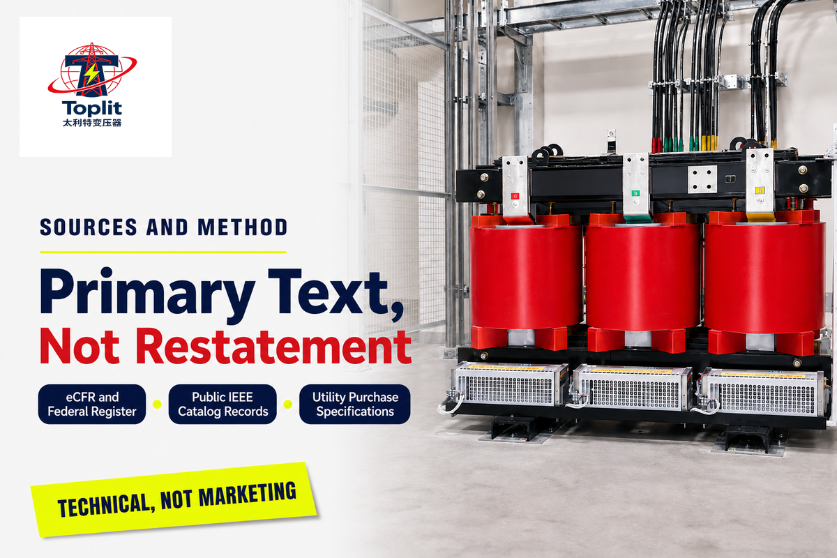
Every federal regulatory figure here was read from the eCFR or Federal Register primary text rather than from a secondary restatement, and one number that appears throughout the published literature didn’t survive that check. IEEE clause content is cited from public catalog records and utility purchase specifications. Where sources disagreed, as on the compliance date and the size of the recent price rise, the disagreement is stated rather than averaged.
Scope figures commonly given as 10 to 833 kVA single-phase and 15 to 2,500 kVA three-phase aren’t in 10 CFR 431.192: the section divides by insulation type at a 5000 kVA ceiling, and 833 kVA belongs to an impedance table inside one of the exclusions.
Product data and company information attributed to Talite come from the company’s own published rating schedules and corporate materials, and are first-party information rather than independent verification. Talite Transformer Co., Ltd. has worked in the power equipment sector for over three decades. Originally established as Jiangsu Fangteng Industrial Co., Ltd., the company operates from the Hai’an Economic and Technological Development Zone in Nantong, Jiangsu Province, integrating research, production and sales.
Bring a fixed field set, not a rating
Send the governing designation, the Comparability Six and your loss evaluation basis, and offers can be compared line by line. Talite can quote against that field set without displacing your utility’s requirements or your responsible engineer.
References & Sources
- 10 CFR 431.192, Distribution Transformer Definitions Electronic Code of Federal Regulations
- 10 CFR 431.196, Energy Conservation Standards and Effective Dates Electronic Code of Federal Regulations
- 10 CFR 429.47, Distribution Transformers Certification and kVA Groupings Electronic Code of Federal Regulations
- Distribution Transformers, Effective and Compliance Dates U.S. Department of Energy
- 78 FR 23433, Energy Conservation Standards for Distribution Transformers Federal Register
- Electric Grid Transformers: Supply Chain Issues Congressional Research Service
- R&D Efforts to Address Transformer Supply Chain Issues U.S. Department of Energy, Office of Electricity
- IEEE C57.12.00, General Requirements for Liquid-Immersed Distribution, Power and Regulating Transformers IEEE Standards Association
- IEEE C57.12.34-2022, Three-Phase Pad-Mounted Distribution Transformers IEEE Standards Association
- IEEE C57.91-2025, Loading Guide for Liquid-Immersed Transformers IEEE Standards Association
- Energy Conservation Program: Distribution Transformers, Request for Information (15 June 2026) Office of Energy Efficiency and Renewable Energy
- Distribution Transformer Webinar, text alternative U.S. Department of Energy, Office of Electricity
- Specification PEL-E-261219, Pad-Mounted Distribution Transformers Lawrence Livermore National Laboratory
- California Code of Regulations Title 8, Section 2874, Transformer Nameplates California Department of Industrial Relations
- How DOE Efficiency Standards Could Reshape the U.S. Transformer Market Copper Development Association
- Specification for Three Phase Pad-Mount Distribution Transformers, T-5 City of Healdsburg, California
- The Grid’s Bottleneck Isn’t Just Money, It’s Materials National Law Review, source of the contractor build-slot lead times
Sources accessed September 4, 2026.
![Pad-Mounted Transformer: How It Works [2026 Guide]](https://toplit-transformer.com/wp-content/uploads/2026/08/pad-mounted-transformer-guide-featured-150x150.png)

![Single Phase Pad Mounted Transformer Guide [2026]](https://toplit-transformer.com/wp-content/uploads/2026/08/single-phase-pad-mounted-transformer-guide-featured-1-150x150.png)