Get in touch with Talite Transformer Co., Ltd Company

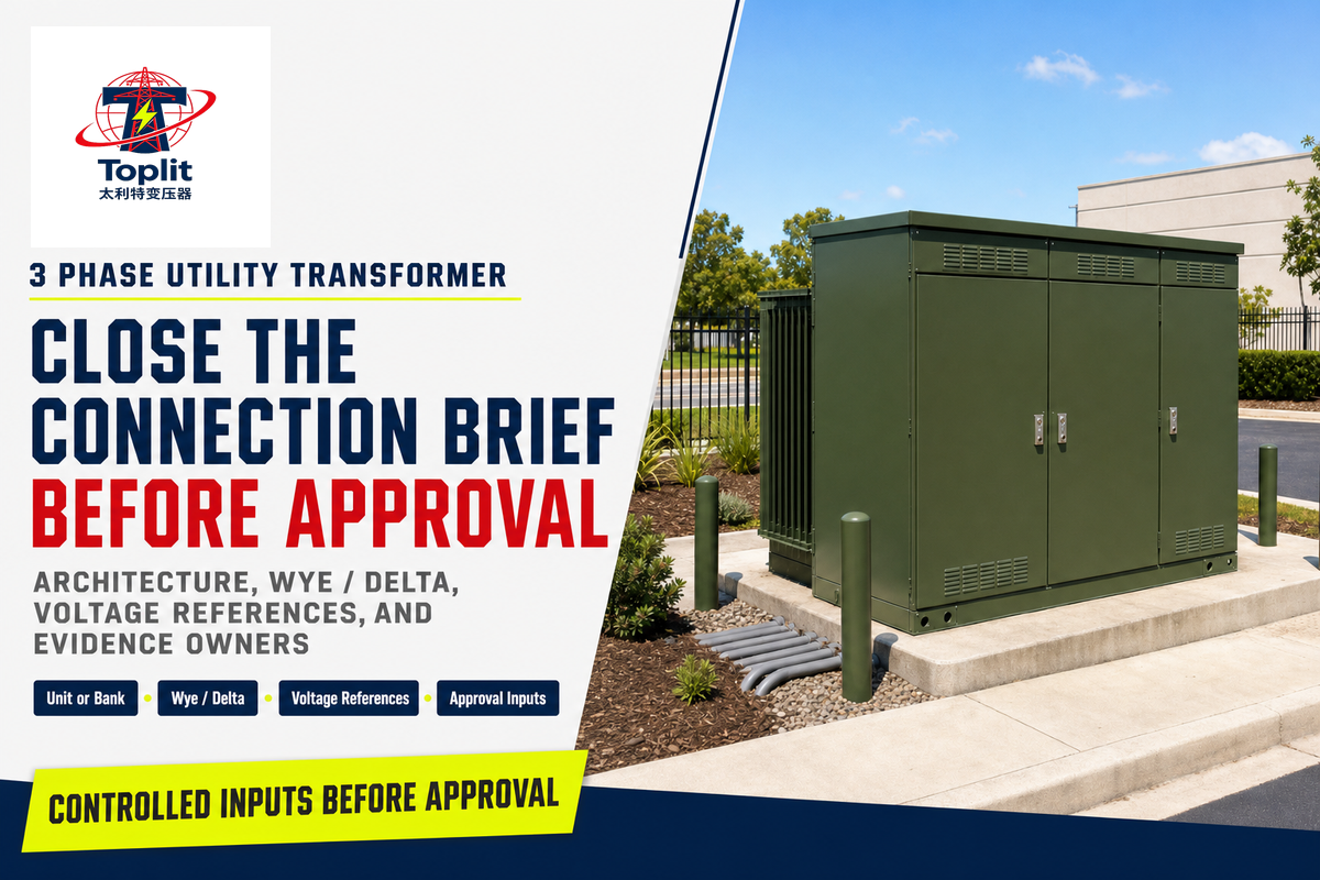
A 3 phase utility transformer is electrical equipment that changes voltage between three-phase circuits for a defined utility or utility-connected duty. In an ideal three-phase system, corresponding phase quantities are separated by 120 degrees. “Three phase” identifies the electrical system, but it does not settle the unit-or-bank architecture, rated voltages, winding connection, neutral, grounding, mounting interface, or approval responsibility.
Known from the phraseThe source and load use a three-phase system.Still to confirmArchitecture, kVA load basis, rated voltage references, frequency, connection, grounding, mounting, studies, drawings, tests, and responsible approvers.
This guide helps buyers turn an incomplete label into reviewable project inputs. It explains document boundaries and common relationships, but it is not a field wiring guide, protection study, grounding design, or engineering approval.
Quick orientation
- Architecture and connection are separate decisions.
- Line-to-line and line-to-neutral values must be labeled.
- A generic diagram cannot release field work.
- Every open field needs an owner and a controlling document.
Updated August 2026. Confirm the current utility rules, adopted standards, drawing revisions, and project requirements when the specification is issued.
Which Connection Details Does “3 Phase Utility Transformer” Leave Open?
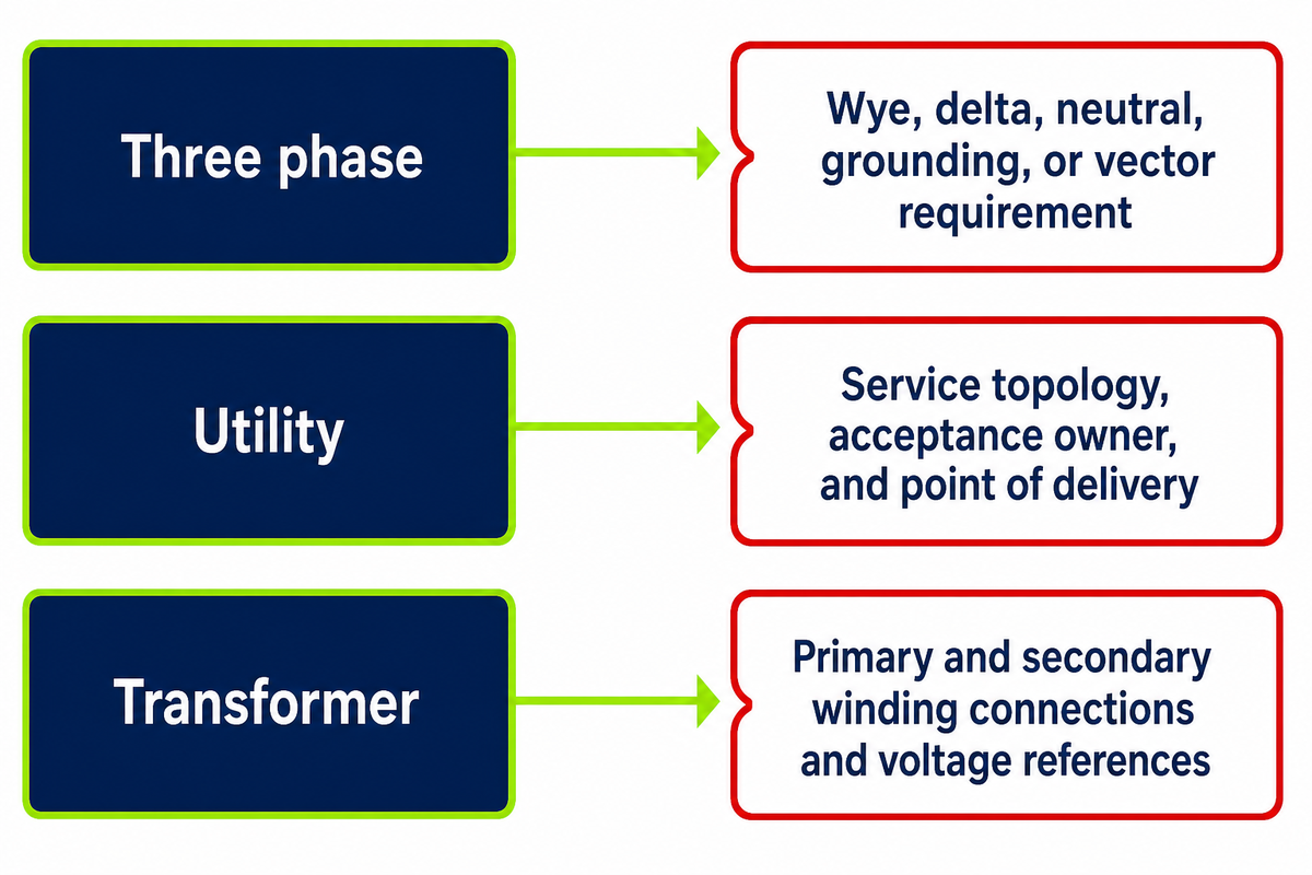
The phrase 3 phase utility transformer identifies a three-phase voltage-transformation duty, but it does not specify unit-or-bank architecture, primary or secondary winding connection, line-to-line and line-to-neutral references, neutral treatment, grounding, or phase displacement. Those connection fields must come from controlled utility and project documents.
| Phrase element | What it establishes | Connection detail that remains open |
|---|---|---|
| Three phase | A polyphase circuit context | Wye, delta, neutral, grounding, or vector requirement |
| Utility | A utility or utility-connected duty in everyday language | Service topology, acceptance owner, and point of delivery |
| Transformer | Voltage transformation by electromagnetic induction | Primary and secondary winding connections and voltage references |
A magnetic core and winding coil help explain voltage transformation by electromagnetic induction, but this article uses that concept only to frame connection questions. For grid role, power distribution context, construction, and general transformer design terminology, use the electric utility transformer overview.
Search-language boundary
Terms such as step-down, three sets of windings, core material, dielectric, large transformers, electrical power distribution, industrial power distribution, and power generation belong to other selection dimensions. They are research prompts, not connection specifications. Equipment class, mounting, high voltage and low voltage ratings, and governing requirements stay in controlled documents and outside this connection comparison.
Terms such as step-down, three sets of windings, core material, dielectric, large transformers, electrical power distribution, industrial power distribution, and power generation belong to other selection dimensions. They are research prompts, not connection specifications. Equipment class, mounting, high voltage and low voltage ratings, and governing requirements stay in controlled documents and outside this connection comparison.
“is designed for operation with an input line voltage of 34.5 kV or less”
The quoted line belongs to a U.S. federal energy-conservation definition that also uses an output threshold of 600 V and 60 Hz operation. It is a program boundary with explicit exclusions, not a global definition of every transformer used by a utility and not proof that any particular Talite product falls inside the regulated class.
Keep scopes separate
The federal example combines an input boundary of 34.5 kV, an output boundary of 600 V, and operation at 60 Hz. Project references such as 480 V, 277 V, or 120 V describe a different document layer and never establish federal coverage by themselves.
The federal example combines an input boundary of 34.5 kV, an output boundary of 600 V, and operation at 60 Hz. Project references such as 480 V, 277 V, or 120 V describe a different document layer and never establish federal coverage by themselves.
Procurement objection resolved
If an internal request says only “three phase,” return it for the source topology, primary and secondary voltage references, unit-or-bank architecture, winding connections, neutral treatment, grounding, vector requirement, and governing documents before comparing offers.
If an internal request says only “three phase,” return it for the source topology, primary and secondary voltage references, unit-or-bank architecture, winding connections, neutral treatment, grounding, vector requirement, and governing documents before comparing offers.
Three Phase Transformer Configuration: One Unit or Three Single-Phase Transformers?
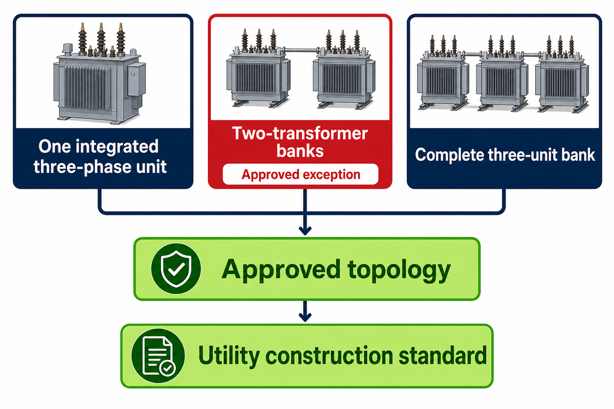
One integrated assembly or a bank of single-phase transformer units can provide a three phase transformer architecture, but that split is only a first routing screen. Utility practice, one-line drawings, replacement strategy, ratings, and installation interfaces decide which architecture can enter a project review. Whether one transformer or several units are proposed, the approved documents govern the topology.
Unit-or-Bank Configuration Fork
The Unit-or-Bank Configuration Fork separates the first architecture question without pretending to select equipment.
One integrated three-phase unit
- One equipment identity and assembly
- Common enclosure and installation interface
- Ratings and connection come from one controlled data set
- Replacement scope follows the complete assembly
Complete three-unit bank
- Three separate single-phase units form the bank
- Each unit and bank arrangement need identification
- Interconnections must match the approved drawings
- Replacement strategy must preserve bank compatibility
The fork is not exhaustive. EPRI documents open-wye/open-delta arrangements using two single-phase transformers, including three-wire and center-tapped four-wire variants; such incomplete-bank topologies require the utility’s approved design and cannot be treated as a routine substitute.
Architecture exception
Two-transformer banks fit neither the integrated-unit column nor the complete three-transformer column. Record the arrangement explicitly, including the approved topology, ratings, neutral arrangement, expected loading, and operating constraints.
Two-transformer banks fit neither the integrated-unit column nor the complete three-transformer column. Record the arrangement explicitly, including the approved topology, ratings, neutral arrangement, expected loading, and operating constraints.
Can three single-phase transformers replace a 3 phase transformer?
Three single-phase units can form a three-phase bank when the utility and responsible engineer approve the bank topology, unit ratings, voltage relationships, polarity, phase sequence, connection, neutral, grounding, protection, and physical interfaces. Matching only the kVA total or voltage labels does not establish equivalence.
Release boundary
Replacement proposals stay open until the current one-line diagram, utility construction standard, bank schedule, unit data, and protection study all identify the same arrangement.
Replacement proposals stay open until the current one-line diagram, utility construction standard, bank schedule, unit data, and protection study all identify the same arrangement.
Buyers may compare replacement granularity and document burden, but should not assume that either architecture is more efficient, cheaper, faster, or more reliable without project evidence. The practical objection is missing approval: if the arrangement is absent from the utility standard and one-line, procurement has no auditable basis to release it.
Evidence capsule
EPRI’s two-transformer model includes three-wire and 4-wire forms, which makes a 2-unit exception material during architecture review. The model is technical counterevidence, not a universal operating recommendation or a Talite configuration claim. The IEEE transformer terminology page supplies a standards vocabulary reference, not project topology approval.
EPRI’s two-transformer model includes three-wire and 4-wire forms, which makes a 2-unit exception material during architecture review. The model is technical counterevidence, not a universal operating recommendation or a Talite configuration claim. The IEEE transformer terminology page supplies a standards vocabulary reference, not project topology approval.
Three Phase Transformer Connections: Delta vs Wye Winding Requirements
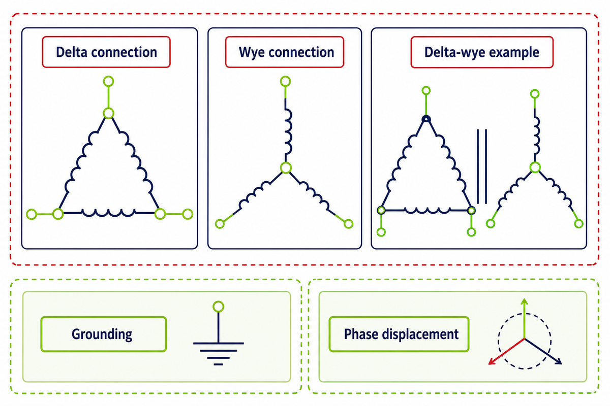
Delta and wye describe common ways to connect three windings, yet neither word completes a three phase transformer connection specification. Source topology, rated line voltage, phase voltage, neutral treatment, grounding, phase displacement, fault behavior, and protection requirements remain controlled inputs.
| Connection label | What it establishes conceptually | What remains open |
|---|---|---|
| Delta connection | Windings form a closed loop; line voltage equals winding phase voltage in the ideal relationship | Grounding, phase displacement, taps, fault duty, and protection |
| Wye connection | One end of each winding meets at a common point; line voltage is √3 times phase voltage in a balanced ideal relationship | Whether the neutral is brought out, grounded, loaded, or permitted |
| Delta-wye or wye-delta | Different primary and secondary winding families | Required phase displacement, grounding path, and vector notation |
What is the difference between Delta and Wye connections?
Delta connections join three windings end-to-end in a loop, while wye connections join one end of each winding at a common point. In an ideal balanced wye system, a 480 V line-to-line value corresponds to about 277 V line-to-neutral; a 208 V line-to-line value corresponds to about 120 V line-to-neutral. The relationship between line current and phase current also depends on the connection, while voltage between a line and the neutral requires an accessible neutral.
Relationship, not selection
The √3 relationship and 120 electrical-degree phase spacing explain reference values. They do not authorize a vector group, neutral loading, conductor arrangement, grounding method, or protection setting for a project.
The √3 relationship and 120 electrical-degree phase spacing explain reference values. They do not authorize a vector group, neutral loading, conductor arrangement, grounding method, or protection setting for a project.
IEEE C57.105’s public scope reaches grounded and ungrounded delta/wye combinations, T-connected, zigzag, and special connections. That broader vocabulary is why “delta vs wye” should be treated as connection literacy, not an exhaustive taxonomy or a substitute for the approved one-line diagram.
Procurement objection resolved
Copied connection words cannot answer whether the neutral is available, which phase displacement is required, how grounding is arranged, or which protective study applies. Keep the request open until those fields and their controlling revisions agree.
Copied connection words cannot answer whether the neutral is available, which phase displacement is required, how grounding is arranged, or which protective study applies. Keep the request open until those fields and their controlling revisions agree.
Search demand for delta or wye diagrams says that readers need clearer explanations; it does not reveal which connection is correct for a given electric power system. Selection remains a utility and engineering decision tied to source conditions, load behavior, standards, and approved documents.
Evidence capsule
Two numeric relationships organize the review: phase quantities are separated by 120°, and a balanced wye line-to-line voltage is √3 times line-to-neutral voltage. Neither relationship supplies project approval, fault duty, or a permissible grounding scheme.
Two numeric relationships organize the review: phase quantities are separated by 120°, and a balanced wye line-to-line voltage is √3 times line-to-neutral voltage. Neither relationship supplies project approval, fault duty, or a permissible grounding scheme.
Use the Four-Field Voltage Reference Card
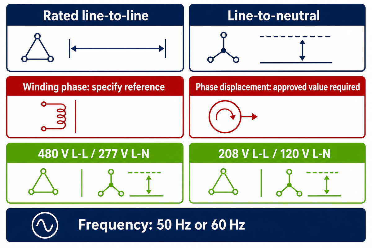
The Four-Field Voltage Reference Card records which voltage each number describes before anyone checks a configuration. Write the line-to-line rating, any line-to-neutral requirement, the winding-phase reference where relevant, and the required phase displacement or vector notation; mark unknowns instead of inferring them.
1. Rated line-to-line
State primary and secondary system values with units.
State primary and secondary system values with units.
2. Line-to-neutral
Record the required value and whether a neutral is available.
Record the required value and whether a neutral is available.
3. Winding phase
Identify the winding reference only when the drawing or calculation needs it.
Identify the winding reference only when the drawing or calculation needs it.
4. Phase displacement
Copy the approved vector or displacement requirement exactly.
Copy the approved vector or displacement requirement exactly.
Requests that state “480/277 V” communicate both line-to-line and line-to-neutral references when the context is a compatible wye system. Bare “480 V” wording does not say whether a neutral is required, while “120 V” without a reference can be misread as a line value, a phase value, or an auxiliary circuit.
Do
- Label every voltage with its reference
- Copy approved vector notation exactly
- Mark unknown neutral treatment as open
- Attach the one-line drawing revision
Don’t
- Infer connection from one voltage pair
- Convert examples into project ratings
- Choose phase displacement from a web diagram
- Assume a common point is an approved neutral
The card is a document-control tool, not a calculator. Even when the ideal √3 relationship reproduces a familiar value, the approved drawing must still establish the actual connection, nominal system ratings, taps, grounding, tolerance, and equipment duty.
How to label examples
Write 480 V L-L / 277 V L-N or 208 V L-L / 120 V L-N, and state 50 Hz or 60 Hz separately. Converting 1 kV to 1,000 V changes notation, not the approved system rating.
Write 480 V L-L / 277 V L-N or 208 V L-L / 120 V L-N, and state 50 Hz or 60 Hz separately. Converting 1 kV to 1,000 V changes notation, not the approved system rating.
Procurement objection resolved
If an RFQ contains one unlabeled voltage pair, return it with four explicit fields. Suppliers cannot reliably compare primary and secondary windings when the line and phase references are mixed.
If an RFQ contains one unlabeled voltage pair, return it with four explicit fields. Suppliers cannot reliably compare primary and secondary windings when the line and phase references are mixed.
The public University of Maryland Division 26 specification shows why the fields travel together: its project-specific records include transformer kVA, primary and secondary voltages, connection, impedance, taps, and phase shift. Those are examples of handoff fields, not universal values or Talite product data.
Evidence capsule
The card separates 4 voltage and phase references before review. A 480 V line value, 277 V neutral value, and 120° phase relationship can coexist conceptually, but only the controlled project drawing assigns them to a real circuit.
The card separates 4 voltage and phase references before review. A 480 V line value, 277 V neutral value, and 120° phase relationship can coexist conceptually, but only the controlled project drawing assigns them to a real circuit.
What a 3-Phase Transformer Connection Diagram Can and Cannot Tell You
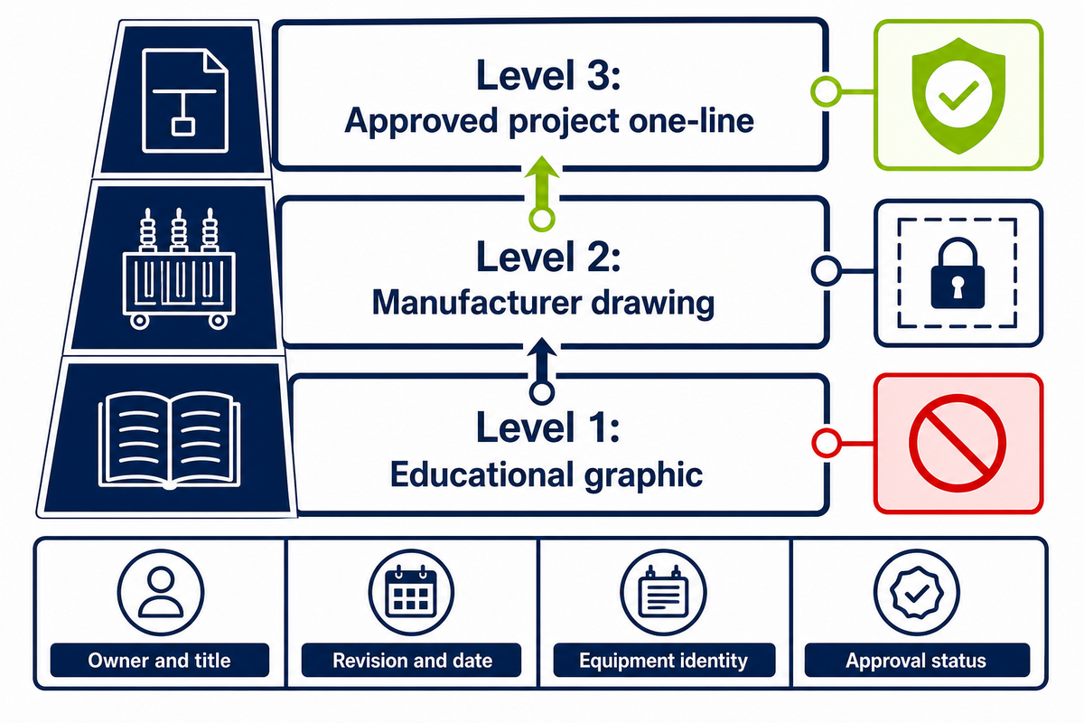
Connection diagrams for a 3-phase transformer can show labeled windings, terminals, voltage references, phase notation, and intended interconnections within their stated scope. The drawing cannot authorize field work unless its owner, title, revision, ratings, approval status, and relationship to the project one-line are controlled.
Level 1: Educational graphic
Explains a concept; no project authority.
Explains a concept; no project authority.
Level 2: Manufacturer drawing
Controls the identified equipment within its revision and scope.
Controls the identified equipment within its revision and scope.
Level 3: Approved project one-line
Records the accepted system relationship and approval chain.
Records the accepted system relationship and approval chain.
Buyers can check whether the drawing names the primary winding, secondary winding, rated values, phase, terminal labels, connection notation, taps, and revision. Missing revisions or unmatched equipment identities are document-control failures even when the circuit looks familiar.
| Check | Visible evidence | Route if absent |
|---|---|---|
| Owner and title | Issuing organization and drawing purpose | Document controller |
| Revision and date | Current approved revision | Responsible engineer |
| Equipment identity | Matching tag or data reference | Supplier and owner |
| Approval status | Approved-for-purpose status | Utility or project approver |
How to wire up a 3-phase transformer?
Generic articles cannot safely provide project wiring steps. Qualified and authorized personnel must work from the approved one-line, manufacturer connection drawings, utility rules, grounding design, protection study, conductor and termination design, isolation procedures, test plan, and site safety controls for any installation.
Document review is not installation
Buyers may identify missing labels, revisions, values, and approvals. They should not derive conductor sizing, field terminations, switching steps, protective settings, arc-flash controls, or energization instructions from this page.
Buyers may identify missing labels, revisions, values, and approvals. They should not derive conductor sizing, field terminations, switching steps, protective settings, arc-flash controls, or energization instructions from this page.
Search-document boundary
Queries such as “3 phase utility transformer wiring diagram,” “3 phase utility transformer diagram,” and “three-phase transformer connections PDF” express demand for drawings. Searches for “turns on the primary,” “turns on the secondary,” “power transfer,” or “power delivered” are also vocabulary prompts, not project ratings or conversion instructions. These queries do not establish approval, revision control, or field authority.
Queries such as “3 phase utility transformer wiring diagram,” “3 phase utility transformer diagram,” and “three-phase transformer connections PDF” express demand for drawings. Searches for “turns on the primary,” “turns on the secondary,” “power transfer,” or “power delivered” are also vocabulary prompts, not project ratings or conversion instructions. These queries do not establish approval, revision control, or field authority.
IEEE C57.12.80-2024 is the active terminology standard for power and distribution transformers and associated apparatus. Use that terminology reference to normalize equipment language during document review, not as site-specific wiring authority or a project phase-conversion design. Any request to change the number of phases remains a separate system-design question that requires approved project inputs.
Evidence capsule
Three document levels separate education, equipment documentation, and project approval. Any field action based on a level-1 web graphic remains unreleased, regardless of whether its 3 lines or terminal labels appear plausible.
Three document levels separate education, equipment documentation, and project approval. Any field action based on a level-1 web graphic remains unreleased, regardless of whether its 3 lines or terminal labels appear plausible.
Why Mounting Labels Cannot Select a 3 Phase Transformer Connection
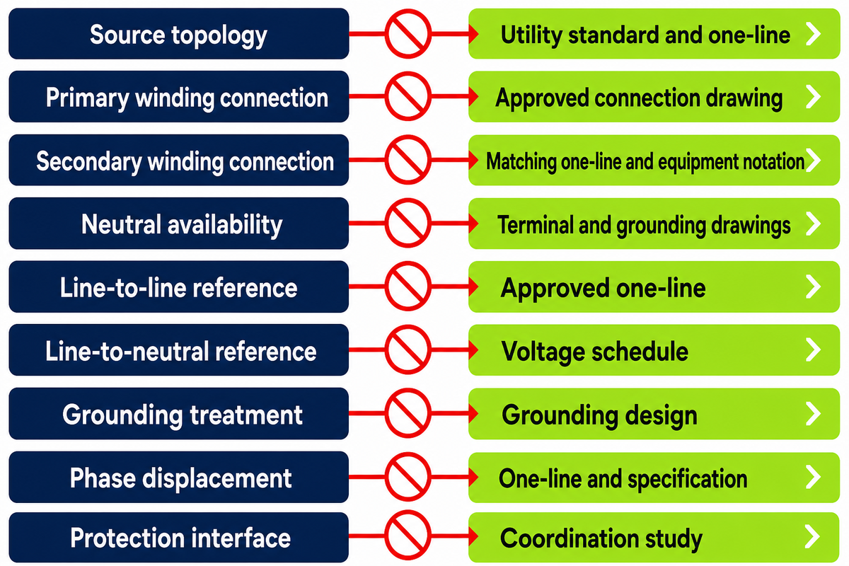
Pole, pad, vault, and substation labels describe installation interfaces; none selects a winding connection or neutral scheme. Record mounting separately as an independent project field, then confirm the primary and secondary connections, voltage references, grounding, and phase displacement from controlled documents.
| Type description | Phase field | Mounting field | Limitations / Not suitable for |
|---|---|---|---|
| Source topology | Incoming phase and topology | A location label does not identify the incoming circuit | Use the utility standard and one-line; keep open until labeled |
| Primary winding connection | Primary delta, wye, or approved alternative | An enclosure does not state the connection | Use the approved connection drawing; do not infer |
| Secondary winding connection | Secondary winding family | Mounting does not define the secondary arrangement | Require matching one-line and equipment notation |
| Neutral availability | Neutral status and use | A pad or pole label does not expose a neutral | Use terminal and grounding drawings; mark unknown |
| Line-to-line reference | Primary and secondary L-L values | Mounting carries no rated voltage reference | Use the approved one-line; label both sides |
| Line-to-neutral reference | Required L-N value | Installation style does not prove a usable neutral | Use the voltage schedule; state the reference explicitly |
| Grounding treatment | System grounding decision | Civil interface and grounding are separate decisions | Use the grounding design; route to the engineer |
| Phase displacement | Approved vector notation | Physical location does not select displacement | Use the one-line and specification; copy the approved value |
| Protection interface | Fault and protection relationship | Mounting does not establish fault behavior or settings | Use the coordination study; no web inference |
The matrix is a connection-scope control, not a Talite product matrix. Civil access, clearance, drainage, and environmental duty belong in a separate installation review and do not select a connection. The U.S. Department of Energy distribution-transformer webinar transcript separately lists mounting, phase, kVA, primary voltage, and secondary voltage as configuration attributes.
Evidence capsule
The 9-question matrix prevents a mounting label from deciding a winding connection, neutral scheme, voltage reference, grounding treatment, or phase displacement.
The 9-question matrix prevents a mounting label from deciding a winding connection, neutral scheme, voltage reference, grounding treatment, or phase displacement.
Connection Approval Inputs: Who Confirms Grounding and Protection Boundaries?
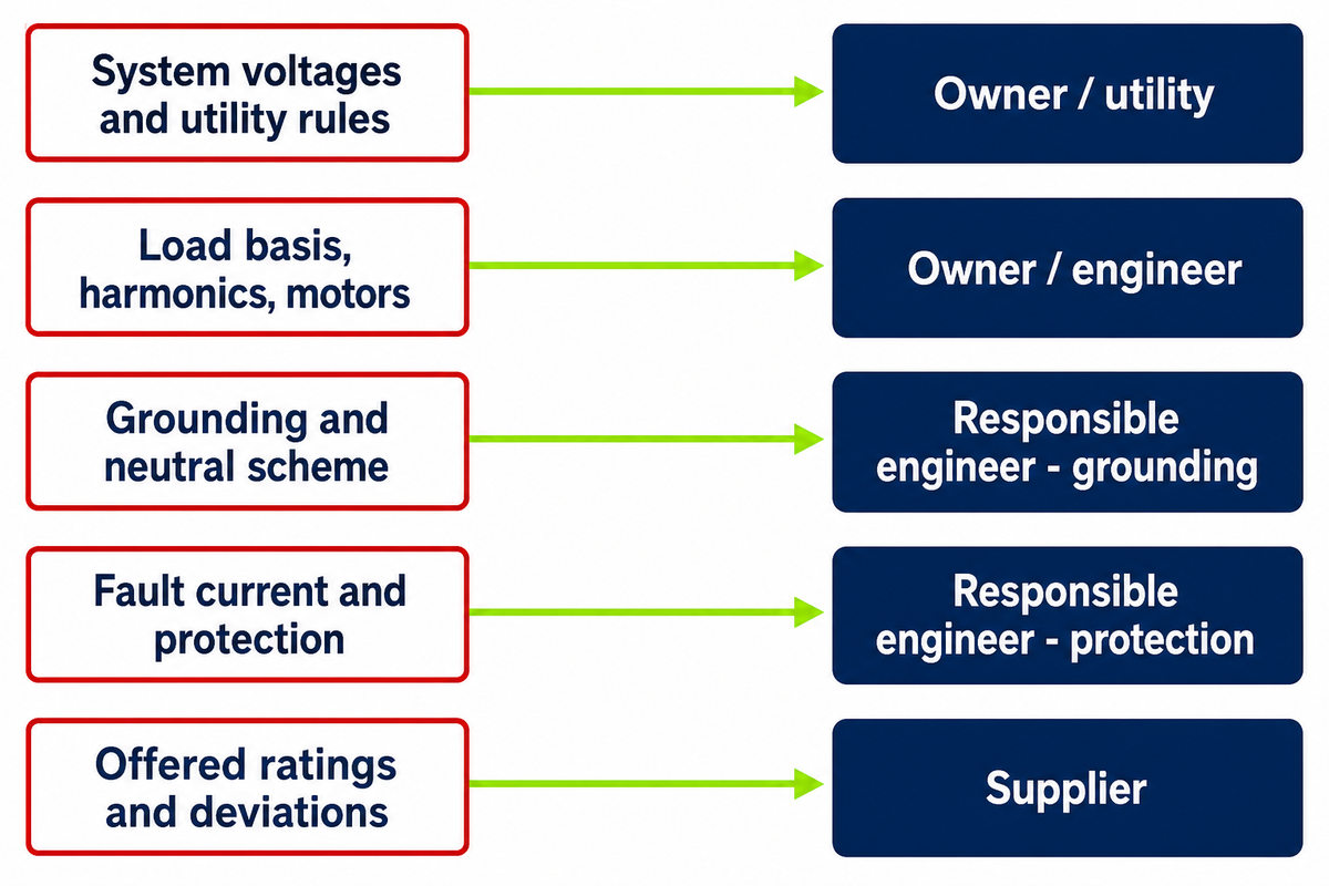
The owner or utility supplies governing system requirements, the responsible engineer confirms study-dependent decisions, and the transformer supplier confirms only the offered equipment data and documents. Grounding, fault current, impedance, inrush, power factor, and protective-device coordination must never be guessed from phase count or a sales description.
| Input | Primary confirmer | Required evidence |
|---|---|---|
| System voltages and utility rules | Owner / utility | Service standard and one-line |
| Load basis, harmonics, motors | Owner / engineer | Load schedule and study assumptions |
| Grounding and neutral scheme | Responsible engineer | Approved design |
| Fault current and protection | Responsible engineer | Coordination study |
| Offered ratings and deviations | Supplier | Data sheet and drawings |
Nonlinear or harmonic-producing loads can change the review, which is why IEEE C57.105 treats nonsinusoidal load application as a distinct engineering subject. Use the dedicated guides for transformer BIL requirements and distribution transformer protection inputs instead of compressing insulation and protection into one RFQ line.
Procurement objection resolved
The supplier may state offered impedance, ratings, tests, and deviations. The engineer and utility retain the decisions that depend on available fault current, magnetizing inrush, system grounding, and protective-device coordination.
The supplier may state offered impedance, ratings, tests, and deviations. The engineer and utility retain the decisions that depend on available fault current, magnetizing inrush, system grounding, and protective-device coordination.
Five Connection-Specification Traps Hidden by Generic Claims
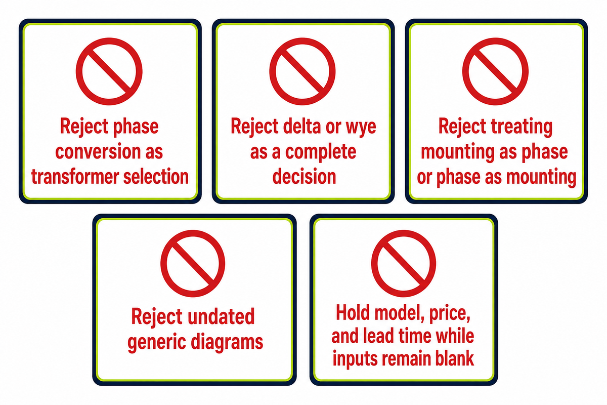
Generic promises of efficient power or balanced power do not define a reviewable three-phase connection. A connection brief identifies source topology, unit-or-bank architecture, rated voltage references, winding connections, neutral and grounding decisions, phase displacement, responsible parties, and controlled documents before model, price, or delivery questions are released.
Trap 1
Treating an unlabeled single-phase-to-three-phase conversion request as transformer selection rather than a separate system-design question.
Treating an unlabeled single-phase-to-three-phase conversion request as transformer selection rather than a separate system-design question.
Trap 2
Treating delta or wye as a complete grounding and protection decision.
Treating delta or wye as a complete grounding and protection decision.
Trap 3
Treating mounting as phase or phase as mounting.
Treating mounting as phase or phase as mounting.
Trap 4
Copying an undated generic diagram into a project specification.
Copying an undated generic diagram into a project specification.
Trap 5
Requesting a model, price, or lead time while controlling inputs remain blank.
Requesting a model, price, or lead time while controlling inputs remain blank.
When not to buy from a generic comparison
Do not release a purchase when the source topology, one-line revision, neutral and grounding treatment, load basis, utility acceptance, or protection responsibility is missing. There is also no universal “biggest disadvantage”: consequences vary between an integrated unit, complete bank, and approved special topology, as well as with outage, access, spare, and redundancy requirements. One public Division 26 specification illustrates why rated and connection fields belong in controlled project records rather than a generic comparison.
Do
- Hold blank fields open
- Route each decision to its owner
- Compare controlled revisions
Don’t
- Convert search demand into design advice
- Infer a rating from a familiar enclosure
- Accept marketing language as test evidence
Decision Framework: The Connection Brief Veto Queue
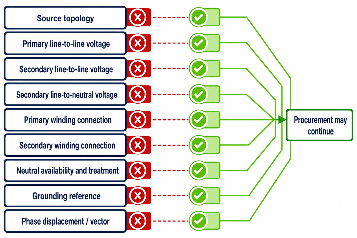
The Connection Brief Veto Queue blocks a connection decision whenever a required field is blank, conflicts across documents, or carries an unknown revision. Each row names the unresolved condition, the party that must clear it, the controlling evidence, and the point at which procurement may continue.
Connection Brief Veto Queue — resolve these connection fields before technical inquiry:
| Field | Owner | Controlling document | Release evidence | Limitations / Not suitable for |
|---|---|---|---|---|
| Source topology | Utility | Service standard and one-line | Accepted topology reference | Veto while the incoming system is unlabeled |
| Primary line-to-line voltage | Utility / engineer | One-line | L-L value labeled | Veto if the value or reference is missing |
| Secondary line-to-line voltage | Utility / engineer | Approved voltage schedule | One approved secondary L-L value; revisions agree | Veto when documents show different values |
| Secondary line-to-neutral voltage | Engineer / utility | One-line and load schedule | L-N value and need stated | Veto when the neutral reference is assumed |
| Primary winding connection | Engineer | One-line and specification | Approved notation matches | Veto when only a generic word or sketch exists |
| Secondary winding connection | Engineer / supplier | Approved drawing set | Terminal notation agrees | Veto when equipment and project drawings conflict |
| Neutral availability and treatment | Engineer / utility | Grounding and terminal drawings | Neutral status explicit | Veto when a common point is treated as approval |
| Grounding reference | Responsible engineer | Grounding design | Approved scheme identified | Veto when the method is inferred from a connection name |
| Phase displacement / vector | Engineer / utility | One-line and project specification | Approved value copied exactly | Veto when notation or revision is unknown |
Talite can review a supplied connection brief when buyers submit voltage and connection fields. The linked page does not by itself prove a requested rating, certification, connection, price, lead time, test result, or project outcome.
Key takeaway
A 9-row veto queue is ready only when each connection field has the required controlling evidence and clear-to-proceed evidence. A public Division 26 specification is one example of controlled project fields; the Connection Brief Veto Queue is Talite’s editorial tool, not the university’s method.
According to company-provided background, Talite Transformer Co., Ltd. has worked in the power-equipment sector for more than three decades, was originally established as Jiangsu Fangteng Industrial Co., Ltd., and integrates research, production, and sales in Nantong, Jiangsu. This is first-party company context, not independent proof of any product claim.
Bring a reviewable connection brief
Share the Connection Brief Veto Queue, approved drawings, utility requirements, and unresolved engineering inputs. Talite can review the offered equipment boundary without replacing the utility or responsible engineer.
Frequently Asked Questions
Which details are still missing after someone says “3 phase utility transformer”?
The phrase identifies a three-phase transformation duty but leaves the unit-or-bank architecture, primary and secondary voltage references, winding connections, neutral treatment, grounding, and phase displacement open. A 480 V or 277 V request remains incomplete until those fields are labeled. Frequency, such as a stated 50 Hz or 60 Hz requirement, also remains a separate controlled field.
The utility and project documents must identify the source topology, approved one-line, rated values, frequency, connection notation, neutral requirement, grounding scheme, and responsible approvers. A product label or familiar enclosure cannot supply those decisions. Record each value against the current document revision before a supplier compares an offered transformer or bank.
Is delta or wye the biggest connection tradeoff?
No single connection label determines the project tradeoff. Delta or wye wording still leaves neutral use, grounding, phase displacement, fault behavior, and protection requirements to the controlling documents and responsible engineer. Utility practice and load behavior decide which tradeoff matters for the actual circuit and duty.
Compare the source system, load behavior, approved vector notation, utility practice, grounding design, and coordination study rather than copying one advantage or disadvantage from a generic chart. The relevant tradeoff changes with the actual circuit and duty. If the source topology or neutral treatment is unresolved, the connection comparison remains open.
Does one unit versus a bank determine the winding connection?
No. An integrated three-phase unit or an approved bank describes architecture, while the one-line and connection drawings separately control the winding connections, voltage references, neutral, grounding, and phase displacement. Neither architecture authorizes a vector group or grounding method on its own.
The architecture split is not exhaustive because approved two-transformer and special arrangements exist. Matching only the kVA total or voltage labels does not establish connection equivalence, and mounting words such as pad or pole do not close the electrical fields. Treat the architecture and winding connection as separate rows in the controlled brief.
How do you wire a 3-phase transformer?
Do not use a generic article as field wiring instructions. Use only approved drawings and procedures under qualified control for the actual equipment and site.
Authorized, qualified personnel must control isolation, testing, terminations, switching, and energization under the approved one-line, manufacturer drawings, utility requirements, grounding design, protection study, conductor design, and site procedures. Drawing identity, revision, rated values, terminal notation, approval status, equipment condition, and the job safety plan must agree before field work. A buyer may record missing approvals and route discrepancies to the utility, responsible engineer, and supplier. This guide cannot verify conductor sizing, field terminations, switching steps, protection settings, arc-flash controls, test acceptance, or safe energization for a specific installation.
Can a transformer convert single-phase power to three-phase power?
A generic connection guide does not specify a single-phase-to-three-phase conversion solution. Treat phase conversion as a separate engineered-system question tied to the available source, required load behavior, utility rules, and responsible design authority.
A three-phase transformer or bank must be evaluated against the source topology defined by the system design. Do not select transformer architecture from this FAQ when the available supply and required load phase differ; first obtain an approved conversion concept and governing design inputs.
What standards apply to a three-phase transformer?
The controlling standards depend on transformer type, rating, insulation or cooling system, jurisdiction, utility requirements, and project specification. The project team must identify the governing editions and required acceptance evidence.
IEEE scope and U.S. DOE or eCFR context may be relevant, but a generic list cannot certify a specific product. The buyer, responsible engineer, utility, and supplier must identify applicable editions, deviations, required tests, and acceptance documents for the actual project.
Editorial and safety note
The three named frameworks are Talite editorial tools, not IEEE, DOE, EPRI, or utility methods. Standards and public project examples belong to their issuing organizations; they do not endorse Talite or prove a specific product.
The three named frameworks are Talite editorial tools, not IEEE, DOE, EPRI, or utility methods. Standards and public project examples belong to their issuing organizations; they do not endorse Talite or prove a specific product.
References & Sources
- IEEE C57.12.80-2024, Transformer Terminology IEEE Standards Association
- Transformers University of Central Florida / OpenStax — historical educational background, not current project evidence
- 10 CFR 431.192, Distribution Transformer Definitions Electronic Code of Federal Regulations
- Distribution Transformers U.S. Department of Energy
- Modeling the Open-Wye/Open-Delta Connection Electric Power Research Institute
- IEEE C57.105-2019, Nonsinusoidal Load Application Scope IEEE Standards Association
- Distribution Transformer Webinar Transcript U.S. Department of Energy
- Division 26 Electrical Specifications University of Maryland Facilities Management
Sources accessed August 31, 2026.
![Pad-Mounted Transformer: How It Works [2026 Guide]](https://toplit-transformer.com/wp-content/uploads/2026/08/pad-mounted-transformer-guide-featured-150x150.png)
![Single Phase Pad Mounted Transformer Guide [2026]](https://toplit-transformer.com/wp-content/uploads/2026/08/single-phase-pad-mounted-transformer-guide-featured-1-150x150.png)