Get in touch with Toplit Transformer Co., Ltd Company
How we use your enquiry information: Privacy Policy.

Engineering guide · Updated October 2026
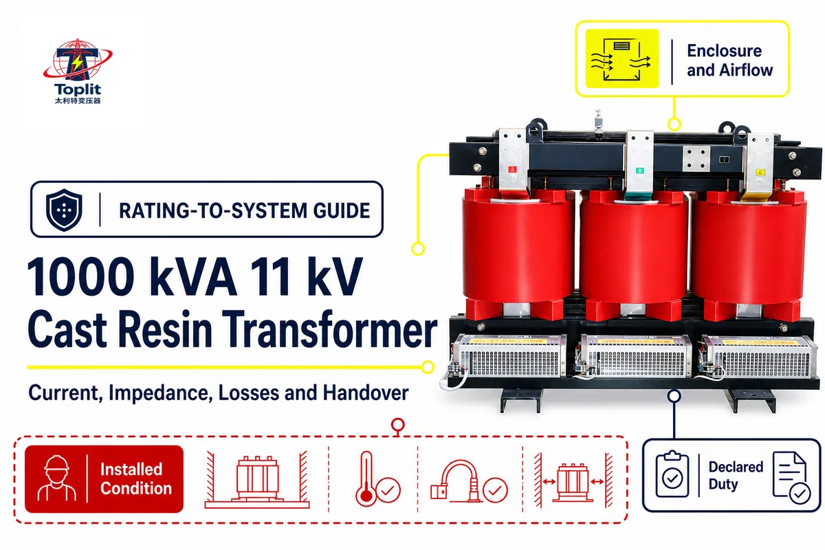
A 1000kva-11kv-cast-resin-transformer is a search label for a 1000 kVA cast-resin transformer with an 11 kV nominal high-voltage interface, not a complete specification; a project also needs the secondary system, exact-unit impedance and losses, site conditions, protection inputs, controlled drawings, test evidence, and a documented path to energization.
TL;DRA 1000 kVA, 11 kV label fixes apparent power and the nominal high-voltage interface. It does not fix the low-voltage current, vector group, neutral and grounding arrangement, impedance, losses, cooling, enclosure, harmonic capability, protection data, or acceptance evidence. Calculate nominal current only after naming the side and voltage, then pass the approved exact-unit data into the responsible system studies.
Search results for a 1000 kva 11 kv cast resin transformer are typically product listings. They’re useful when product comparisons need to be made based on configuration, dimensions, accessories, price, or delivery. This guide has a different job. It shows how to get from the four words in the rating to an engineering information set that’s reviewable.
Terminology note: listings often compress the same search into “1000kva,” “11kv,” “1000kva 11kv,” or “cast resin dry type.” In engineering documents, write the units with spaces and identify the exact side. An 11 kV dry type transformer used as a distribution transformer may serve power distribution inside an industrial substation, but that label does not define the secondary voltage, connection, neutral, grounding, or protection. Dry-type transformers can use different winding systems; an epoxy resin around a coil is one construction detail. A “3 phase” description still leaves voltage, connection, neutral, grounding, and protection open. UL or another destination-specific reference should be named only when the exact product and project require it. Search listings may call the category dry type distribution, cast resin dry type distribution, resin dry type distribution transformer, dry type cast resin transformer, power distribution transformer, dry transformer, or 11kv cast resin; these are search labels, not an approved configuration. A transformer manufacturer may also combine transformer 11kv, phase cast resin, 0.4kv, high and low voltage, air cooled, low loss, low noise, low partial discharge, electrical insulation, electrical equipment, power equipment, distribution system, power grid, electric power, power supply, and power solutions; each phrase still needs exact evidence. Model and rating labels such as SCB11, SCB13, S11, Dyn11, 50kVA, 100kVA, 750kVA, 1600 kVA, and 2000kVA, plus oil immersed transformer, are comparison vocabulary rather than specifications for this 1000 kVA unit. Commercial searches such as transformer price, price about transformer dry type, details and price about transformer, ISO9001, research and development, type and special test, and IEC standard belong to the solution-page or evidence review, not the rating calculation. Malformed strings such as transformer dry type transformer, resin cast dry, electronics power transmission, and transformer transformer are query noise and should never become technical claims. For commercial family navigation, use Toplit’s dry type transformer category.
To get a project-specific configuration or quote, go to Talite’s 1000 kva 11 kv cast resin transformer solution page. The focus here’s on interpretation and calculations, and the control of study and evidence inputs. That focus enables the Commercial Page to answer the buyer’s questions and this Page to answer the engineer’s questions that come before and after selection.
Headline rating → secondary-system definition → nominal-current check → impedance and loss data → site-condition review → protection and cable handoff → drawings and test evidence → authorized energization.
Use the map as a sequence, not a shopping list. The system diagram and load statement are used to determine which transformer fields are pertinent. From there, calculated currents are reconciled with the voltage ratio, and it’s verified that the impedance, losses, cooling state and environmental basis of design are aligned with the same revision. From there, the controlled values are passed to fault, protection, grounding, cables and room studies. Lastly, the approved studies are compared to nameplates, test records, drawings and the installed, as-built conditions. If a study changes, the impact of that change should be traced.
Revisions to the voltage ratio impact LV currents and downstream schedules; a change to impedance impacts fault duty; a change to enclosures or fans impacts room heat rejection. The map is complete only when those dependencies are visible and an authorized person has accepted the remaining exceptions.

Direct answer: 1000 kva indicates the rated apparent power under specified conditions. The 11 kv identifies the nominal line to line voltage of the high voltage interface. Together, they don’t wholly define a transformer specification for either winding or the connected system.
Apparent power is the combination of real and reactive power of a three-phase load, and is expressed in kVA. Transformer winding current and thermal duty aren’t defined by kW alone. The 11 kv indicates which side of the system the primary winding is intended to satisfy. The 11 kV figure tells you which side of the system the primary winding is intended to meet, but it doesn’t state the applicable highest voltage for equipment, insulation levels, frequency, tap range, or withstand duties. These fields need to be “frozen” independently.
The words cast resin describe an insulation construction, not a complete installation. They don’t specify the enclosure, cooling arrangement, environmental and climatic class, fire class, seismic class, accessories, compliance with the destination, or the exact acceptance plan. IEC 60076-11:2018 defines the standards framework for dry-type power transformers within its defined scope. Its official publication record identifies a 1000 kva restriction during the revision of fire behavior classes. That means the exact rating is relevant to class applicability, but it doesn’t let a reader determine a fire class from “1000 kVA” by itself.
| Known from the headline | Still must be confirmed |
|---|---|
| Rated apparent power: 1000 kVA | Load profile, overload expectation, harmonics, ambient, altitude, and cooling state |
| Nominal HV interface: 11 kV | LV voltage, frequency, highest voltage for equipment, insulation level, and taps |
| Dry-type cast-resin construction request | Vector group, neutral, grounding, impedance, losses, enclosure, accessories, classes, and evidence |
The first review task is subtraction: remove all assumptions that the headline doesn’t actually support. What’s left is the project’s open-input list.

Direct answer: The nominal line current for a balanced three-phase transformer is given by I = S ÷ (√3 × V). To close the open-input list from the previous section, use the line-to-line voltage of the side being calculated and keep the units consistent.
Using kVA and kV converts the answer to amperes. On the 11 kv side:
IHV = 1000 ÷ (√3 × 11) ≈ 52.5 A
The low-voltage current can’t be calculated until the actual secondary voltage is known. At 415 V, expressed as 0.415 kV:
ILV,415 = 1000 ÷ (√3 × 0.415) ≈ 1,391 A
At 400 V:
ILV,400 = 1000 ÷ (√3 × 0.400) ≈ 1,443 A
The 15 V variation between those two LV systems impacts nominal current by approximately 52 A. This variation is substantial enough to impact the discussion of busbars, cables, CTs, switchboards, and protection. It’s for this reason that safely reproducing “the current of a 1000 kva transformer” without indicating the side and voltage is unacceptable.
This arithmetic is a plausibility check. It isn’t a calculation to determine cable ampacity, breaker selection, CT ratio, relay pickup, fuse size, overload permission, or validation that a 1000 kva load is acceptable under all conditions. To verify other voltages without repeating the calculation, use Toplit’s existing three-phase transformer current calculator.

Direct Answer: the secondary voltage determines the LV current for a given kVA. The vector group describes winding connections and phase difference and can also show if a neutral point is available. The actual grounding method determines how that neutral is used and how earth-fault current flows.
The phrase “1000 kVA, 11 kV” still leaves the receiving system undefined. Nominal currents are different for 400V and 415V secondaries. Delta- and wye-connected secondaries are different neutral interfaces. Phase difference matters for transformers that operate in parallel or for protection and metering comparison across windings.
| Interface category | What it changes | Where to confirm it |
|---|---|---|
| Secondary voltage | LV nominal current and downstream utilization voltage | Approved data sheet, single-line diagram, and nameplate |
| Frequency | Design basis, losses, flux, and destination compatibility | Project basis and approved data |
| Vector group | Connections, phase displacement, neutral availability, and parallel-operation screening | Connection diagram, approved drawing, and nameplate |
| Grounding method | Earth-fault path, fault magnitude, protection behavior, and touch-voltage study inputs | Grounding study, protection design, and single-line diagram |
| Tap arrangement | Available ratio adjustment and operating procedure | Approved data, nameplate, and manual |
| Insulation basis | Highest voltage for equipment, withstand duties, clearances, and test scope | Insulation-coordination record and approved data |
| Impedance and tolerance | Fault model, voltage drop, coordination, and parallel-operation screening | Approved design and agreed exact-unit test record |
| Cooling and enclosure | Available rating state, heat rejection, contamination control, and room interfaces | General arrangement, control drawing, and exact manual |
| Monitoring and protection | Sensors, alarms, trips, CT interfaces, and study inputs | Accessory list, wiring diagram, and protection files |
Neutral availability and grounding design are not the same. IEC 60076-25:2023, for example, covers neutral-grounding resistors used to limit earth-fault current and recognizes combinations with other equipment where a neutral point is unavailable. That does not mean every 1000 kVA project needs such a resistor. It means the handoff must explicitly state the grounding design, earth-fault path, and responsible study rather than relying on a vector-group code.

Direct answer: Short-circuit impedance is an exact-design and test quantity that influences fault current, voltage drop, protection coordination, and parallel operation. Short circuit impedance is one required input parameter, not a complete available fault current answer or a substitute for the source-network model.
For a first-order illustration, assume an infinitely strong source and ignore every contribution except the transformer. If a hypothetical 1000 kVA transformer had 6% impedance, its transformer-limited short-circuit apparent power would be approximately 1000 kVA ÷ 0.06, or 16.7 MVA. At a hypothetical 415 V secondary, that corresponds to about 23.2 kA. The example explains direction and scale only. The 6% value isn’t a Toplit specification, and the result isn’t a project fault level.
Various factors must be considered in a complete study of a transformer, such as the source impedance, the utility fault level, the impedance of the conductors and cables, the configuration of the system, the tolerances of the system impedance, the contribution of motors and generators, earthing, the modes of operation and the calculation method. IEC 60909-0:2026 is a method for calculating short circuit currents in a three-phase AC system. For this reason, an arbitrary short-circuit impedance should never be pasted into a report.
| Question | Needed evidence | Decision owner |
|---|---|---|
| What impedance enters the model? | Approved exact-design value, tolerance, tap/reference conditions, and exact-unit test record where required | Transformer supplier and study engineer |
| What fault current is available? | Validated source, network, conductor, machine, and operating-state model | Responsible power-system engineer |
| Can the transformer withstand the duty? | Specified thermal and dynamic short-circuit-withstand evidence | Designer, supplier, and acceptance authority |
| Are protection and equipment duties coordinated? | Equipment ratings, conductor limits, CT data, relay models, clearing times, and settings study | Protection and system engineers |
IEC 60076-5 states that the overcurrent calculation and the determination that a transformer will withstand the thermal and dynamic effects of an external short circuit must be kept as two separate lines of evidence. Keeping these two lines of evidence separate avoids a common error, that is, a calculated fault level may be correct, and yet evidence that the equipment will withstand the fault may be missing.

Direct answer: No-load loss is predominantly related to an energized core at the stated voltage and frequency. Load loss is predominantly related to current and its reference conditions. Useful comparisons therefore need both stated values and the expected operating profile.
A lightly loaded transformer can accumulate core-related energy loss during every energized hour. A heavily loaded unit gives more importance to load loss, which is related to current and must be compared on a consistent reference basis such as the one discussed in Department of Energy transformer guidance. That’s why one headline efficiency percentage can reflect a multitude of operating questions. The same design may appear very different when utilized in a 24/7 light industrial load, variable process load, or in a data center duty with significant harmonics.
The Load Profile Evidence Loop states that guaranteed no-load and load loss values must be requested, conditions of tests and references must be confirmed, and the values mapped against anticipated energized hours and loading. If the duty changes, the comparison must also change. A lifecycle cost claim also requires the electrical price of energy, financial assumptions, expected operating years, limits of maintenance, and validated loss data. This guide doesn’t create those values.
Keep similar comparisons when proposals use different reference conditions. Record the declared value, the temperature or test basis, cooling state, tolerance or guarantee wording, and the document revision. If one proposal gives a guarantee, and another gives a figure typical of a catalog, then the figures don’t have the same contractual weight. The buyer’s load duration profile should remain an input file, not an internal assumption in a spreadsheet. This way, a change in operating hours or loading can be recalculated without altering transformer evidence.

Direct answer: Harmonics, ambient temperature, altitude, enclosure, ventilation, contamination, condensation, load cycle, and cooling state can make “below 1000 kVA” an incomplete suitability test; each input connects the rating review to the actual installation, the preceding current calculation, and the responsible thermal assessment.
Rated capability is dependent on declared conditions within the application scope described by IEC 60076-11. Higher altitudes affect cooling and dielectric considerations. Enclosures that restrict airflow or recirculate hot air reduce heat rejection. Dust, moisture, salt, chemicals, and condensation can alter the environmental protection needed. Forced-air cooling can create multiple rating states, and the operating team must know what state is available to them when making a load decision.
Nonsinusoidal current should be addressed separately in the input schedule. Drives, rectifiers, UPS systems, chargers, and other power-electronic loads can increase winding and stray losses even when the ordinary kVA total looks acceptable. The correct answer won’t be a generic derating percentage. Give the load spectrum or best available waveform, and have an exact-design evaluation done using the applicable methods.
| Condition | Input still needed | Evidence or decision |
|---|---|---|
| Harmonic load | Current spectrum, RMS loading, duty cycle, and future load | Thermal/capability evaluation for the exact design |
| Ambient and altitude | Normal, average, maximum, minimum, and installation elevation | Approved thermal and dielectric basis |
| Enclosure and airflow | Room heat rejection, openings, recirculation risk, and obstructions | Room calculation, approved drawing, and exact manual |
| Contamination and condensation | Dust, moisture, salt, chemicals, storage, and de-energized periods | Protection, materials, heaters, cleaning, and inspection plan |
| Cooling state | Natural/forced state, fan supply, controls, alarms, and failure response | Control diagram and operating authorization |
General construction and maintenance questions belong in Toplit’s broader cast resin transformer construction and lifecycle guide. The present article stays with the 1000 kVA/11 kV rating-to-system interface.

Direct Answer: Provide the exact transformer data, source and network data, load and grounding data, CT and sensor data, and controlled revision ID to the interested studies on protection, switchgear, and cables. Those site conditions identified in the preceding review mean nominal current is not universal.
Rated voltages and currents · frequency · vector group · neutral and grounding method · impedance and tolerance · tap data · losses and test basis · available inrush/energization information · CT characteristics · temperature devices · source fault data · downstream topology · conductor installation · equipment ratings · clearing assumptions · revision and approval status.
Only one aspect of energization is captured by continuous rated current. Other considerations include magnetizing inrush, CT saturation, relay restraint, and fault response. These must be synchronized with limits imposed by the equipment and the line. Re-energization conditions may be critical after a trip. IEEE C37.91-2021 discusses these topics for transformer protection; its main stated scope is transformers above 5 MVA. It mentions that users may be able to apply the ideas in the document to protect transformers less than 5 MVA. If the responsible engineer deems it applicable, it may be used for a 1 MVA project as a checklist.
A compact handoff line might identify 1000 kVA, 11 kV, the approved 0.4 kV or 0.415 kV secondary, 50 Hz or 60 Hz, the calculated 52.5 A HV current, the applicable 1,443 A or 1,391 A LV current, impedance in %, losses in W or kW, ambient limits in °C, and altitude in m. Only the approved variations are in the final line; the paired values are shown to explain why unmarked numbers are not adequate.
For applicable US circuits above 600 V, OSHA 1910.304 requires protective devices to detect and interrupt applicable overcurrent values. It ties together protective-device operating time, available short-circuit current, and conductor coordination. This is a jurisdictional example, not a global settings table. The broader principle is portable: name who owns the study and give that person the inputs and revisions needed to make a defensible decision.
The handoff should end with an output list: cable schedule, switchgear duty check, CT and relay model, coordination study, approved settings, grounding-study result, alarm/trip matrix, and revision-controlled single-line diagram. Values for these parameters aren’t provided in this documentation.

Direct answer: The requirement register, approved data sheet, drawings, nameplate, exact-unit test record, short-circuit-withstand evidence, receiving record, installation exceptions, protection-study revision, and energization authorization should describe one consistent transformer and one controlled system state before any party authorizes energization or closes an exception.
A test report is only valuable when its identity and acceptance basis are defined. A family report may support a type-test claim but can’t replace an exact-unit routine-test record. Within its scope, a standards reference such as IEC 60076-1 explains the method or requirement set; it is not evidence that a particular serial-numbered unit passed. A nameplate serves as proof of what’s marked on the unit, but it doesn’t prove that surrounding cables, settings and airflow are as designed.
The most valuable control is an exception register, shared by procurement, supplier, contractors, consultants, the commissioning team and the Owner. Each entry should provide requirement, condition, impact, owner, disposition, due date, recheck evidence and closure authority. This keeps an outdated drawing, a damaged component, a temporary fan supply, an unverified alarm, or an unresolved moisture event from being lost between teams.
Place revision IDs by any input that could impact a study or acceptance decision. Minimally capture the approved data-sheet revision, single-line revision, connection and general arrangement drawing revisions, protection-study issue, cable schedule issue, test-plan revision, and serial number or manufacturing identity of the delivered unit. A file name alone is weak evidence because teams can overwrite it, or circulate an exported PDF after the source drawing changes.
Compare the revision table rather than ask each discipline whether its work is “complete,” before energization. The protection study may be complete against an earlier impedance. The cable schedule may be complete against 400 V while the released secondary is 415 V. The test report may be authentic but tied to a different unit. Drawings may be approved while a site change has moved an obstruction into the cooling path. A short, signed reconciliation of these identities is more valuable than another generic checklist.
Establish a record of dependencies. Changing impedance can affect fault duty and protection. Changing the vector group or grounding method can affect earth-fault behavior and parallel-operation screening. Changing losses or cooling can affect room heat rejection. This dependency record turns document control into an engineering control.

Direct answer: move to the solution page when the project needs a final voltage ratio, vector group, impedance, loss assurance, enclosure, cooling arrangement, accessory, drawing, test, dimensions, price, lead time, or quotation before cable sizing, equipment duty, or relay settings are approved.
Handoffs should be done before quotes are requested. The HV and LV ratings, frequency, expected duty and load profile, harmonics, vector group and grounding requirements, fault study requirements, ambient and altitude, enclosure and room condition, cooling state, accessory, monitoring, and destination should be provided. The applicable power-transformer standards, documents, tests, and schedule should also be provided. This gives supplier and the buyer the opportunity to evaluate an accurately scoped and defined project, instead of making trade offs based on assumptions.
Talite Transformer Co., Ltd. describes its company and production context on the About Us page. For the selected transformer, request evidence tied to the exact proposal and delivered design. Company history and general capabilities shouldn’t be provided in lieu of project documentation.
Discuss a documented 1000 kVA project
For balanced three-phase nominal current, use I = S ÷ (√3 × V). At 11 kV, 1000 kVA is about 52.5 A. At 415 V it’s about 1,391 A, and at 400 V about 1,443 A. These are rated-current checks. Cable, busbar, breaker, fuse, CT, and relay decisions still require the actual duty, installation, temperature, harmonics, fault study, protection study, and applicable rules. State which winding the number belongs to and which cooling condition applies. Then compare the arithmetic with the approved nameplate and project study; don’t treat the calculated current as permission to load equipment or as a substitute for protective-device coordination.
The search phrase “1000 kVA transformer impedance” does not map to one safe universal value. Impedance is tied to the exact design, reference conditions, taps, and tolerances. Obtain the approved value and the agreed exact-unit test evidence, then use it with source impedance, cables, machines, topology, and operating state in the responsible engineer’s study.
It normally identifies the nominal line-to-line voltage of the high-voltage winding or system interface. It doesn’t by itself state the applicable highest voltage for equipment, insulation level, secondary voltage, vector group, tap range, frequency, impedance, or destination compliance. Confirm those fields in the approved data, drawings, and nameplate. Keep rated voltage separate from the insulation-coordination and test basis.
No. kVA is apparent power and kW is active power. Their relationship depends on the load power factor, and system losses also matter. A 1000 kVA rating therefore doesn’t promise 1000 kW for every load. Use the expected power factor and operating profile in the load study.
Only when the exact design, declared service conditions, cooling state, load waveform, and project requirements support that duty. Ambient temperature, altitude, enclosure, airflow, harmonics, fans, load cycle, and applicable rules can change the evaluation. Confirm the manufacturer’s rated conditions and the project engineer’s load study.
Yes. Cast-resin construction removes insulating-liquid management, but it doesn’t remove inspection of cooling paths, contamination, connections, supports, grounding, sensors, fans, alarms, moisture, corrosion, physical condition, and document changes. The exact manual and site safety program determine the work and intervals.
Searches for “1000 kVA dry type transformer dimensions” still require an exact design because dimensions are not determined by kVA alone. Voltage ratio, insulation level, impedance, loss design, enclosure, cooling, destination rules, cable interfaces, and accessories can change the footprint and mass. Use the approved general-arrangement drawing for the selected project configuration.
Cost depends on the electrical schedule, impedance, loss requirements, enclosure, cooling, accessories, tests, documents, destination, logistics, and delivery schedule. A static blog price would quickly become inaccurate. Send the complete project input set through the existing solution Page for a scope-matched quotation.
Toplit publishes transformer field guides from project routing, factory loss-data discipline, and specification review experience. We help engineering and procurement teams compare transformer types, voltage classes, installation constraints, and quotation evidence before they commit to a build.