Get in touch with Talite Transformer Co., Ltd Company

Updated September 2026
A pad mounted transformer diagram is a broad label for visual records that may show equipment zones, electrical relationships, connection identifiers, dimensions, or nameplate data. No single diagram answers every project question because the system relationships, civil interface, and unit-specific data may appear in separate controlled records.
The reliable reading order is document first, device second: identify the title block and revision, follow the legend, then compare the drawing with the approved system record, the manufacturer submittal, and the equipment nameplate. For broader system, safety, and lifecycle context, use Talite’s pad-mounted transformer system guide; generic online images cannot authorize enclosure access, field wiring, testing, switching, or energization.
- Identify the document — read the title, owner, drawing number, revision, and stated purpose.
- Locate the zones — separate the tank, primary side, secondary side, and civil interface.
- Trace each mark — connect a symbol to its legend, function, and equipment identifier.
- Reconcile the records — compare phase, voltage, rating, revision, and nameplate identity.
- Escalate the unknowns — send unresolved fields to the manufacturer, utility, engineer, or authority responsible for approval.
What a Pad Mounted Transformer Diagram Actually Shows
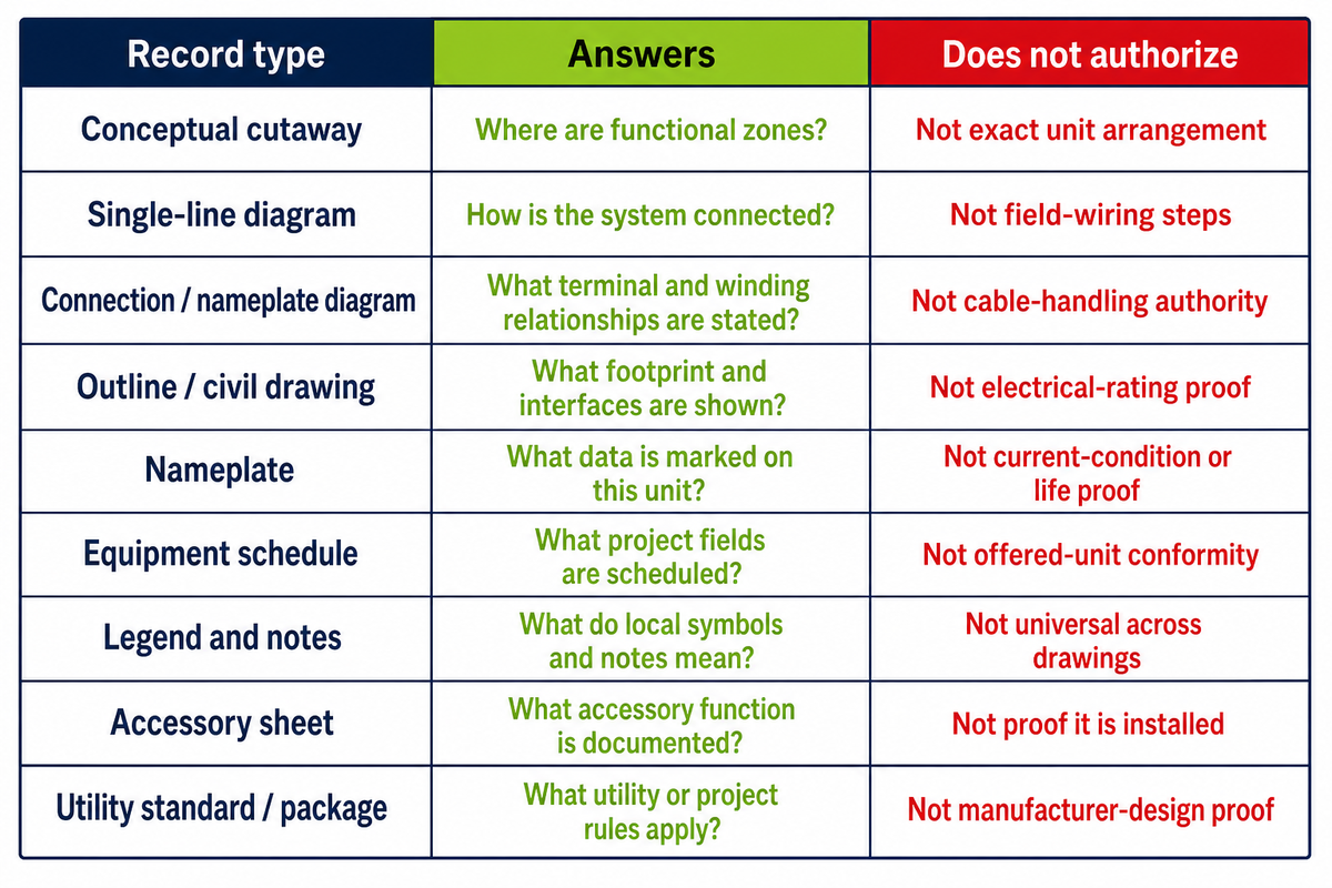
Transformer diagrams become useful only after their document type is known. Conceptual cutaways answer “where might the main zones be,” while one-lines answer “how are system elements related”; neither record proves the dimensions, terminal arrangement, or approval status of a particular unit.
| Record type | Primary question | What it does not authorize |
|---|---|---|
| Conceptual cutaway | Which zones and component families may be present? | Exact placement or unit identity |
| Single-line diagram | How does the transformer relate to the electrical system? | Field connection sequence |
| Connection or nameplate diagram | How are the unit’s identified windings and terminals represented? | Cable preparation or switching |
| Outline or civil drawing | What footprint, base, and conduit interfaces must align? | Universal pad or clearance |
| Nameplate | Which ratings and identity fields belong to the equipment? | Condition, remaining life, or project acceptance |
| Equipment schedule | What design basis is assigned to the equipment tag? | Final manufacturer dimensions or terminal positions |
| Drawing legend and notes | How does this drawing define its symbols and exceptions? | Meaning for a different drawing or revision |
| Accessory sheet | Which optional or specified devices belong to the offered design? | Presence on an unverified unit |
| Utility standard or package | Which owner-specific interfaces and review rules apply? | Acceptance by another utility or authority |
The IEEE C57.12.28-2023 enclosure-integrity scope, for example, concerns above-grade enclosures containing apparatus energized above 600 V that may be exposed to the public. Its scope does not turn it into a connection or civil drawing.
A drawing label therefore sets the first boundary: answer the question named by the record, and refuse to infer the questions it was never made to answer.
5-Step Diagram Reading Map: Document Before Device
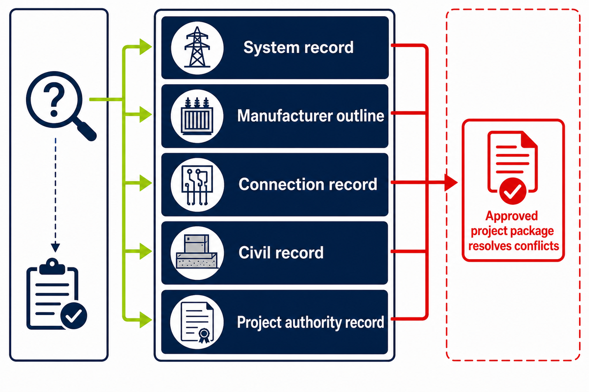
The Document Stack Before Device method sorts records by question before anyone studies the transformer itself. It is a Talite editorial taxonomy, not an IEEE term or a fixed order of contractual precedence; the approved project package must define which record controls when two documents disagree.
The five-layer document stack
- System record: approved one-line, equipment schedule, and design basis.
- Manufacturer outline: general arrangement, mass, footprint, and interface locations for the offered unit.
- Connection record: winding, terminal, polarity, tap, and nameplate relationships stated for that design.
- Civil record: pad, anchoring, conduit, access, drainage, and site interface.
- Project authority record: utility requirements, approved submittals, specifications, and responses to review comments.
The USDA RUS underground-distribution drawing bulletin separates equipment pads, grounding assemblies, and a single-phase radial-feed transformer unit. The same bulletin says its guidance gains force only when authorized or incorporated into a contract, which is precisely why a detailed-looking public drawing is not automatically the controlling project sheet.
The USACE ER 1110-345-700 design-record framework likewise treats power plans, grounding plans, specifications, staged submittals, revisions, and signatures as distinct controlled records.
“The electrical and mechanical requirements of any accessory devices that may be supplied with the transformer are not covered in this standard.”
That exclusion matters when a drawing shows a switch, fuse, meter, arrester, or sensor. The applicable manufacturer and project records must establish what the accessory is and how it belongs to the offered unit.
Enclosure Layout and Main Components
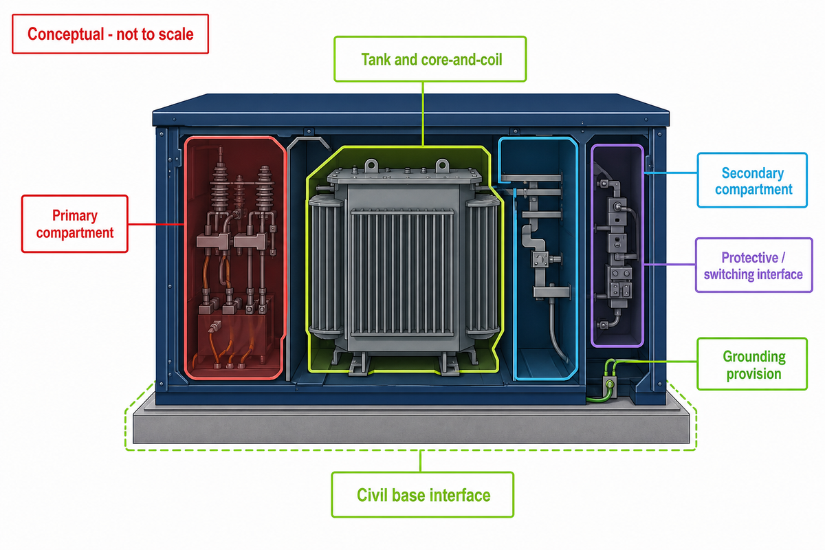
Conceptual enclosure layouts can map functions without claiming a universal arrangement. Start by distinguishing the tank and core-and-coil assembly from the cable compartments, then use the unit’s legend and outline drawing to identify bushings, terminals, protective interfaces, switching interfaces, grounding provisions, and any stated indicators.
Conceptual visual rule
Generated cutaways must be labeled “conceptual; not to scale.” They may show functional zones, but they must not invent terminal counts, ratings, cable positions, or accessory details for a real product.
| Label family | Function to understand | Verify in |
|---|---|---|
| Tank, core, and windings | Magnetic and insulated transformation assembly | Manufacturer outline and unit data |
| Primary bushings or connectors | Interface to the stated primary system | Connection diagram and utility package |
| Secondary terminals | Output-side terminal identity | Nameplate and connection record |
| Fuse or switching mark | Protective or isolating function stated for the design | Legend, accessory sheet, and approved submittal |
| Grounding provision | Identified bonding or grounding point | Equipment and project grounding records |
The City of Healdsburg transformer specification, section 13.2 gives a useful named example: its final package calls for overall dimensions, footprint, clearances, weight, device locations, parts list, nameplate, and instructions before manufacture or shipment. Those fields show how much a real submittal contains beyond a web illustration; they are not universal requirements outside that specification.
Symbol-to-Function Trace
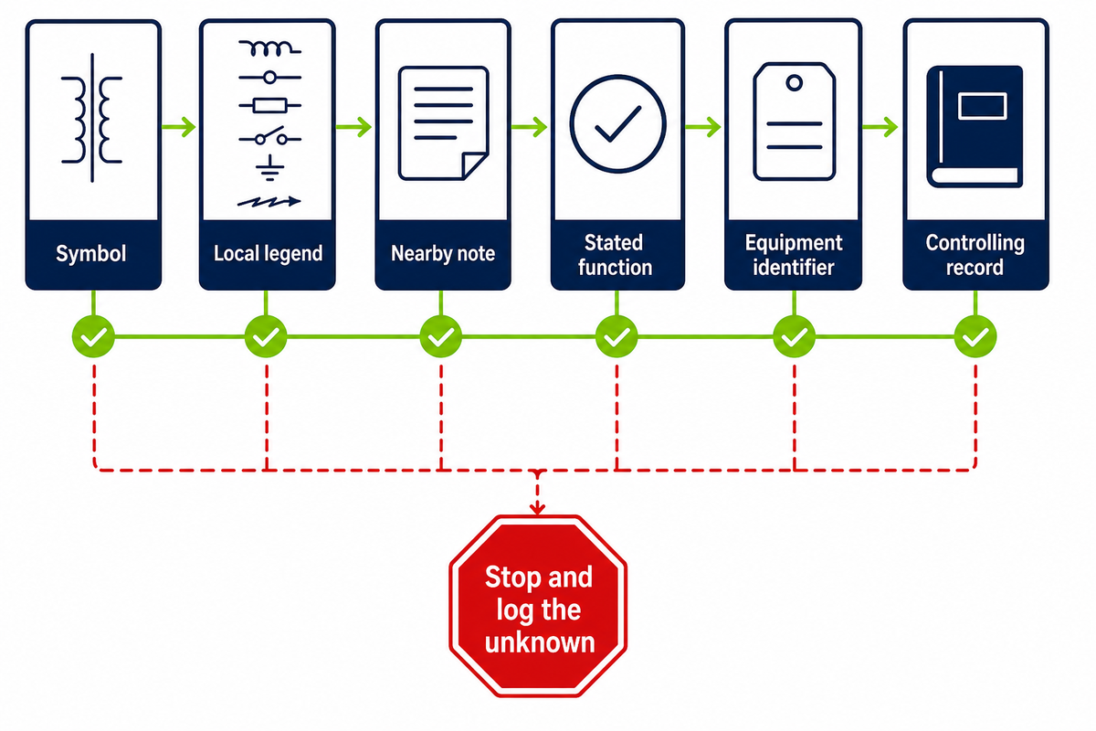
The Symbol-to-Function Trace prevents a familiar mark from becoming an unsupported assumption. Move from symbol to legend, from legend to stated function, from function to equipment identifier, and from that identifier to the controlling record; stop when any link in that chain is absent.
- Find the local legend. Do not begin with a generic symbol chart.
- Read the nearby note. A cross-reference can narrow the symbol’s meaning.
- Name the function. Separate winding, terminal, fuse, switch, grounding, and arrester roles.
- Match the identifier. Compare H/X labels, phase marks, or device tags with the equipment schedule and nameplate.
- Record the unresolved item. Ask the drawing owner instead of filling a gap from memory.
H1, H2, H3 and X1, X2, X3 are common terminal-style labels, but the presence and meaning of a particular group must be read in the context of the unit’s diagram. A winding symbol shows an electrical relationship; it does not reveal conductor material, insulation system, physical lead route, or a safe work method.
Do
- Read the drawing title and revision first.
- Use the legend attached to that drawing.
- Match labels against the equipment schedule and nameplate.
- Log an unresolved cross-reference.
Don’t
- Infer a device from enclosure appearance.
- Copy a symbol meaning from another manufacturer.
- Treat a connection plate as a work instruction.
- Assume a visible accessory falls inside a phase-family standard.
The result is a defensible reading trail rather than a confident guess. It also gives procurement staff a precise question to send back: “Which record defines tag F1 on drawing revision C?” is answerable; “Does this generic symbol mean the same thing everywhere?” is not.
Search labels are not document titles. A page returned for pad mount transformer wiring diagram may be only a connection plate, while a pad mounted transformer grounding diagram may show a project grounding detail. Likewise, a 3 phase pad-mounted transformer diagram, a pad-mounted transformer diagram PDF, or a pad mounted transformer installation page still requires title, revision, owner, and scope checks.
How to Treat Search-Term Labels
The components of a pad-mounted transformer cannot be confirmed from a search phrase alone. Use each label below as a field to verify against the drawing set, not as proof that the feature exists on the unit.
- Naming varies: padmount transformer, padmount, and the compressed phrase type transformer may point to different records; a general definition may say a pad-mounted transformer is a ground-mounted electric power distribution transformer, but the same result cannot prove that every transformer is a ground-mounted electric unit.
- Configuration labels such as single-phase pad-mounted distribution transformers, three-phase transformer, pole mounted, substation, and switchgear must remain separate because mounting form, phase family, and system role are different fields.
- System language such as electric power distribution, electrical distribution, delivery of electricity, single-phase power, lower secondary voltage, Wye, and short-circuit describes relationships that still need the approved one-line and rating records.
- Interface terms such as HV, medium-voltage, separable insulated interfaces, separable insulated high-voltage connectors, load break elbows, arresters, a current limiting fuse, and other electrical components require an accessory sheet or unit-specific connection record.
- Material wording such as mineral oil, FR3, dielectric, aluminum or copper, copper or aluminum, or “the core is made from” must come from a unit-specific document rather than a conceptual cutaway.
- Performance wording about how a transformer operates, transformer design, rated capacity, transformer failure, fault conditions, how transformers are designed, or whether equipment is designed in accordance with an IEEE or IEC standard needs a cited test, rating, or conformity record.
- Work-related phrases such as proper installation, installation and maintenance, operation and maintenance, safety and maintenance, safe and efficient, or efficient and safe operation fall outside a generic diagram; if a page says a step determines whether work is done properly, the governing procedure and qualified party still need to be named.
- Commercial phrases such as “transformers are available” or “transformers are used in industrial and residential settings” do not establish the offered configuration, project approval, or delivery status.
Phase, Feed, and High-Voltage Interface Labels
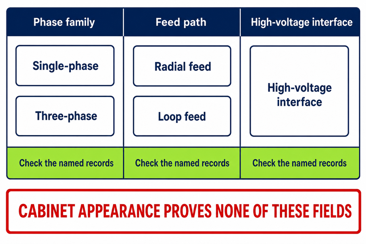
Single-phase versus three-phase and radial versus loop feed must be checked as separate record fields. The phase family changes winding and terminal relationships, while the feed label describes the primary path; enclosure appearance alone does not establish either field or the high-voltage interface type.
| Public scope | Bounded figures | Reading consequence |
|---|---|---|
| IEEE C57.12.38-2025 | Single phase, 60 Hz, 250 kVA or smaller, high voltage at or below 34,500 GrdY/19,920 V, low voltage at or below 480/240 V | Use for its stated single-phase family; do not infer accessory details. |
| IEEE C57.12.34-2022 | Three phase, 60 Hz, 10 MVA or smaller, high-voltage system at or below 34.5 kV, low-voltage system at or below 15 kV | Use for its stated three-phase family; do not apply it as the single-phase baseline. |
For a scope check, copy the units as written: the single-phase row states 60 Hz, no more than 250 kVA, up to 34,500 GrdY/19,920 V on the high side, and no more than 480/240 V on the low side. The three-phase row states 60 Hz, no more than 10 MVA, up to 34.5 kV on the high-voltage system, and up to 15 kV on the low-voltage system; these are standard-scope ceilings, not project selections.
Sources: IEEE C57.12.38-2025 and IEEE C57.12.34-2022. These values describe the public standard scopes, not Talite product ratings and not evidence that a particular transformer conforms.
Radial feed and loop feed
Radial-feed records represent one primary source path to the transformer. Loop-feed records represent a through path with an incoming and continuing side in the stated system design. Both IEEE pages above cover connector, bushing, and terminal arrangements for radial or loop-feed systems within their own phase-family scopes.
Live-front and dead-front descriptions
These terms concern the form of the high-voltage interface, not the number of phases or the feed path. Project reviewers should record the exact wording in the manufacturer and utility package rather than infer it from cabinet proportions. This article gives no cable-handling or switching sequence.
The two standards also show why revision control matters. IEEE’s history for C57.12.38 records a corrigendum to the 2014 edition after two bushing-height dimensions appeared in one figure; an authentic old sheet can still contain a corrected error.
The Revision Triangle
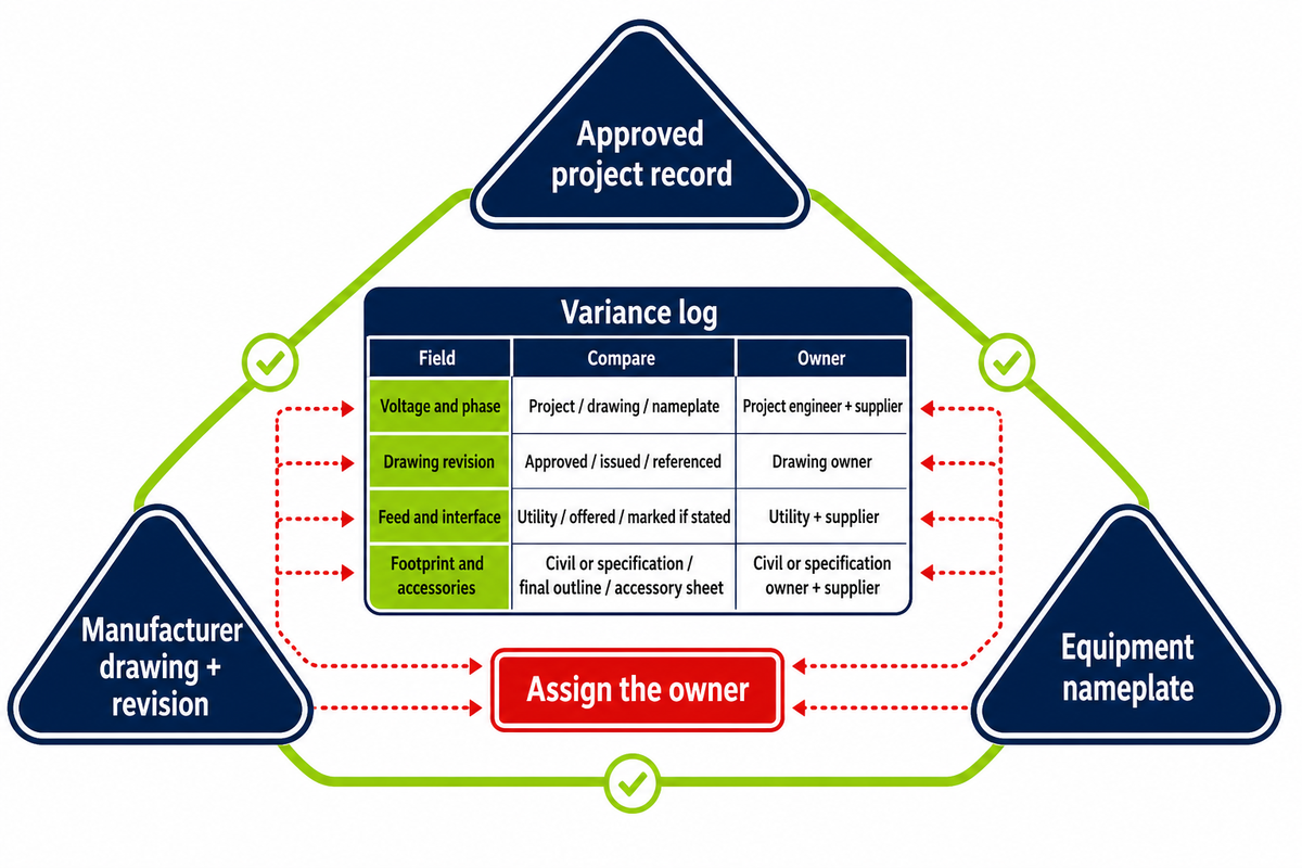
The Revision Triangle compares three identities before a diagram is used for procurement or project review: the approved project record, the manufacturer drawing and revision, and the equipment nameplate. Matching kVA values alone are too weak because voltage, phase, frequency, connection, serial identity, and cited standard may still differ.
1. Project record
Approved one-line, equipment schedule, design basis, and utility package.
2. Manufacturer record
Drawing number, revision, outline, connection sheet, and submittal identity.
3. Equipment record
Manufacturer or serial identity, rating fields, nameplate diagram reference, and stated standard.
Build a variance log with one row per mismatch. Record the field, the value found in each of the three records, the drawing owner, the party responsible for clarification, and the disposition. Do not erase an old value from the audit trail merely because a newer drawing looks plausible.
| Field | Project record | Manufacturer record | Nameplate | Owner to resolve |
|---|---|---|---|---|
| Voltage and phase | Record stated value | Record stated value | Record stated value | Project engineer and supplier |
| Drawing revision | Approved reference | Issued revision | Diagram reference, if stated | Drawing owner |
| Rating and impedance | Scheduled basis | Offered value | Marked value | Engineer and manufacturer |
| Frequency | System basis | Design value | Marked value | Project engineer |
| Feed arrangement | Radial or loop basis | Offered arrangement | Only if stated | Utility and supplier |
| High-voltage interface | Utility requirement | Connector and bushing record | Only if stated | Utility and supplier |
| Footprint and base opening | Civil design basis | Final outline dimensions | Not normally decisive | Civil engineer and supplier |
| Accessories and notes | Specified functions | Accessory sheet | Only if stated | Specification owner and supplier |
The triangle is an editorial review tool, not a commissioning standard. It helps route questions to the right owner and prevents a buyer from treating one static nameplate as proof of current condition or remaining life.
Dimensions and Civil Interface Drawings
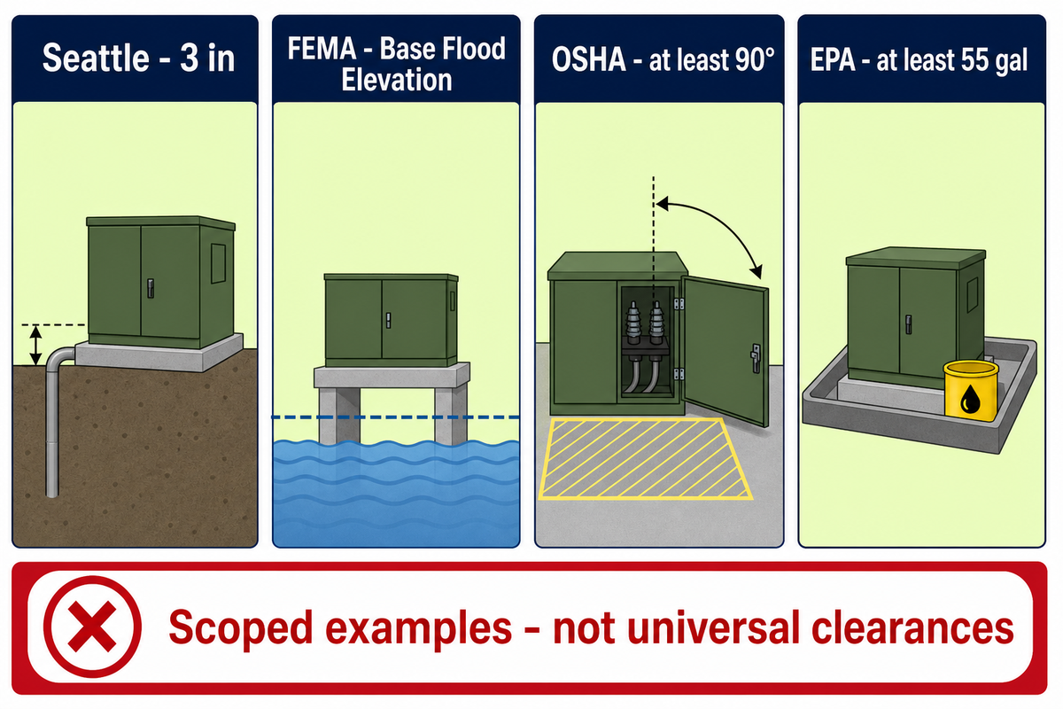
Civil coordination joins equipment-specific geometry to site-specific requirements. Concrete pad footprint, base opening, anchoring, conduit entry, door travel, vehicle exposure, flood elevation, access, drainage, and oil controls may come from different records; a copied online pad detail cannot prove that those inputs align.
One named Seattle City Light standard requires conduit to project 3 in above the pad within its stated public-property service scope. That number belongs to the Seattle document and its project package; it is evidence that local requirements can be specific, not a value to repeat on another utility’s drawing.
Site conditions can add a second layer. FEMA flood-mitigation guidance presents elevation of pad-mounted transformers above the Base Flood Elevation as a mitigation measure. OSHA 29 CFR 1926.403, within its construction-rule scope, addresses protection from physical damage, working space, and clearance for doors or hinged panels to open at least 90°.
Environmental review may also be conditional. EPA guidance for oil-filled operating equipment explains that equipment holding at least 55 gal is counted in a facility-level spill-prevention applicability calculation. The facility location, aggregate storage, and discharge risk still matter, so 55 gal is not a stand-alone verdict for every transformer.
Boundary to carry into the drawing review
Three scoped examples, 3 in, 90°, and 55 gal, prove that multiple authorities may contribute project inputs. None is a universal pad-mounted-transformer clearance.
Review Before Specifying a Utility Transformer
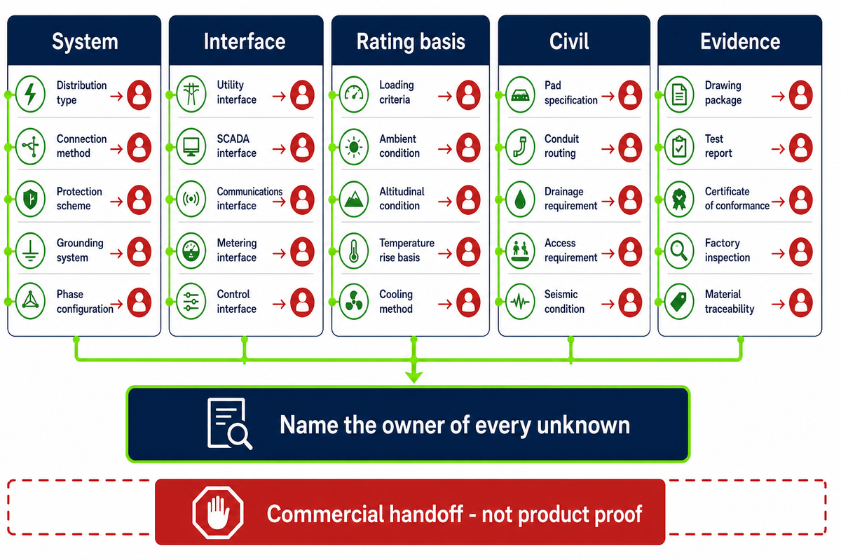
Supplier conversations should start only after the known and unknown fields are separated. Buyers need a system one-line, voltage and phase basis, feed and interface description, rating basis, civil package, utility requirements, submittal scope, and a named owner for final approval; generic diagrams cannot fill those fields.
Document-readiness gate
- System: grid role, approved one-line, primary and secondary voltage, phase, and frequency.
- Interface: radial or loop feed, stated high-voltage interface, terminal requirements, and utility ownership boundary.
- Rating basis: required kVA or MVA basis, load information, impedance need, taps where stated, and applicable standard scope.
- Civil: footprint envelope, pad and anchoring inputs, conduit zone, access, flood condition, vehicle exposure, and fluid controls where relevant.
- Evidence: outline drawing, connection record, nameplate fields, test and submittal expectations, revision owner, and approval owner.
Situations That Require Project Records
Set the generic diagram aside when the project record is missing, two revisions disagree, a single-phase request is being checked only against a three-phase scope, or a site condition has no owner. The same rule applies when an accessory appears in an illustration but has no manufacturer sheet behind it.
Dimensions copied from another utility, cabinets that “look like” loop feed, or matching kVA values do not close an approval gap. Procurement should pause the affected field, name the responsible party, and request the record that can answer it.
Once the document-readiness gate is complete, the buyer can use the Talite utility transformer documentation review as a commercial handoff. That link is not evidence of a rating, certification, lead time, standard conformance, or project result; those points need project-specific confirmation.
Key takeaway
A useful transformer review aligns five document layers, three identity records, and every site-specific input before a generic picture becomes a project decision.
Request a Project-Specific Document Check
Send the one-line, equipment schedule, utility package, and the latest manufacturer drawing. The Talite distribution transformer buying paths can frame the product route while the project records define what still needs confirmation.
Frequently Asked Questions
What does a pad mounted transformer diagram show?
Pad-mounted transformer diagrams may show physical zones, electrical relationships, connection identifiers, dimensions, or nameplate data, depending on the record type and its stated purpose for that project.
Those functions belong to different record types. Check the title block, drawing number, revision, legend, and notes before interpreting any symbol. Generic pictures are useful for orientation, while the approved one-line, manufacturer drawing, nameplate, and applicable utility package control the project review. When two records disagree, log the field and its owner instead of selecting the more convenient value.
What are the main parts of a pad-mounted transformer?
Major zones can include the tank, core-and-coil assembly, primary and secondary compartments, bushings, terminals, protective interfaces, switches, and grounding provisions shown for a specific unit.
The exact arrangement changes with the phase family, feed design, voltage class, manufacturer, and project. Indicators or accessories should be named only when the unit-specific record shows them. Read a conceptual cutaway as a function map, not proof that a component is present in the same place on every unit.
What is the difference between single-phase and three-phase pad-mounted transformer diagrams?
Single-phase diagrams represent one phase relationship, while three-phase diagrams must represent three phase relationships and their stated winding or terminal connections for the named equipment.
Current IEEE public scopes separate the families: C57.12.38-2025 covers its stated single-phase units at 250 kVA or smaller, while C57.12.34-2022 covers its stated three-phase units at 10 MVA or smaller. The records can also differ in terminal labels, voltage presentation, winding relationships, feed arrangement, and the notes attached to each symbol. Compare the diagram against the equipment schedule and nameplate, then confirm which utility and project documents govern. These scope limits do not constitute a field connection instruction or a Talite product rating.
Is a transformer diagram the same as a wiring diagram?
Transformer diagrams are not necessarily field wiring drawings.
The phrase can refer to a cutaway, one-line, schematic, connection plate, general arrangement, or civil sheet. It doesn’t authorize cable preparation, enclosure access, switching, testing, or energization; qualified parties and approved records govern that work.
How close can a pad-mounted transformer be to a building?
No single distance can answer every pad-mounted-transformer project.
The applicable utility standard, equipment design, building and fire rules, doors and windows, access, vehicle exposure, flood condition, ventilation, and fluid controls may all affect the approved location. Use the current civil package and the requirements named for that site; don’t copy a distance from an unrelated online drawing.
Are pad-mounted transformers still used?
Pad-mounted transformers remain part of underground distribution and facility power systems where an approved service design calls for their specific mounting and interface arrangement in practice.
They can be single phase or three phase and can differ in feed, interface, rating, and civil requirements. Continued use does not make an older generic drawing current. The equipment record, utility package, and approved project design still need to be checked for the specific installation.
References and Sources
- IEEE C57.12.34-2022, three-phase pad-mounted transformer public scope
- IEEE C57.12.38-2025, single-phase pad-mounted transformer public scope
- IEEE C57.12.28-2023, enclosure-integrity public scope
- City of Healdsburg, transformer specification and final drawing package
- USDA RUS Bulletin 1728F-806, underground distribution drawings
- USACE ER 1110-345-700, design records, revisions, and submittals
- FEMA IS-1023, electrical-system flood mitigation
- OSHA 29 CFR 1926.403, equipment and working-space provisions
- EPA, oil-filled equipment and facility-level SPCC applicability
Scope and Review Method
The guide treats a pad mounted transformer diagram as a document-reading problem, not a field-work instruction. Current public standard scopes, government records, and named municipal examples were checked against the article’s phase, revision, and civil-interface boundaries.
Company-provided background states that Talite Transformer Co., Ltd., formerly Jiangsu Fangteng Industrial Co., Ltd., has worked in the power-equipment sector for more than 30 years. That background is not independent evidence of a product rating, certification, lead time, or project result.
![Pad-Mounted Transformer: How It Works [2026 Guide]](https://toplit-transformer.com/wp-content/uploads/2026/08/pad-mounted-transformer-guide-featured-150x150.png)

![Single Phase Pad Mounted Transformer Guide [2026]](https://toplit-transformer.com/wp-content/uploads/2026/08/single-phase-pad-mounted-transformer-guide-featured-1-150x150.png)