Get in touch with Talite Transformer Co., Ltd Company

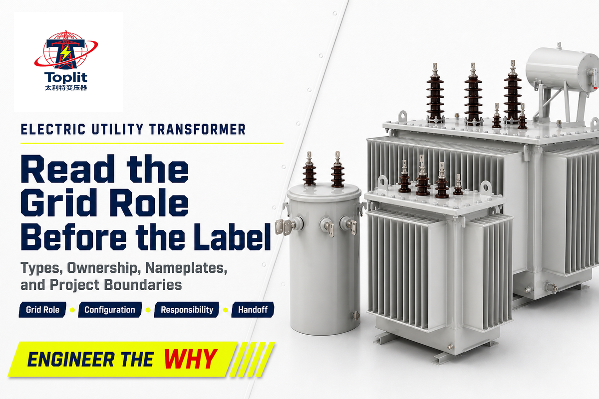
An electric utility transformer is a stationary alternating-current device that changes voltage at a defined point in a public or utility-connected power system. It may raise voltage for efficient bulk transfer or lower it as power moves toward local distribution and customer use, but the phrase itself is search-language shorthand, not a formal IEEE equipment class.
The practical questions are therefore about duty: Where does the unit sit, what voltage change does it perform, which configuration axes describe it, who controls it, and which records belong in a project handoff? This guide answers those questions without turning into a sizing calculation, protection study, product catalogue, or supplier comparison.
Start with the one-line diagramThe grid position and electrical duty identify the transformer more reliably than its enclosure, mounting style, owner, or an informal label.
Updated August 2026. Once a specification comes out, you need to cross-check existing standards, utility rules and project requirements again.
What Is an Electric Utility Transformer?
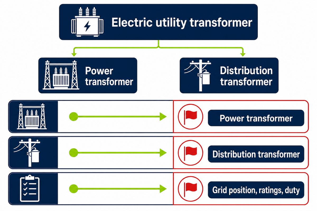
An electric utility transformer is a stationary alternating-current device used at a voltage-change point in a utility or utility-connected network. The exact equipment category comes from its grid position, ratings, duty and governing definitions, not from the focus phrase alone.
The physical assembly includes a magnetic core and at least two windings. It transfers electrical energy between circuits through electromagnetic induction while changing voltage and current relationships. In ordinary speech, “utility transformer” often means the distribution or service transformer seen near a load. In a wider grid discussion, it can also refer to a generator step-up or substation power transformer.
| Term | Useful meaning | Boundary |
|---|---|---|
| Electric utility transformer | Practical umbrella phrase based on utility-system use | Not a peer class defined by the phrase itself |
| Power transformer | Equipment identified by bulk-power or substation duty | Specification follows the actual system application |
| Distribution transformer | Equipment serving the distribution system, often at its final voltage-reduction stage | Regulatory scope varies by jurisdiction |
Public documentation for IEEE C57.12.80-2024 describes terminology for power and distribution transformers and associated apparatus. That scope is why this article uses the focus phrase as a reader-friendly umbrella while preserving the formal duty distinctions.
Follow the 4-Milepost Grid Map
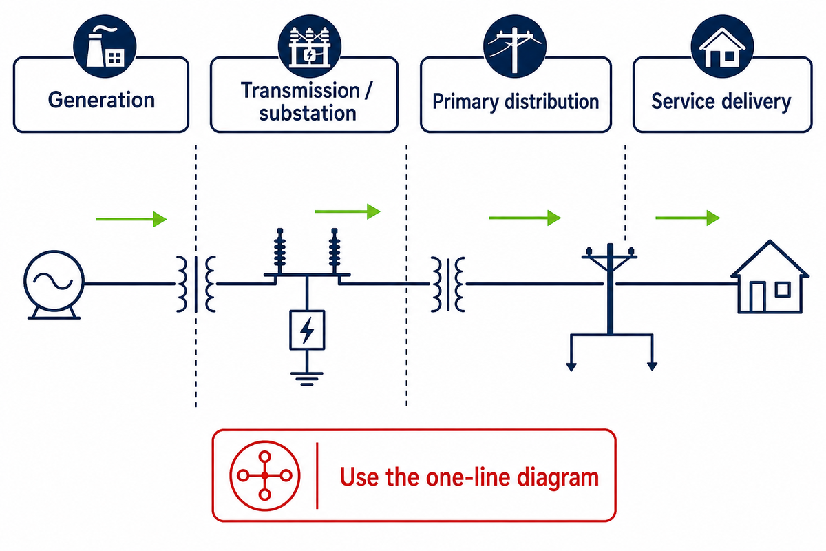
The 4-Milepost Grid Map follows each voltage-change point from generation to the final service. It’s a Talite editorial orientation heuristic, not an IEEE term, engineering calculation or utility rule. With the equipment labels separated, the map places each voltage-change duty along the grid.
1. Generation
Step up from generator output for bulk transfer.
Step up from generator output for bulk transfer.
2. Transmission / substation
Transform between network voltage levels.
Transform between network voltage levels.
3. Primary distribution
Feed local circuits and distribution zones.
Feed local circuits and distribution zones.
4. Service delivery
Reduce voltage toward utilization levels.
Reduce voltage toward utilization levels.
At the first milepost, a generator step-up transformer supports transfer onto a higher-voltage network. The U.S. Energy Information Administration overview of electricity delivery provides the public-system context: transmission lines move bulk power between generation and substations, where substation transformers may connect network levels and serve switching, protection and voltage-control arrangements. Farther downstream, distribution lines carry power through local distribution networks, and distribution transformers provide final voltage reduction for homes, commercial buildings and smaller industrial loads.
The broad chain from high voltage transfer to distribution voltage and customer service places each unit within the power grid and its power delivery path. Terms such as power distribution, electricity distribution, electrical power distribution and electric power distribution system describe that network context; none replaces the project one-line diagram.
The path isn’t a universal four-box topology. Networks can include multiple substations, network transformers, vaults, dedicated primary service, distributed generation and other arrangements. Use the approved one-line diagram and utility design documents to locate the real voltage-change point; don’t infer universal voltage values from a generic illustration.
How Does a Utility Transformer Change Voltage?
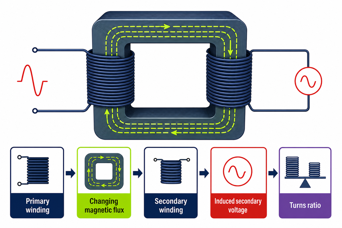
Current flowing through the primary winding produces an alternating magnetic flux in the core; this changing flux induces voltage in the secondary winding; the turns ratio of the windings determines the “ideal” voltage ratio. That relationship indicates whether the arrangement steps voltage up or down.
Conceptual chain
Alternating currentChanging magnetic fluxInduced secondary voltage
Step-up arrangements have more effective turns on the secondary side than on the primary; step-down arrangements have fewer. The primary and secondary windings illustrate the principle of electromagnetic induction, but that principle alone does not specify a finished unit; the public scope of IEEE C57.12.00 identifies a general-requirements standard for liquid-immersed distribution, power and regulating transformers. Power transfer also changes the current relationship, while winding resistance, core behavior, stray effects, auxiliary loads and cooling conditions create losses. The transformer changes voltage level; it doesn’t generate electrical energy.
What this explains
- Primary and secondary winding roles
- Why alternating flux is required
- Why turns ratio matters
What it does not calculate
- Required kilovolt-amperes
- Allowable loading or temperature rise
- Conductors, protection or fault duty
Real specifications therefore need far more than a turns ratio. System voltage, load basis, frequency, phase, vector or connection requirements, insulation duty, cooling, installation environment, utility practice and applicable standards remain separate inputs.
Main Utility Transformer Configurations at a Glance
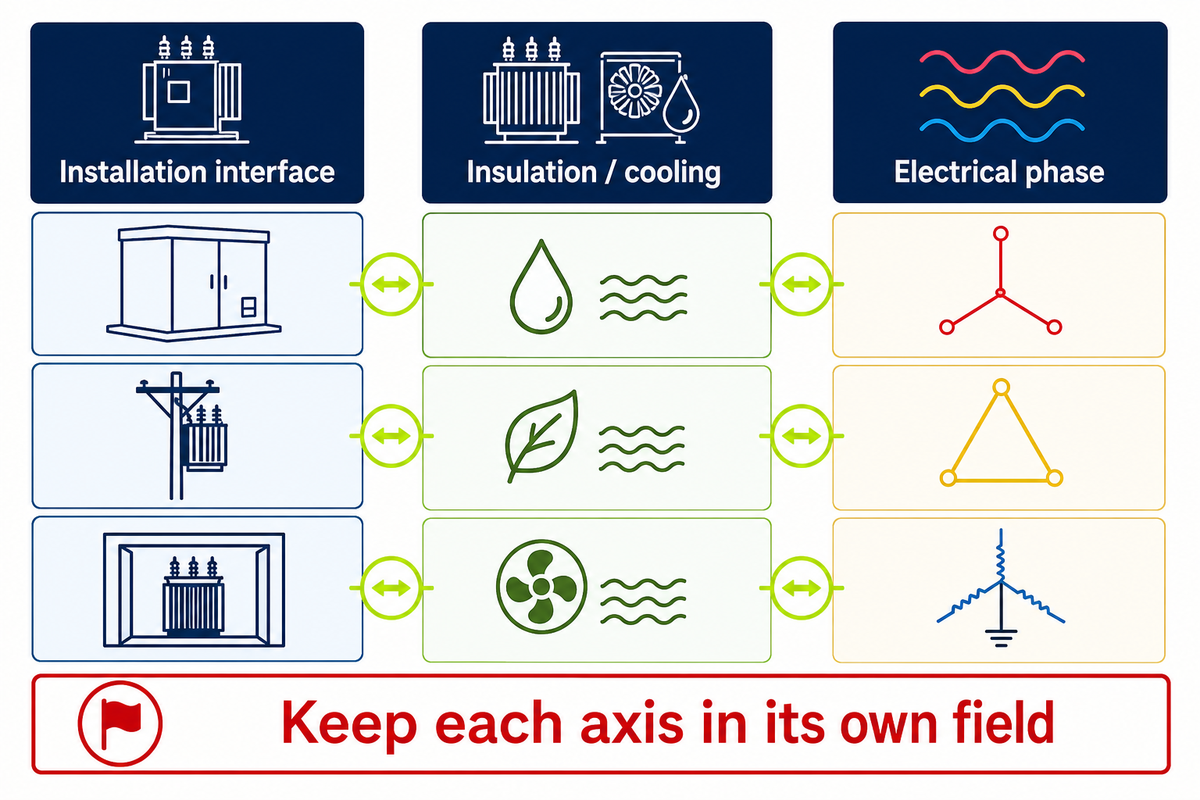
Transformer descriptions combine independent axes. Mounting isn’t phase, phase isn’t the insulation system, and none of those labels alone defines electrical duty. A complete record separates installation, insulation or cooling, phase, ratings and grid duty before configurations are compared.
| Axis | Common labels | What remains unresolved |
|---|---|---|
| Installation interface | Pole-mounted, pad-mounted, vault, substation | Phase, ratings, enclosure access and network duty |
| Insulation / cooling | Liquid-immersed, dry-type and more specific systems | Site suitability, thermal design and applicable requirements |
| Electrical phase | Single-phase, three-phase | Connection, load, voltage and grounding |
An overhead pole transformer is one installation form used in distribution networks. Overhead distribution commonly places pole-mounted transformers on a utility pole, while underground distribution commonly uses secured pad-mounted transformers. Those are orientation patterns, not universal selection rules. A data sheet may label service as “single phase,” while another project requires three-phase power; neither phase label reveals whether a unit is liquid-immersed or dry-type.
Network and substation context add further requirements around switching, access, protection, redundancy and service continuity. Detailed type selection, pole-versus-pad tradeoffs, capacity calculations and protection coordination belong in their dedicated engineering or procurement workstreams.
That separation matters during document control. Drawings may describe mounting, while a data sheet may state phase and cooling, a utility standard may control interfaces, and a purchase specification may bind the accepted combination. If a reviewer treats any one label as the whole configuration, two quotations can appear comparable while covering different duties. Keep each axis in its own field, record the governing document beside it, and mark unresolved entries as open rather than filling them from a familiar product description.
Utility Transformer vs Power Transformer vs Distribution Transformer
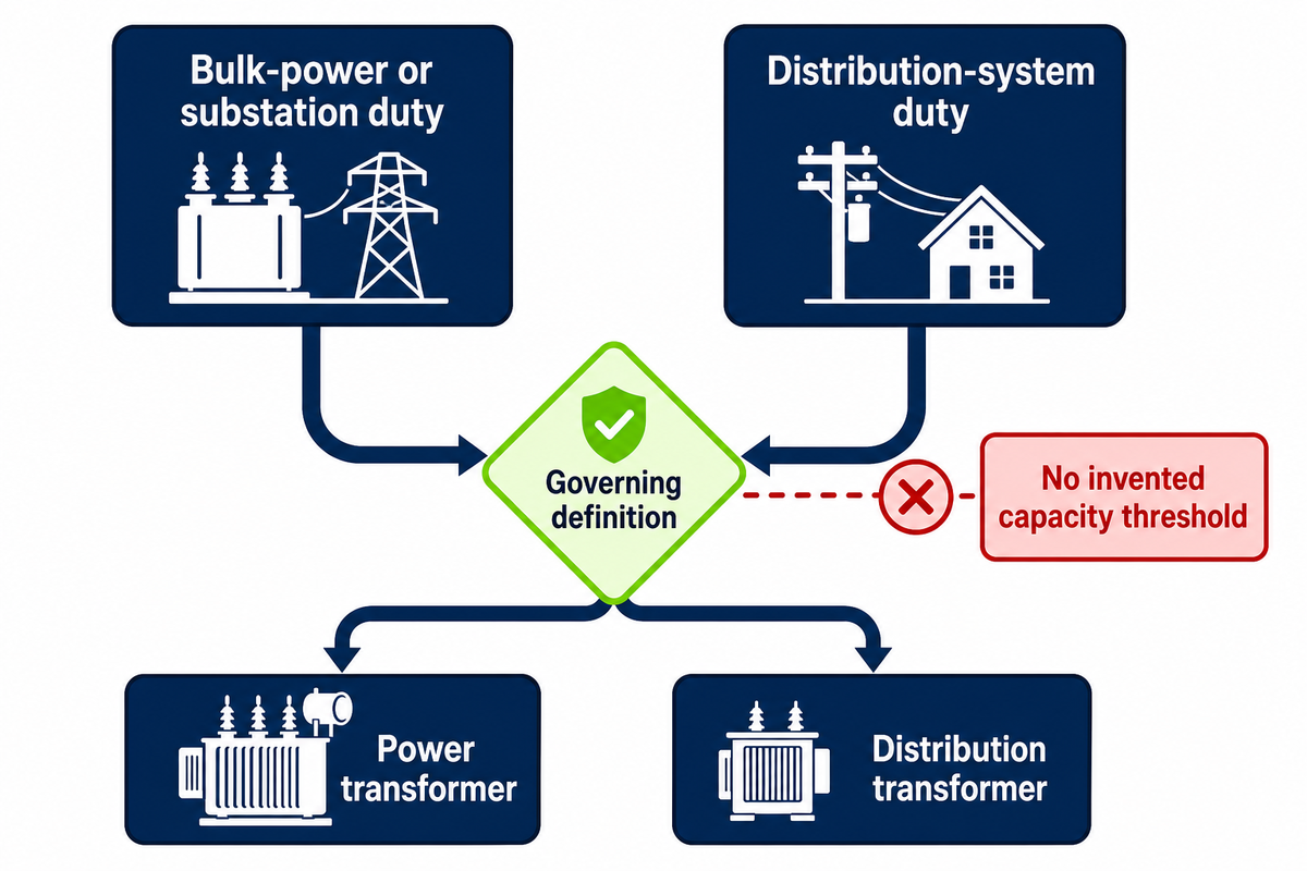
Utility transformer, power transformer and distribution transformer aren’t universal synonyms. “Electric utility transformer” describes context in everyday search language, while power-transformer and distribution-transformer labels point toward different grid duties and governing specifications. The project application and governing definition decide which label is appropriate.
Power transformers commonly serve bulk-power transfer or substation duty. Distribution transformers serve the distribution system and often perform the final voltage reduction toward end use. The dividing line should come from the system application and applicable standard, not an invented capacity threshold copied across jurisdictions.
The current electronic Code of Federal Regulations, 10 CFR 431.192, presents a U.S. efficiency-regulation scope with included and excluded equipment. It’s useful when that jurisdiction and rule apply, but it isn’t a global definition of every transformer used by a utility.
U.S. covered-scope example, not a global selection table
The current federal definition includes input line voltage of 34.5 kV or less, output line voltage of 600 V or less and operation at 60 Hz. It states capacity bands of 10 kVA to 5,000 kVA for liquid-immersed units and 15 kVA to 5,000 kVA for dry-type units.
Named exclusions include a specifically defined transformer with multiple full-rated-capacity voltage taps whose total range is at least 20% of the highest tap. The Department of Energy overview reports that compliance with the amended standards is required on and after April 23, 2029. These figures classify federal regulatory coverage; they don’t size a project or prove that a Talite configuration complies.
Decision rule
State the grid position, primary and secondary system levels, load relationship, duty and specification authority before assigning the product-family label.
Who Owns the Transformer? Use the Service-Point Responsibility Handshake
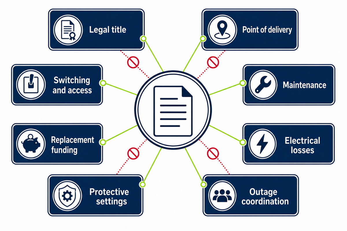
“Utility transformer” does not guarantee utility ownership. Legal title, point of delivery, metering, operating control, maintenance, replacement cost and electrical-loss allocation can be assigned differently by tariffs, service rules and written agreements. The controlling documents decide each field for a specific service.
The Service-Point Responsibility Handshake is a Talite editorial evidence checklist, not a recognized utility-governance method, tariff interpretation or legal conclusion. Its purpose is to stop one ambiguous word—“owner”—from hiding several separate decisions.
| Responsibility category | Possible evidence | Do not infer from |
|---|---|---|
| Who holds legal title? | Asset record, contract, tariff | Enclosure location |
| Where is the point of delivery? | Approved service design, service rules | Meter position alone |
| Who controls switching and access? | Operating agreement, safety rules | Asset title alone |
| Who maintains the equipment? | Maintenance or service agreement | Who normally visits the site |
| Who funds replacement? | Tariff and cost-allocation terms | Maintenance duty |
| Who bears electrical losses? | Billing rules and metering arrangement | Meter location |
| Who approves protective settings? | Protection study and utility approval | Transformer ownership |
| Who coordinates outages? | Operating procedure and emergency contacts | Routine access practice |
A useful official counterexample appears in Illinois Administrative Code Section 410.10. Its jurisdiction-specific definition states that the point of delivery is determined without regard to transformer, substation or meter location or ownership unless written contract or tariff provides otherwise. The lesson is not that every jurisdiction uses the Illinois rule; it is that service point and title must be checked separately.
How to Read a Nameplate for Project Handoff
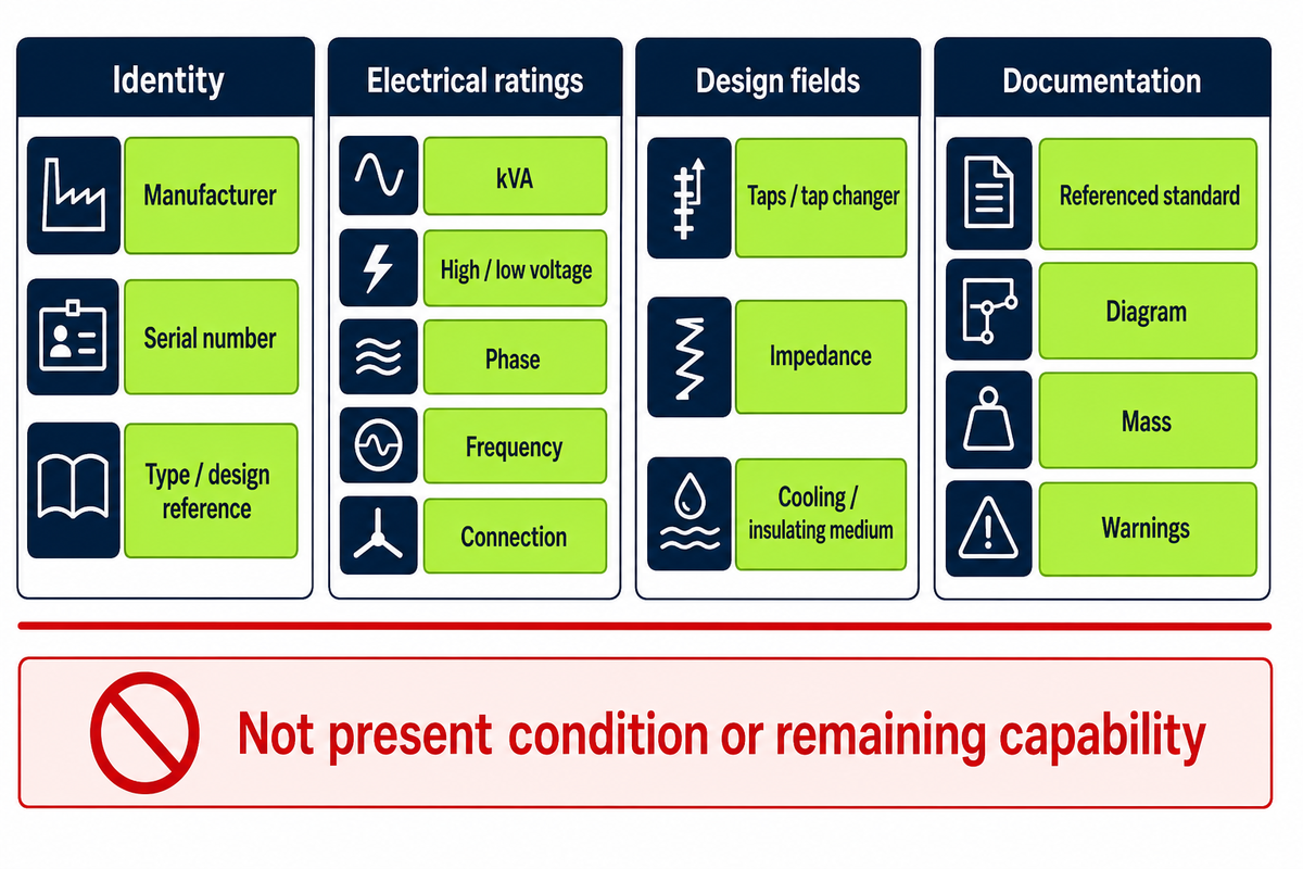
A transformer nameplate records identity and static ratings. It helps identify an existing unit or frame a replacement inquiry, but it doesn’t establish present condition, thermal age or remaining capability. Once the responsibility boundary is recorded, the nameplate provides the next set of asset-specific evidence.
Identity
Manufacturer, serial number, type or design reference
Manufacturer, serial number, type or design reference
Electrical ratings
kVA, high/low voltage, phase, frequency, connection
kVA, high/low voltage, phase, frequency, connection
Design fields
Taps or tap changer where stated, impedance where stated, cooling or insulating medium
Taps or tap changer where stated, impedance where stated, cooling or insulating medium
Documentation
Referenced standard, diagram, mass and warnings where provided
Referenced standard, diagram, mass and warnings where provided
Not every nameplate contains the same fields. Transcribe the plate exactly, photograph it only under the owner’s authorization and safe procedures, and reconcile it with the approved one-line diagram, drawings and manufacturer documents. Do not fill material fields from generic descriptions such as silicon steel or copper or aluminum wire; use documents for the specific unit. Never open an energized enclosure merely to collect data.
The public scope of IEEE C57.167-2023 considers transformer type, risk exposure, outage impact, unusual service conditions, installation location and monitoring parameters. Those inputs illustrate why condition decisions also need operating and loading history, fault exposure, maintenance, tests and monitoring records, not just a plate photograph.
The Lifecycle Load-Pressure Loop
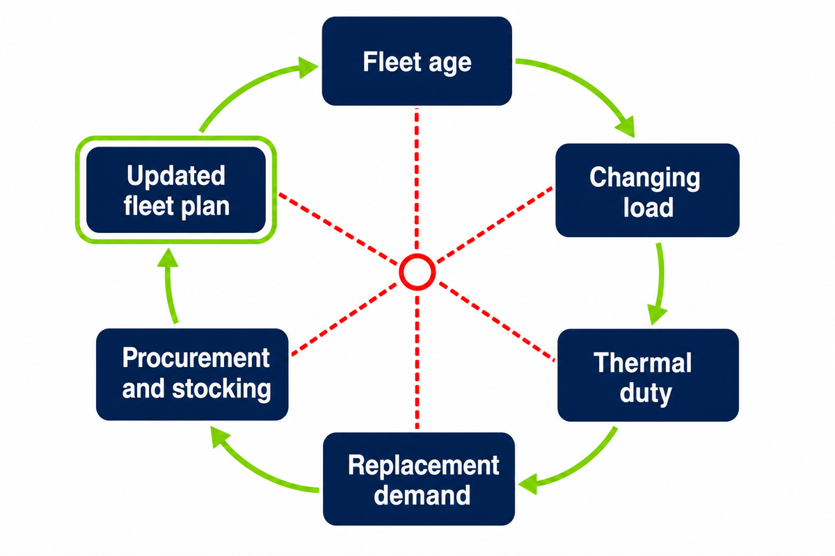
Fleet age, new load, thermal stress, replacement demand and supply planning interact. The Lifecycle Load-Pressure Loop is a Talite editorial planning synthesis, not an asset-health model, remaining-life calculation or industry standard. Nameplate data starts the record; loading and operating history show how the asset has been used over time.
Five connected planning pressuresFleet age → changing load → thermal duty → failure or replacement demand → procurement and stocking → updated fleet plan.
A 2024 National Renewable Energy Laboratory analysis reported that approximately 55% of the in-service U.S. distribution-transformer fleet was at least 33 years old. It also modeled U.S. distribution-transformer in-service capacity requirements in 2050 at up to 260% above 2021, depending on scenario.
Those numbers do not say that a 33-year-old unit has reached end of life. In a March 2026 U.S. Department of Energy webinar, the National Renewable Energy Laboratory discussion explained that lightly loaded units may accumulate less thermal aging and sometimes remain in service for 50, 60 or 70 years. Calendar age and thermal age can diverge.
| Evidence point | Source context | Proper use | Does not prove |
|---|---|---|---|
| 34.5 kV maximum input line voltage | 10 CFR 431.192 | U.S. covered-scope boundary | Project primary voltage |
| 600 V maximum output line voltage | 10 CFR 431.192 | U.S. covered-scope boundary | Required secondary voltage |
| 60 Hz operating frequency | 10 CFR 431.192 | U.S. covered-scope condition | A global frequency rule |
| 10–5,000 kVA liquid-immersed band | 10 CFR 431.192 | Regulatory coverage band | A project size |
| 15–5,000 kVA dry-type band | 10 CFR 431.192 | Regulatory coverage band | A project size |
| At least 20% total tap range | Named federal exclusion definition | Identify the stated exclusion boundary | A generic tap-selection rule |
| April 23, 2029 | Department of Energy overview | Amended-standard compliance date | Current Talite compliance |
| About 55% at least 33 years old | 2024 National Renewable Energy Laboratory analysis | U.S. fleet-planning context | Remaining life of one unit |
| 2050 capacity up to 260% above 2021 | National Renewable Energy Laboratory scenario | Scenario range | Certain forecast for one utility |
| Demand 41% above 2019; 2024 lead times one to two years or longer | March 2026 Department of Energy webinar | Dated U.S. supply-chain context | Talite lead-time claim |
Asset decisions should combine condition evidence, load forecast, outage consequence and replacement planning. The fleet figures concern U.S. distribution transformers; they do not describe every large power transformer or every transformer owned by a utility.
For an individual asset, the planning question is not simply “How old is it?” A useful review asks how the unit has been loaded, which unusual events it has experienced, what maintenance and test history exists, how critical its customers are, and what replacement path is practical. Those answers can support inspection, monitoring, stocking or replacement priorities, but they still require the utility’s own risk criteria and qualified engineering judgment.
From General Understanding to a Project Requirement
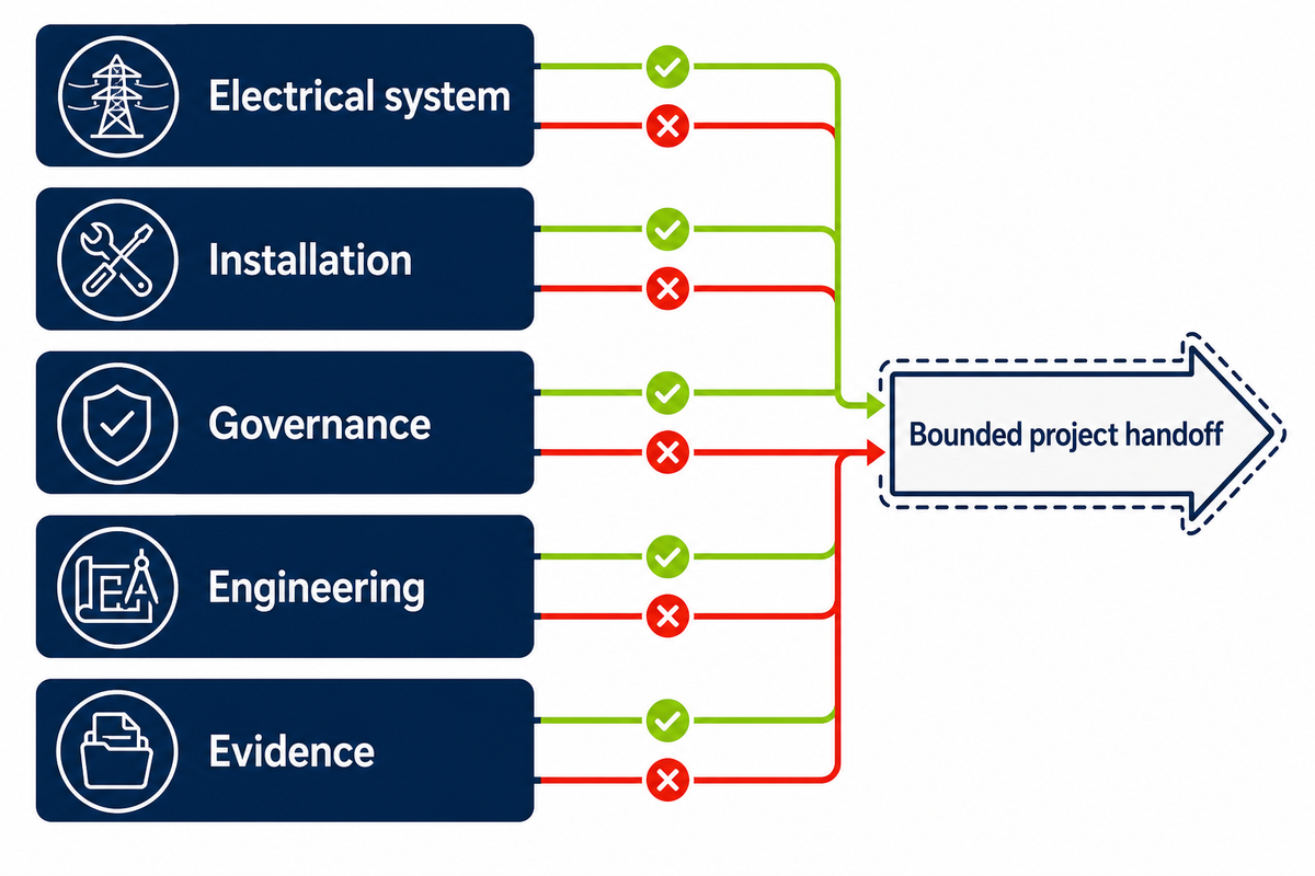
Move from education to a project discussion only after the system duty, installation interface, responsibility boundaries and unresolved engineering inputs have been recorded. A supplier inquiry cannot replace utility approval or project engineering. Together, the individual asset’s loading history, system duty and responsibility records form the basis of a bounded handoff.
| Input group | Record before inquiry |
|---|---|
| Electrical system | Primary and secondary voltage, phase, frequency, load basis, connection and grounding inputs |
| Installation | Indoor/outdoor environment, mounting or interface, access, climate and site constraints |
| Governance | Utility rules, applicable standards, point of delivery and separate responsibility fields |
| Engineering | Protection, insulation and study inputs supplied by the responsible engineer |
| Evidence | Requested drawings, data sheets, test documents, deviations and review status |
When those fields are ready, use Talite utility transformer solutions for the commercial project handoff. That page owns solution, product and inquiry intent; this guide remains the informational reference.
According to company-provided background, Talite Transformer Co., Ltd. has worked in the power-equipment sector for more than three decades, was originally established as Jiangsu Fangteng Industrial Co., Ltd., and integrates research, production and sales in Nantong, Jiangsu. This is attributed corporate context, not third-party proof of a specific rating, certification, capacity, price, delivery time or project result.
Frequently Asked Questions
What is a utility transformer?
A utility transformer changes alternating-current voltage at a defined point in a utility or utility-connected power system. Its exact role depends on grid position and duty.
Depending on grid position, it may step voltage up for efficient bulk transfer or step it down toward distribution and customer use. The phrase is practical search language rather than one formal peer equipment class. Confirm the actual category from the one-line diagram, voltage class, duty, ratings and applicable utility, regulatory or equipment definition.
Is a utility transformer the same as a distribution transformer?
Not always; distribution transformer is the more specific duty label. The distribution label identifies a grid duty, while utility transformer is broader wording used in search.
A distribution transformer serves the distribution system and commonly performs the final voltage reduction before electricity reaches homes, businesses or smaller industrial loads. “Utility transformer” can be used more broadly for transformers in utility service. In the United States, federal efficiency regulation also defines a covered distribution-transformer scope, so project documents should name the grid role and governing definition.
What are the main types of utility transformers?
Group configurations along independent axes instead of treating every label as a separate complete type. Installation, phase, and insulation or cooling remain separate classification axes.
Installation may be pole-mounted, pad-mounted, vault or substation based; insulation and cooling may be liquid-immersed or dry-type; and service may be single-phase or three-phase. A pad-mounted unit can be single- or three-phase, and phase does not determine the insulation system. Start with grid role and installation interface, then resolve the remaining electrical and environmental requirements.
Who owns the transformer serving a property?
Ownership depends on applicable utility rules and written agreements, not appearance or location. Tariffs, service rules, asset records, and contracts establish the actual responsibility boundary.
A nearby transformer may be utility-owned, customer-owned or part of a primary-service arrangement. Do not use the point of delivery or meter location as automatic proof of title. Confirm legal ownership, operating and switching control, authorized access, maintenance duty, replacement cost, electrical-loss allocation, metering and outage coordination as separate fields in the controlling documents.
Do residential homes have transformers?
Homes in residential areas are normally supplied through distribution transformers, and one unit may serve one or several premises. The local utility’s rules and the controlling service documents determine the arrangement and responsibility boundary.
The utility network determines the arrangement, capacity and responsibility boundary. Never open an enclosure or approach damaged equipment; report it to the local utility.
What information matters on a transformer nameplate?
Capture the identity, kVA, voltage, phase, frequency, connection, tap and other stated rating fields. The plate documents identity and ratings, but not present condition or remaining life.
Also record impedance where stated, the cooling or insulating medium, referenced standard, diagram, mass and warnings when present. Not every plate contains identical fields, and the applicable equipment standard and manufacturer document decide what should appear. Match the transcription to drawings, the approved one-line diagram and the correct unit identity. A photograph cannot prove loading history, fault exposure, maintenance quality, thermal age, present condition or remaining capability. Those decisions require authorized operating records, maintenance and test documents, condition-monitoring evidence and qualified review.
Ready for a bounded project review?
Bring the project handoff card, utility documents and unresolved engineering inputs. Talite can discuss product scope without treating this educational guide as a sizing study or utility approval.
References & Sources
- 10 CFR 431.192, Distribution Transformer Definitions Electronic Code of Federal Regulations
- Distribution Transformers U.S. Department of Energy
- Electricity Delivery to Consumers U.S. Energy Information Administration
- IEEE C57.12.00, General Requirements for Liquid-Immersed Distribution, Power, and Regulating Transformers IEEE Standards Association
- IEEE C57.12.80-2024, Standard Terminology for Power and Distribution Transformers IEEE Standards Association
- IEEE C57.12.20-2023, Overhead Distribution Transformer Scope IEEE Standards Association
- What Is Driving the Demand for Distribution Transformers? National Renewable Energy Laboratory
- Distribution Transformer Convening Webinar Transcript U.S. Department of Energy, March 2026
- Illinois Administrative Code Section 410.10, Definitions Illinois General Assembly
- IEEE C57.167-2023, Guide for Monitoring Distribution Transformers IEEE Standards Association
- Distribution Transformer Research Electric Power Research Institute
Editorial transparency: This guide was prepared from publicly visible government, standards-organization and research-institute materials. Firecrawl source-body archiving was unavailable in this run, so the research database doesn’t treat those pages as hash-verified reusable evidence. The named models are Talite editorial heuristics; they aren’t engineering standards, tariffs or asset-health calculations.
![Pad-Mounted Transformer: How It Works [2026 Guide]](https://toplit-transformer.com/wp-content/uploads/2026/08/pad-mounted-transformer-guide-featured-150x150.png)
![Single Phase Pad Mounted Transformer Guide [2026]](https://toplit-transformer.com/wp-content/uploads/2026/08/single-phase-pad-mounted-transformer-guide-featured-1-150x150.png)