Get in touch with Toplit Transformer Co., Ltd Company

Solutions
Outdoor Prefabricated Compact Substation Solutions
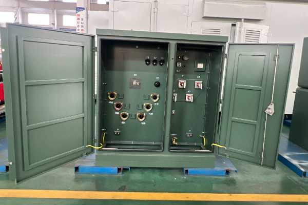
An outdoor prefabricated compact substation brings transformer, switchgear, control, protection, metering and enclosure decisions into one project boundary. Talite helps EPC, utility and industrial buyers turn electrical requirements and site conditions into a comparable RFQ.
Talite Outdoor Substation Capability at a Glance
A useful starting point is not a generic catalogue rating. It is a shared definition of the electrical duty, site interfaces, enclosure environment and handover scope.
Electrical basis
We record incoming voltage, frequency, transformer duty, outgoing system and protection assumptions before configuration.
Site basis
We review ambient conditions, altitude, pollution, solar exposure, cable entry, maintenance access and transport limits as project inputs.
Commercial basis
We separate included equipment, site work, documents, testing, logistics and commissioning responsibilities so quotations can be read on the same basis.
Handover basis
We map drawings, inspection points, interface owners and handover records before the order scope is frozen.
How to use this page
- First, define the ten input groups in the specification table.
- Next, compare every supplier against the same eight commercial scope groups.
- Then, assign one accountable owner to each site interface before the configuration is approved.
Outdoor Prefabricated Substation Configuration Scope
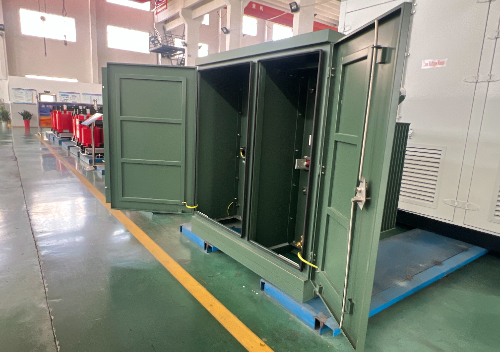
A prefabricated substation is an enclosed power distribution assembly; “package substation,” “containerized substation,” “outdoor compact,” and “type substation” can describe overlapping formats. The label alone does not define the equipment boundary.1 For the broader equipment-family boundary, review our prefabricated compact substation solutions.
-
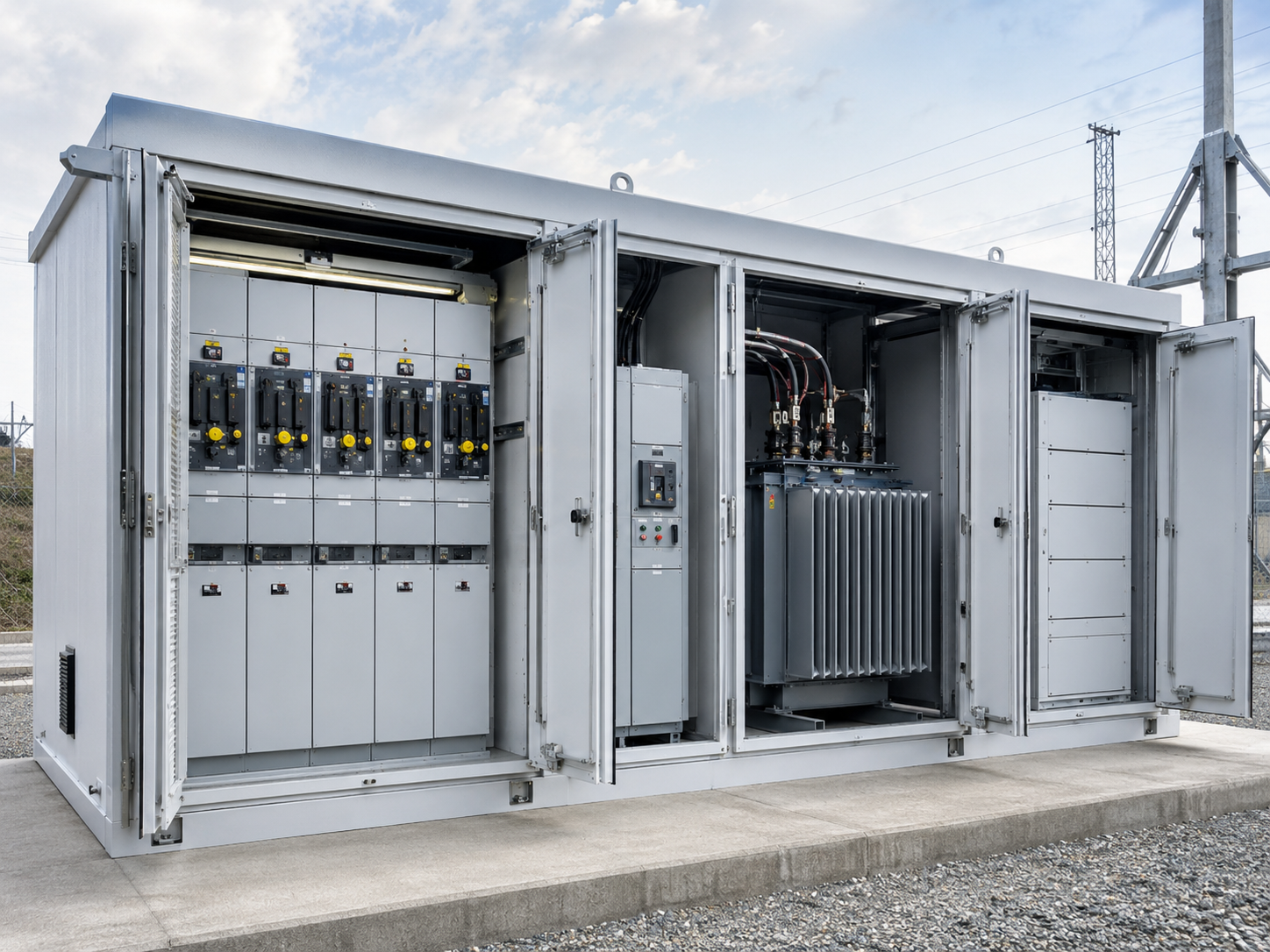
Medium-voltage side
Depending on the project, this side may call for medium-voltage switchgear, a ring main unit, ring main arrangement, load switch, fuse, circuit breaker, vacuum circuit breaker, relay, meter or other metering devices.
-
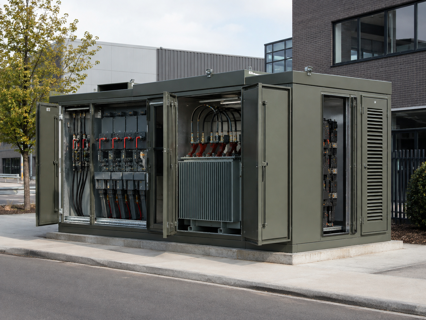
Transformer section
Transformer duty may involve a distribution transformer, power transformer, medium-voltage dry-type transformer or another type transformer selected against the grid and load profile.
-
Low-voltage and auxiliary side
Low-voltage or LV distribution equipment, control systems, auxiliary power supplies, wiring and outgoing cable interfaces must be stated rather than assumed.

-
Utility distribution
Distribution substations serving a utility grid need the network operator’s connection rules, protection settings and operating boundary stated early.
-
Industrial load
Industry and power plants may place more weight on motor starting, process continuity, maintainability and future feeder changes.
-
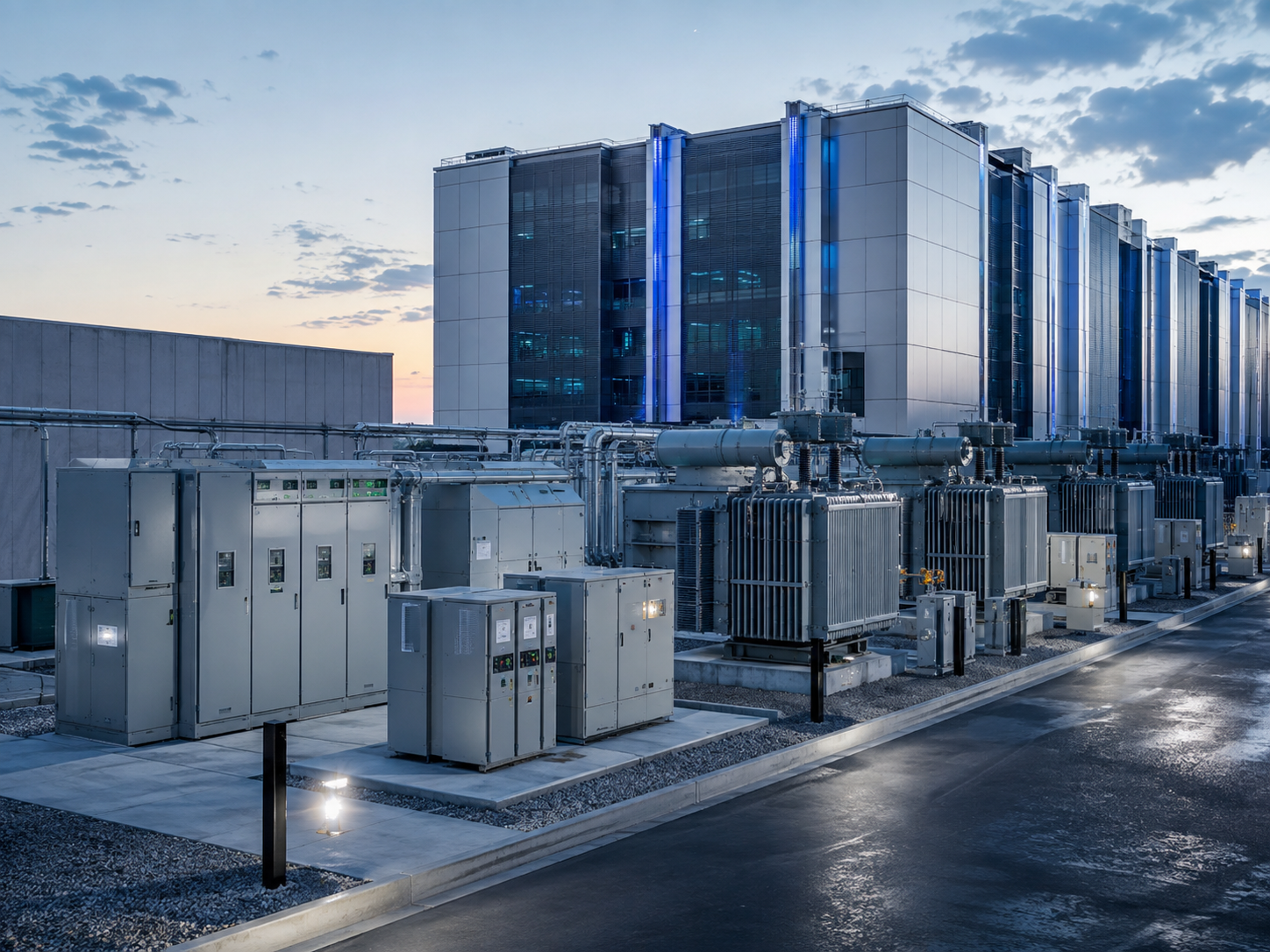
Digital infrastructure
A data center deployment may require a defined redundancy concept, auxiliary interface, monitoring list and staged energization plan.
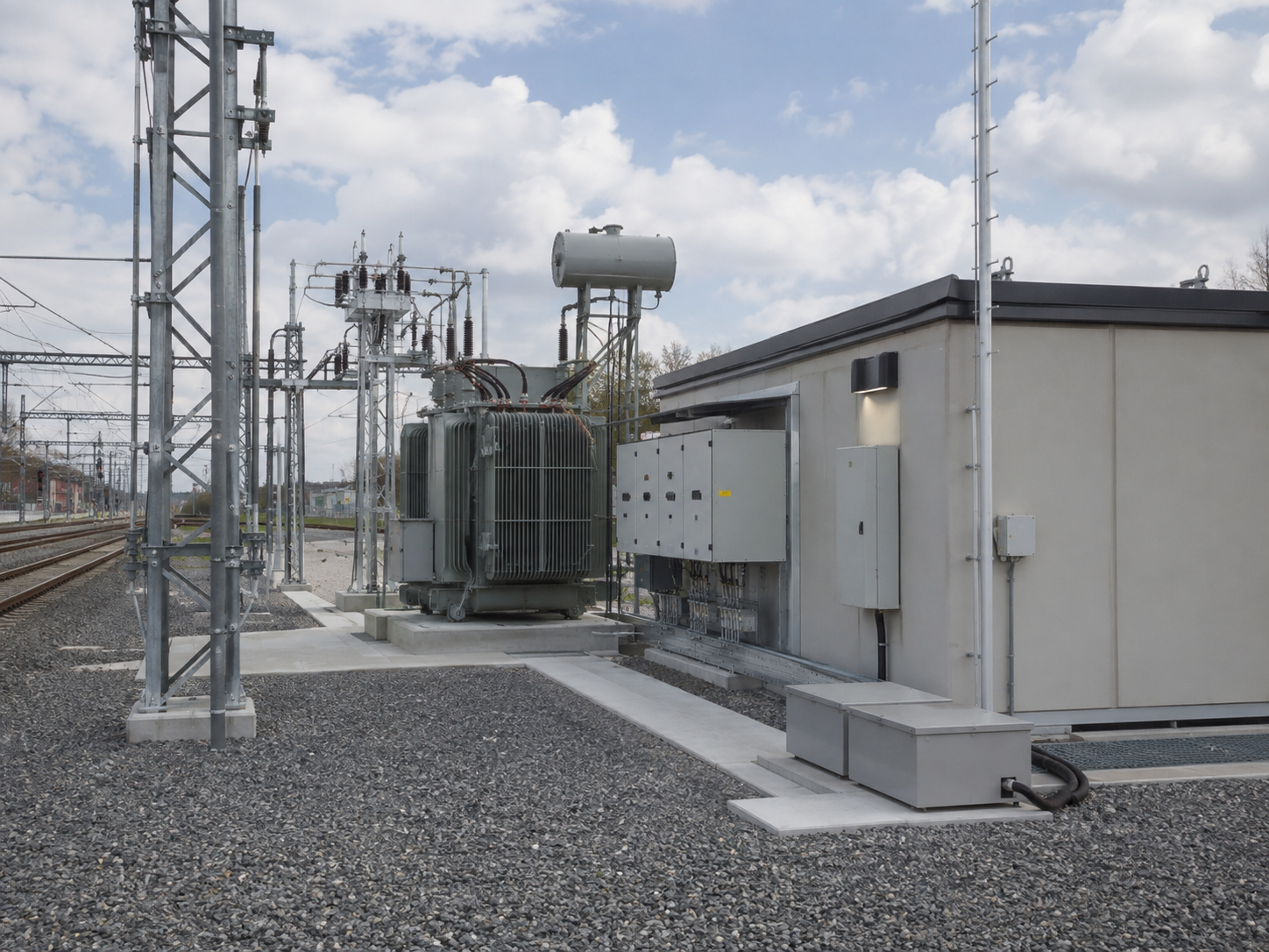
-
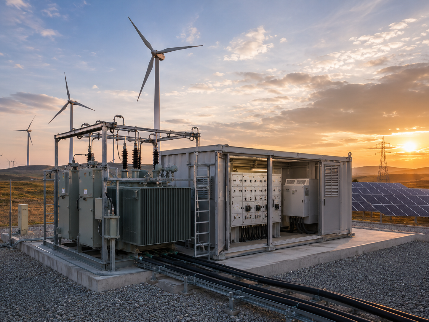
Transport and renewables
Railway, wind power and other renewable projects can add route, harmonics, remote-control or utility-interface questions to the same core intake.
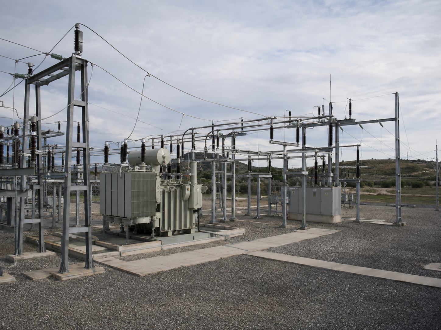
-
Terminology check
IEC 62271-202:2022 defines a current standard scope for AC prefabricated substations above 1 kV through 52 kV, including outdoor walk-in and non-walk-in arrangements. A project specification still needs to name its applicable standard, rated voltage and local authority requirements.
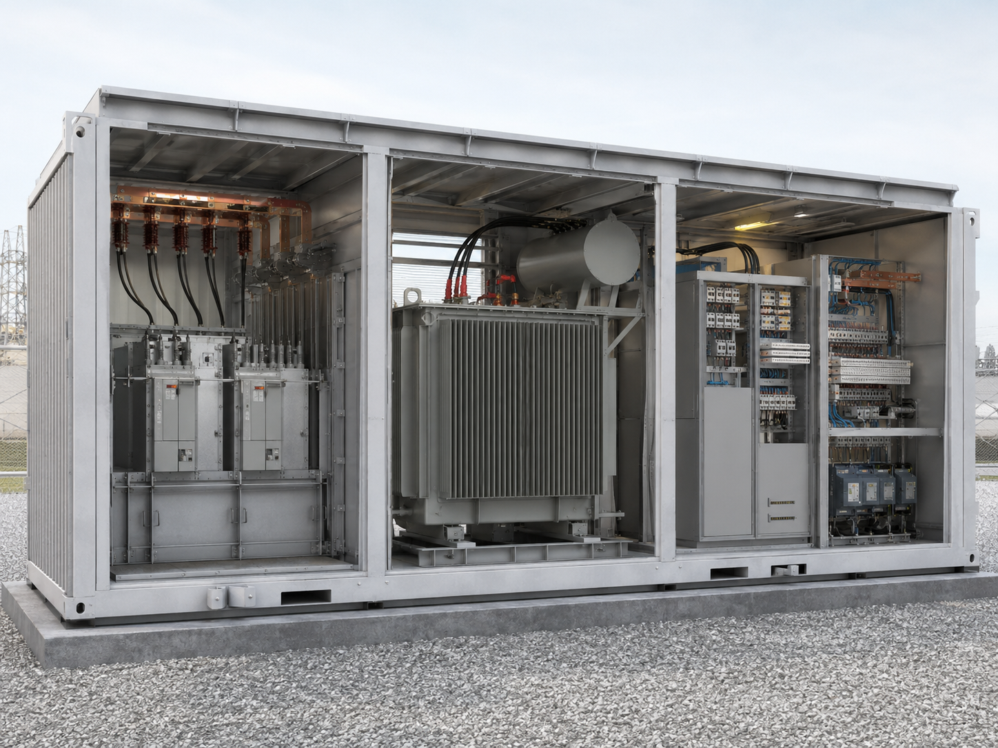
Enclosure and Environmental Configuration
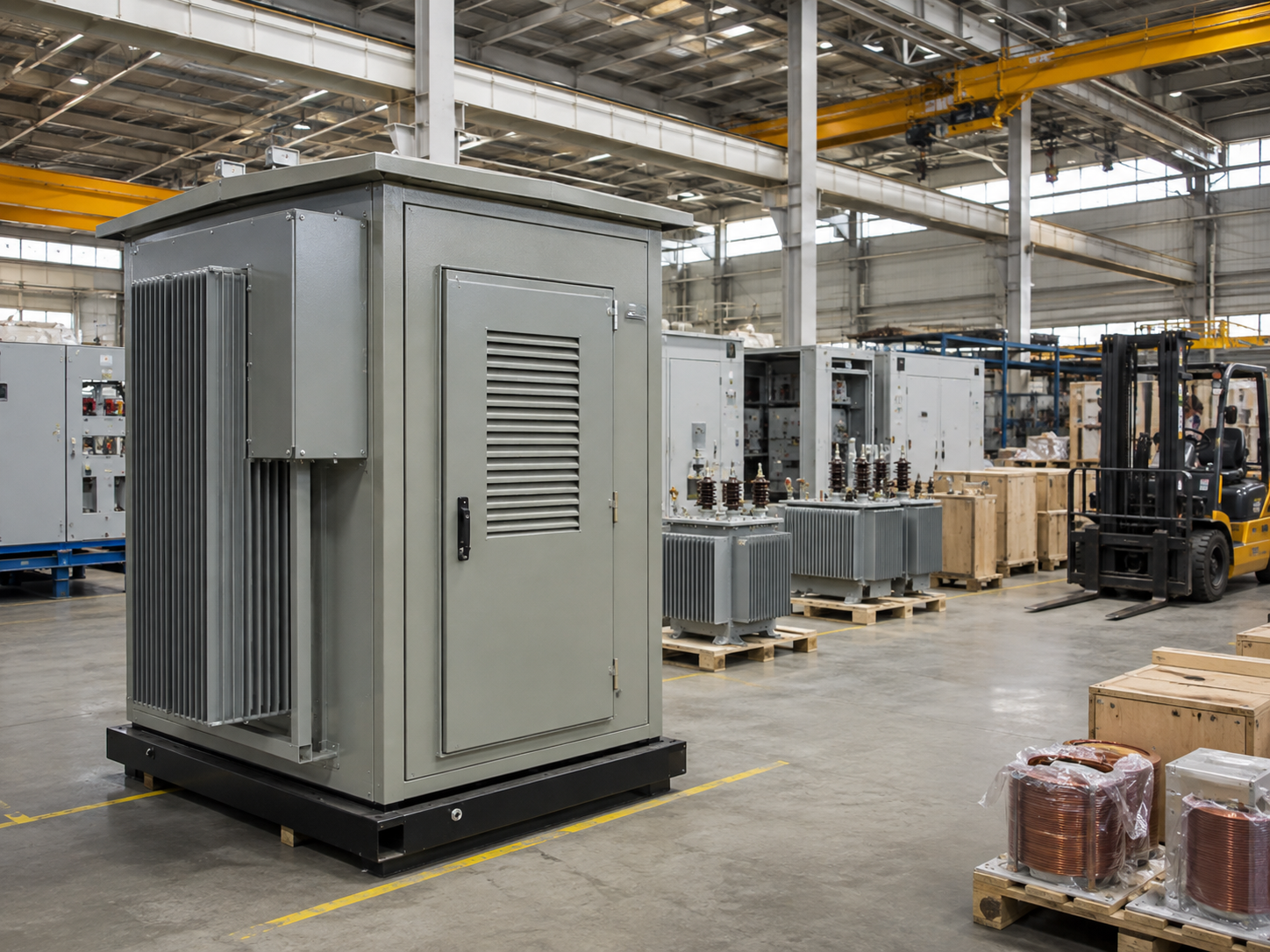
Outdoor protection begins with the enclosure as part of the electrical system, not decorative packaging. Its material, insulation, ingress protection, corrosion system, ventilation strategy and access arrangement must follow the site.1
Configuration Variables / 01
- Ambient temperature range, altitude and solar radiation
- Humidity, condensation risk and airborne pollution
- Wind, rain, dust, salt exposure and local weather events
- Public accessibility, security and authorized-person access
- Transformer fluid, fire strategy, drainage and containment criteria
Configuration Variables / 02
- HV, MV and LV cable approach and bending space
- Foundation level, trench geometry and grounding points
- Door swing, aisle, equipment removal and maintenance route
- Roof drainage, ventilation openings and heat dissipation path
- Lifting points, module splits and on-site assembly sequence
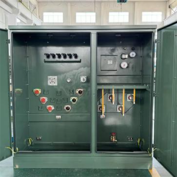
Process Warning
Catch the geometry conflict early
A layout can satisfy the electrical schedule and still fail the site when door swing, lifting, cable approach or civil datum information arrives late. Put those interfaces beside the electrical inputs before the enclosure arrangement is released.
Quality Verification
Boundary review before layout release
Factory design inputs and site design inputs must meet at named interface points. We record who supplies the cable and grounding data, who confirms drainage and fire criteria, and who accepts access and removal routes.
Outdoor Protection
and Thermal Management
Solar heat, internal losses and daily temperature swings affect electrical equipment and enclosure conditions. Design review should connect heat dissipation, ventilation, insulation and condensation control to the installed environment.1
“An enclosure decision is complete only when the electrical losses, outdoor exposure and maintenance route are reviewed together.”
Talite engineering workflow principle
-
01
Heat path
We identify heat sources, external solar load and the intended path from internal equipment to ambient air.
-
02
Moisture path
We review how air exchange, seals, pressure change and cold surfaces could create internal condensation.
-
03
Access path
We keep ventilation and environmental controls compatible with security, inspection and maintenance access.
Project Specification and Site Inputs
Use one input schedule for every bidder. This table is an RFQ structure, not a Talite product-rating table.
Example, not a catalogue limit
An 11kV utility scheme and a project at another kV class follow the same intake logic: state the actual system data, then select the high-voltage and low-voltage equipment around it.
| Input | Buyer information | Why it changes configuration |
|---|---|---|
| 1.Incoming system | Nominal and highest voltage, frequency, fault level, utility rules | Defines insulation coordination, switchgear and breaker duties |
| 2.Transformer duty | Required rating, load profile, overload philosophy, losses or efficiency criteria | Shapes transformer type, cooling and thermal review |
| 3.Outgoing distribution | Low voltage, feeders, distribution device arrangement and control philosophy | Sets LV board, wiring, protection and metering scope |
| 4.Protection and control | Relay functions, interlocks, communications and interface signals | Sets control systems, auxiliary supply and testing needs |
| 5.Grounding basis | Fault current, clearing time, soil data, grid and bonding responsibility2 | Supports step/touch review and connection design |
| 6.Environment | Temperature, altitude, humidity, pollution, solar and weather conditions | Shapes enclosure, insulation, ventilation and heat management |
| 7.Civil interface | Foundation, trench, cable entry, drainage and fire/spill criteria | Controls geometry and responsibility boundaries |
| 8.Logistics | Route, size and mass limits, lifting, unloading and module split | Controls how the assembly can be prefabricated, transported and installed |
| 9.Acceptance | Applicable IEC or local standards, inspections, tests and witness points | Defines records and hold points |
| 10.Handover | Drawings, manuals, spares, training and commission support | Sets the final supply and document boundary |
Pricing, Quotation and Lead-Time Drivers
No single public price or lead time represents every compact substation. A useful quotation explains which electrical, mechanical, document and site-work decisions are included.
- Transformer and switchgear type
- Protection, control and metering scope
- Enclosure environment and access mode
- Applicable standard and utility review
- Drawing and design-approval cycle
- Long-lead components and approved makes
- Inspection, witness and document stages
- Transport split and delivery-site constraints
- Civil work and grounding grid
- Site cable, termination and installation
- Fire/spill systems and drainage
- Energization, utility attendance and commission duties
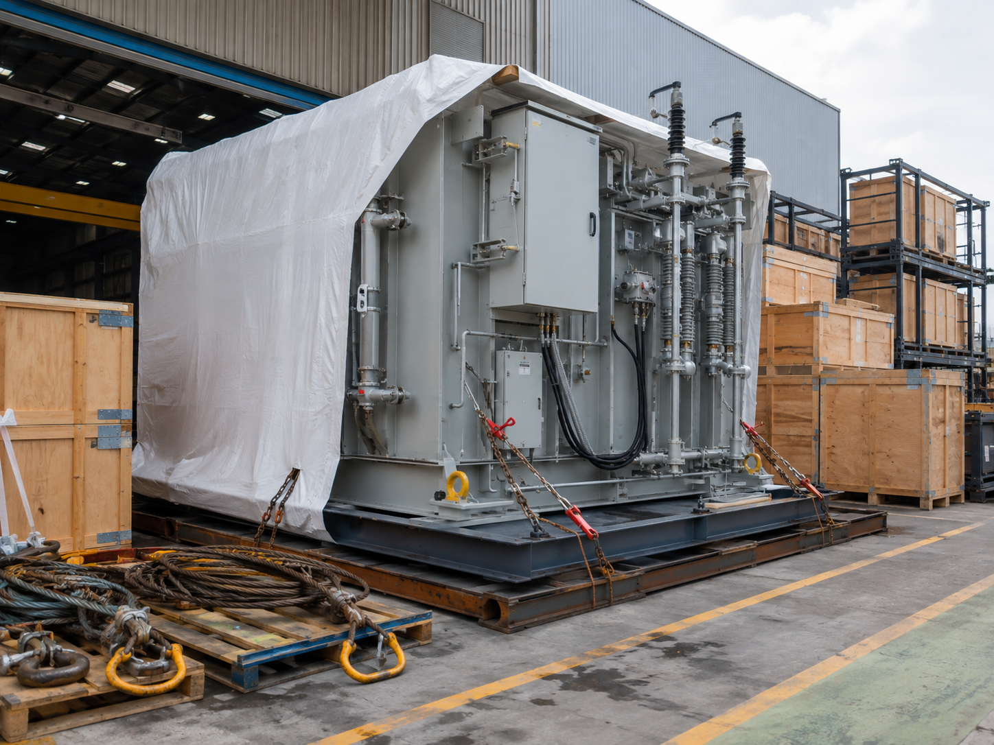
Parallel work needs a frozen interface
Freeze the commercial baseline
Keep change control visible
Factory assembly can proceed beside civil preparation only after equipment boundaries, cable entries, grounding points and release drawings are stable. Late changes don’t disappear in a prefabricated project; they move between factory work and site work.
Record the revision of the data sheet, single-line diagram and responsibility matrix used for the quotation. If one bidder carries a different revision, mark the difference before price and schedule are compared.
After order placement, connect each technical change to its drawing, supply-scope, document and site effect. This keeps a late interface decision from appearing as an unexplained equipment or delivery change.
Acceptance path
Quality Assurance — Engineering, Quality and Document Control
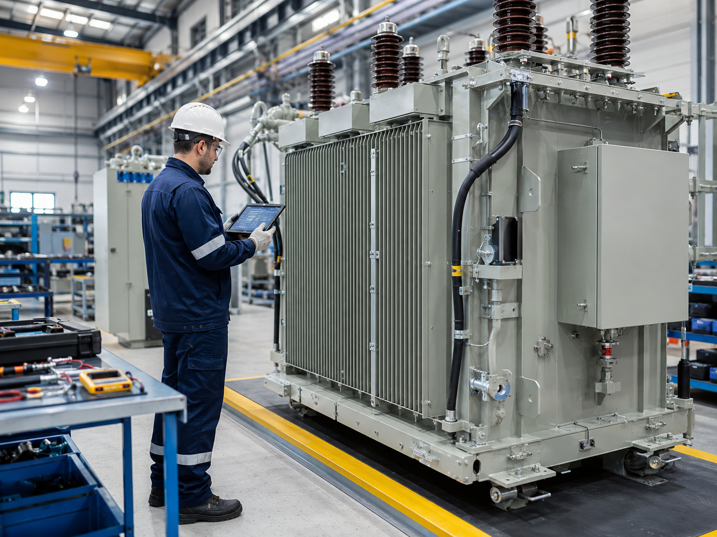
A standards reference is not a substitute for a project acceptance plan. We turn the approved specification into a list of drawings, reviews, inspection points, records and release conditions.

STAGE / 01
Design basis
We align the single-line diagram, equipment boundary, rated voltage, protection and environmental inputs.
STAGE / 02
Document register
We identify the drawings, data sheets, calculations, manuals and certificates required by the contract.
STAGE / 03
Inspection plan
We record review, witness and hold stages together with the evidence expected at each point.
STAGE / 04
Release pack
We reconcile approved documents, inspection records and shipping or handover requirements before release.
Inspection Hold Points
-
Before approval
Check that every rating and interface in the offer traces to an input, drawing or agreed assumption.
-
Before inspection
Check that the inspection plan names the item, method, acceptance basis, witness status and record to be issued.
-
Before shipment
Check that open design comments, packing split, lifting information, shipping records and site prerequisites have owners.
CRITICAL REQUIREMENT
Assign grounding responsibility
Grounding becomes a schedule risk when soil data, fault assumptions, bonding points and responsibility boundaries aren't assigned. The register keeps the buyer, utility, Talite and civil or EPC contractor aligned on the required input and accountable owner.
COMPLIANCE
Evidence rule
IEC, utility and project requirements define the requested basis. Product conformity, test results and certificates are established by the corresponding project records, not by a generic standards list.
How We Work: Configuration-to-Handover Workflow
Our Outdoor Substation Site-Interface Register keeps electrical, civil, utility and supplier responsibilities visible. It also gives the project team a place to record unresolved inputs before the design is frozen.
We confirm whether the required arrangement is prefabricated compact, package, modular or containerized and define the physical boundary.
We map grid, transformer substation, distribution network, grounding, cable, fire/spill and civil interfaces.
We freeze configuration, approved documents and responsibility owners at named review points.
We assemble the agreed records and trace open actions through installation and commissioning support.
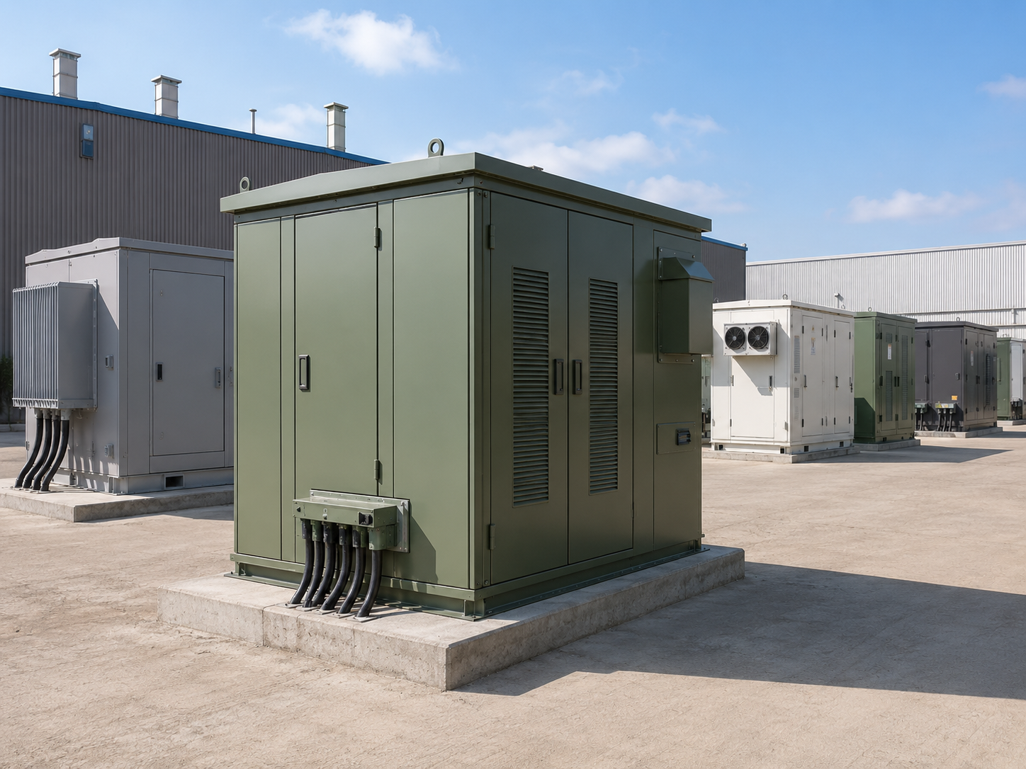
Talite Manufacturing Context
Talite Transformer Co., Ltd. has worked in the power equipment sector for more than three decades. Originally established as Jiangsu Fangteng Industrial Co., Ltd., the company is located in the Hai'an Economic and Technological Development Zone of Nantong, Jiangsu Province.
-
R&D, production and sales
Operating model
Talite operates as a high-tech enterprise integrating research and development, production, and sales.
-
Technology-led
Development approach
Talite follows a technology-driven development philosophy in the power equipment sector.
-
Power equipment
Sector focus
Company activity centers on transformer products and solutions for clients worldwide.
-
Evidence by contract
Project response
For an outdoor substation inquiry, the applicable product data, drawings, tests and documents are defined against the requested project scope.
Configuration Trade-Offs and Alternative Layouts
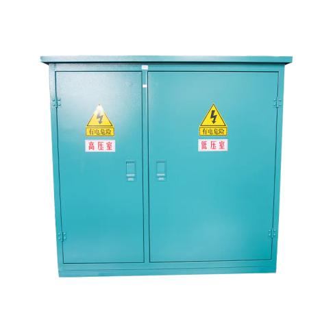
A modular or prefabricated compact layout is not automatically the best choice for every power substation. Very large, highly bespoke, unusual-geometry or tightly constrained brownfield work may favor a conventional site-built arrangement.1
Project condition
Format to examine
Decision test
Defined boundary, repeatable interfaces, limited site labor
Prefabricated compact or package
Can the assembly and site work proceed in parallel without hiding interfaces?
Shelter, auxiliary systems or transportable room is central
Containerized
Do transport, thermal, lifting and cable-entry limits fit the complete container?
Major expansion, unusual geometry or deep brownfield integration
Conventional or hybrid
Would a fixed module force excessive compromise in access, phasing or future extension?
Renewable, wind power, data center, railway, utility, industry or power plants
Application-specific review
Which load, grid, availability and maintenance requirements actually control the layout?
Prefabricated Compact Substation Engineering Tools
Outdoor Substation RFQ Input Check
Standardize your Request for Quotation parameters. Ensure all technical specifications for your outdoor substation are complete before supplier submission.
Access Tool
Supplier Scope Normalizer
Align and compare multiple vendor proposals seamlessly. Identify gaps in technical offerings and commercial boundaries for compact substations.
Access Tool
Site-Interface Responsibility Register
Clarify civil, electrical, and mechanical interface boundaries. Prevent installation delays by defining exact contractor responsibilities on-site.
Access Tool
Procurement questions
FAQ: Outdoor Substation Procurement
Include the single-line diagram, voltage and frequency, transformer duty, protection philosophy, fault and grounding basis, environment, civil and cable interfaces, logistics limits, acceptance requirements and document register.
Not always. Market terms overlap, so compare the actual transformer, switchgear, enclosure, auxiliary and site-interface boundary rather than the label.
Rating selection follows the load study, operating profile, system voltage, protection basis, environment and allowed future margin. Record the selection basis in the project specification.
Fault current, clearing time, soil data, bonding and conductive objects affect the grounding study and step/touch exposure review. Early ownership avoids a gap between the equipment and site grid.
Temperature, altitude, solar radiation, humidity, pollution, wind, rain, dust, salt, security and access can change the material, insulation, ventilation, heat and moisture strategy.
Confirm the transformer fluid, project fire strategy, separation or barrier needs, containment, drainage and lightning criteria with the responsible authority. Don't import a generic distance or volume threshold into a different jurisdiction.
It can shift selected assembly and wiring tasks away from the site when the interfaces are defined early. Results still depend on foundation, cable, grounding, lifting, installation and utility responsibilities.
Issue one data sheet, then normalize included equipment, civil and site work, documents, tests, logistics, spares, training and commissioning duties. Resolve every unclear exclusion before comparing price.
Agree the drawing list, data sheets, calculations, inspection and test plan, records, manuals, certificates, spare-parts list and handover requirements that apply to the contract.
Consider it when scale, customization, geometry, brownfield phasing, future expansion or access needs make a fixed prefabricated boundary less practical. A hybrid layout may also separate repeatable modules from site-specific work.