Get in touch with Toplit Transformer Co., Ltd Company

Oil-Immersed Distribution Transformers for Project-Specific Power Distribution
Talite reviews the rated power, voltage level, winding connection, losses, impedance, site conditions and approval-document scope for an S11-M or S13-M oil-immersed distribution transformer. That review produces a proposal with stated assumptions, not a catalogue entry presented as the correct project fit.
Start a Technical Proposal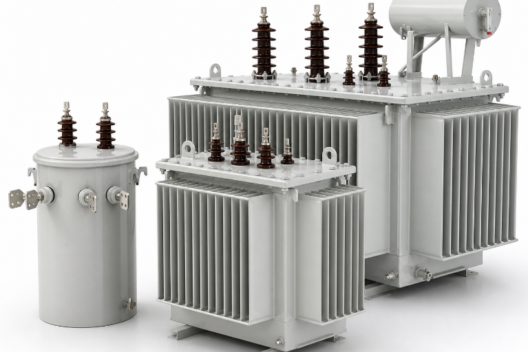
Review Model Data
30–3150 kVA
supplied 10 kV-class table
35 / 38.5 kV
global-project high-voltage table
Yyn0 / Dyn11
model-dependent vector groups
−25 to +40°C
supplied normal ambient range
Match the S11 or S13 Transformer Family to Your Project
Capacity shown in a file name isn’t part of the approved rating. Talite engineers the proposal from the actual model schedule; the 35 kV table stops at the last extractable 2500 kVA row rather than assuming an unlisted 3150 kVA option.
Catalogue data is a starting point. A suitable transformer is the model whose electrical duty, site boundary and evidence pack all agree.
Authority context: For a U.S. destination review, the Federal Register distribution-transformer rulemaking defines category and compliance boundaries; it doesn’t certify this Talite series.
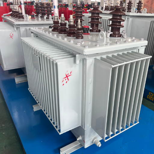
S11-M / S13-M Sealed Series
- Rated capacity30–3150 kVA
- High voltage6, 6.3 or 10 kV
- Low voltage0.4 kV
- Tap range±5% or ±2 × 2.5%, model-dependent
- Vector groupYyn0 or Dyn11, model-dependent
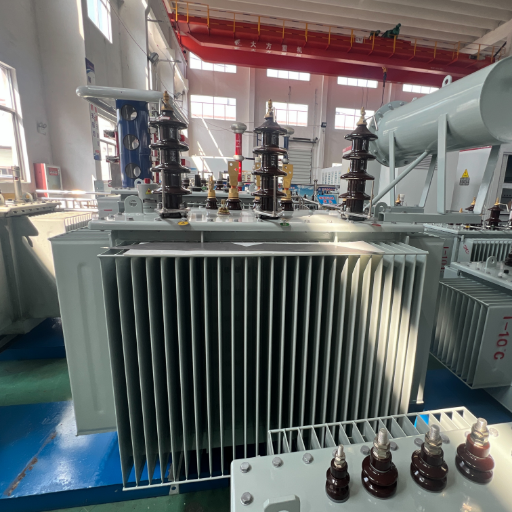
S13 35 kV-Class Series
- Extracted table range50–2500 kVA
- High voltage35 or 38.5 kV
- Low voltage0.4 kV
- Vector groupDyn11 or Yyn0
- Short-circuit impedance6.5% (in the supplied table)
Destination-Market Specification Alignment Grid
| Buyer input | Talite data to match | Evidence before approval | Decision state |
|---|---|---|---|
| Rated capacity and load profile | Model kVA and loss schedule | Approved data sheet | Match / confirm |
| Primary and secondary voltage | Supplied voltage tables | Electrical schedule | Match / custom review |
| Frequency, phase and power quality | Project requirement | Nameplate and study basis | Confirm |
| Vector group and tap range | Model configuration | Wiring diagram | Match / confirm |
| Impedance and fault duty | Model impedance | Short-circuit study | Engineering review |
| Ambient, altitude and access | Normal-service boundary | Site data | Match / derating review |
| Destination standard | Proposed product category | Current scope and records | Documentary review |
| Accessories and monitoring | Option schedule | Approved accessory list | Confirm |
- A quote can match kVA but omit the correct voltage, reference condition or loss basis.
- Another transformer design becomes the unsupported basis for vector group, tap range or conductor.
- A 35 / 38.5 kV global table is treated as U.S. applicability evidence without category and test-scope review.
- A standard name or certificate logo appears without a current model and scope document.
- Searches for “oil immersed transformers” can mix mounting arrangements, voltage classes and cooling systems.
- An “oil filled distribution transformer” request must state whether the duty is single-phase or three-phase.
- A “three phase oil immersed transformer” search still needs voltage, vector group, impedance and site boundaries.
- An “oil immersed transformer manufacturer” comparison needs the same evidence and commercial scope for every supplier.
Turn your electrical schedule into a model-match review
Send the duty, destination, site and document inputs that must agree before a quote is comparable.
Compare Model-Specific Loss, Impedance and Dimension Data
First-party catalogue data in the S11 schedule isn’t an approved project sheet for the stated duty. Loss figures look comparable until the rating, reference condition, load profile or harmonic environment differs. A lower catalogue loss isn’t always a lower operating cost, and impedance changes from 4.0% to 4.5% across the range.
Confirm the approved dimensions, gross and oil weight, and track gauge on the approved drawing.
- Use one comparison basis
- Match rated power, primary and lower voltage, frequency and vector group.
- Compare no-load and load losses using a common reference and tolerance.
- Include nonlinear loads and harmonics when assessing losses because they can change the result.
- Use the IEEE C57.110 application guide as authority context when nonsinusoidal load current is part of the duty.
| kVA | No-load loss W | Load loss W | Impedance % | No-load current % | Total kg | Outline L×W×H mm | Track mm |
|---|---|---|---|---|---|---|---|
| 30 | 100 | 600 | 4.0 | 2.1 | 300 | 800×660×940 | 400×400 |
| 50 | 130 | 870 | 4.0 | 2.0 | 400 | 830×690×990 | 400×400 |
| 63 | 140 | 1040 | 4.0 | 1.9 | 450 | 860×690×1020 | 400×400 |
| 80 | 150 | 1250 | 4.0 | 1.8 | 520 | 900×720×1060 | 550×550 |
| 100 | 200 | 1500 | 4.0 | 1.6 | 600 | 940×740×1080 | 550×550 |
| 125 | 240 | 1800 | 4.0 | 1.5 | 700 | 1220×770×1100 | 550×550 |
| 160 | 290 | 2200 | 4.0 | 1.4 | 820 | 1240×780×1170 | 550×550 |
| 200 | 330 | 2600 | 4.0 | 1.3 | 980 | 1390×900×1200 | 550×550 |
| 250 | 400 | 3050 | 4.0 | 1.2 | 1150 | 1410×920×1230 | 550×550 |
| 315 | 480 | 3650 | 4.0 | 1.1 | 1300 | 1500×860×1270 | 660×660 |
| 400 | 570 | 4300 | 4.0 | 1.0 | 1525 | 1520×870×1320 | 660×660 |
| 500 | 680 | 5150 | 4.0 | 1.0 | 1780 | 1600×990×1410 | 660×660 |
| 630 | 810 | 6200 | 4.5 | 0.9 | 2050 | 1660×950×1460 | 820×820 |
| 800 | 980 | 7500 | 4.5 | 0.8 | 2800 | 1760×970×1500 | 820×820 |
| 1000 | 1150 | 10300 | 4.5 | 0.7 | 3030 | 1800×1090×1620 | 820×820 |
| 1250 | 1360 | 12000 | 4.5 | 0.6 | 3535 | 1870×1100×1700 | 820×820 |
| 1600 | 1640 | 14500 | 4.5 | 0.6 | 4350 | 1980×1180×1800 | 820×820 |
| 2000 | 1980 | 17400 | 4.5 | 0.5 | 5040 | 2090×1280×1930 | 1070×1070 |
| 2500 | 2310 | 20240 | 4.5 | 0.5 | 5820 | 2250×1490×2150 | 1070×1070 |
| 3150 | 2730 | 23760 | 4.5 | 0.5 | 7350 | 2460×1650×2320 | 1070×1070 |
| Model | No-load loss W | Load loss W | Impedance % | No-load current % |
|---|---|---|---|---|
| S13-50/35 | 128 | 1200 / 1140 | 6.5 | 1.30 |
| S13-100/35 | 184 | 2010 / 1910 | 6.5 | 1.10 |
| S13-125/35 | 216 | 2370 / 2260 | 6.5 | 1.10 |
| S13-160/35 | 224 | 2820 / 2680 | 6.5 | 1.00 |
| S13-200/35 | 272 | 3320 / 3160 | 6.5 | 1.00 |
| S13-250/35 | 320 | 3950 / 3760 | 6.5 | 0.95 |
| S13-315/35 | 384 | 4750 / 4530 | 6.5 | 0.95 |
| S13-400/35 | 464 | 5740 / 5470 | 6.5 | 0.85 |
| S13-500/35 | 544 | 6910 / 6580 | 6.5 | 0.85 |
| S13-630/35 | 664 | 7860 | 6.5 | 0.65 |
| S13-800/35 | 784 | 9400 | 6.5 | 0.65 |
| S13-1000/35 | 920 | 11500 | 6.5 | 0.65 |
| S13-1250/35 | 1120 | 13900 | 6.5 | 0.60 |
| S13-1600/35 | 1350 | 16600 | 6.5 | 0.60 |
| S13-2000/35 | 1590 | 19700 | 6.5 | 0.55 |
| S13-2500/35 | 1890 | 23200 | 6.5 | 0.55 |
Why a lower loss number can still mislead
- Loss tables appear comparative until operating rating, voltage, reference condition, loading or harmonic content differ.
- Load loss must be applied across the operating cycle of the system under investigation.
- Added harmonics from nonlinear loads shouldn’t be overlooked in power-quality studies; nameplate losses are only one input.
- Lower initial loss may lead to a higher overall cost of ownership when operating parameters shift.
Regulatory classification is separate from catalogue voltage
- A 35 / 38.5 kV table isn’t proof of U.S. compliance without review of the applicable category and test-report scope.
- Don’t infer capacity, an “up to 36 kV” range or a market class from neighboring tabs or another vendor’s data.
- Dimensions and losses can vary with the approved model and destination scope.
Need a data sheet for one operating point?
Identify the required kVA, voltage, vector group, load profile and destination-market basis.
See How the Sealed Tank, Core and Oil Process Support the Design
CRGO Magnetic Core
Cold-rolled grain-oriented steel and 45-degree joints form the supplied construction basis.
Core and Winding Assembly
The winding, coil, insulation system and clamping arrangement follow the approved transformer design.
Vacuum Processing
Supplied material describes vacuum drying, oil filtration and filling as process stages.
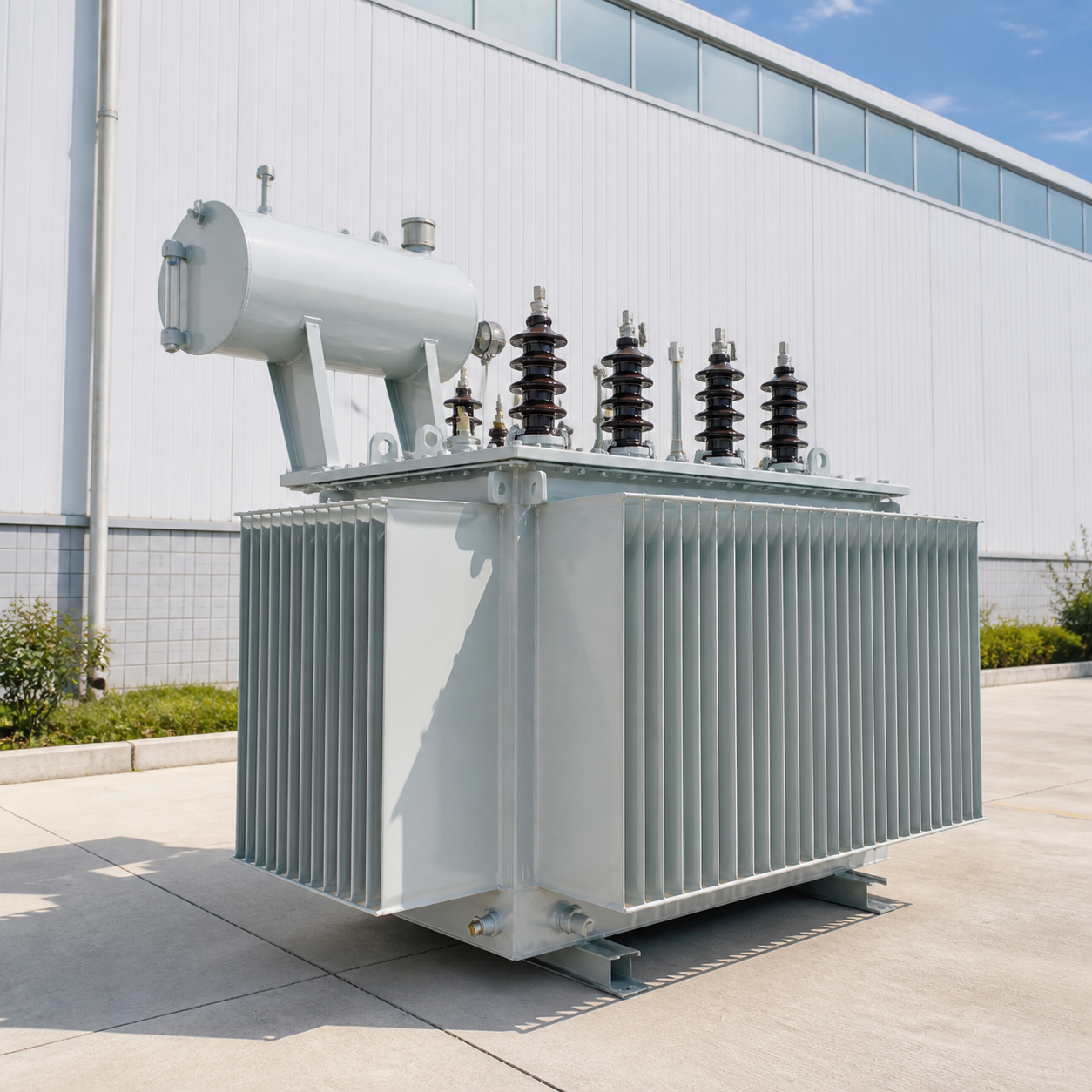
Corrugated Sealed Tank
The tank supports heat dissipation and oil-volume change, with pressure-relief provision subject to the order.
Construction scope boundary
Hermetically sealed transformer units aren't maintenance-free or automatically leak-proof. Peer-reviewed design work treats the sealed oil-immersed transformer as a multivariable problem involving electrical performance, grid harmonics and production constraints.5 That trade-off must be checked against the ordered design.
Patent context: A reviewed sealed-transformer patent record illustrates one implementation only; it is not proof of Talite model construction or performance.
Thermal path
- Heat generated by the windings and core moves through the oil and tank surfaces.
- Oil and tank surfaces support natural cooling and convection.
- The temperature-rise basis and cooling system must suit the application environment.
Dielectric path
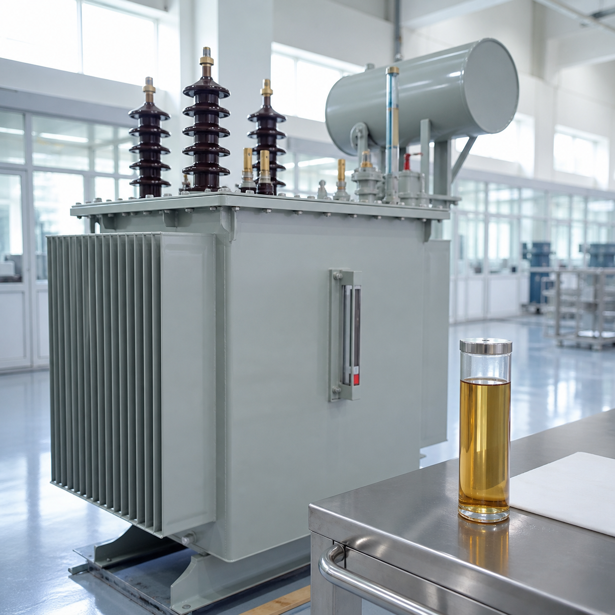
- Transformer oil supports cooling and electrical insulation.
- Moisture, contamination and oil condition affect dielectric strength.
- The fluid type, whether mineral oil or another approved liquid, requires confirmation.
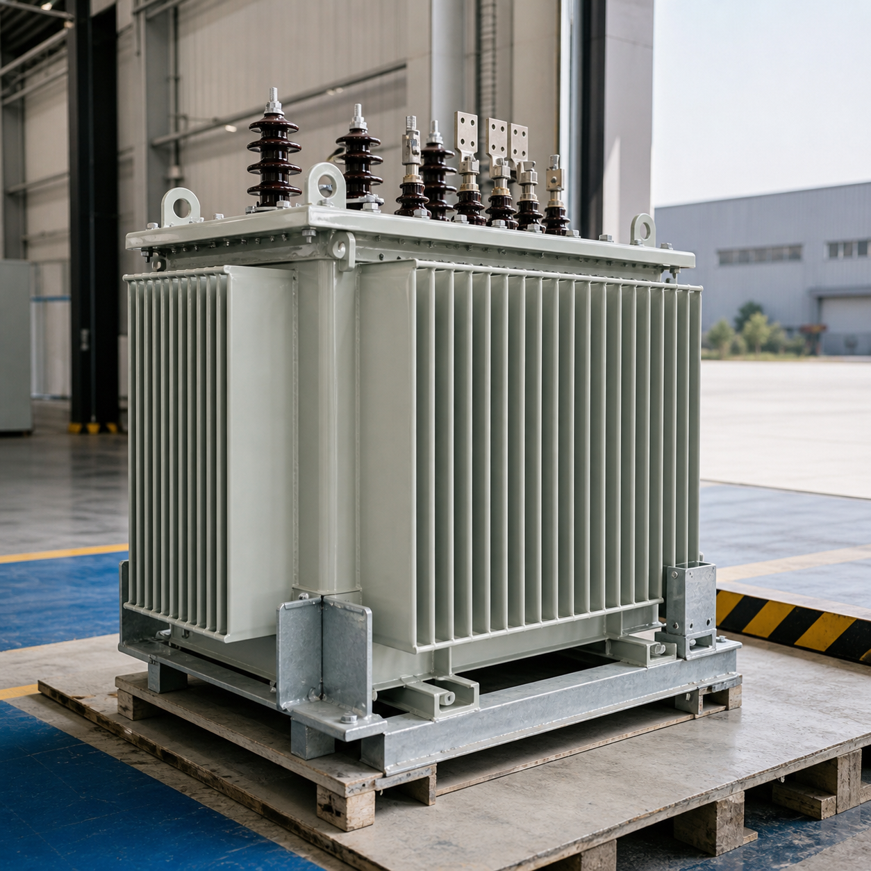
Mechanical path
- Corrugated enclosure geometry accommodates oil expansion within the design.
- The design must account for potential internal faults and resulting pressure.
- Transport, lifting, terminals and corrosion class remain project inputs.
- Sealing removes one external interface, but the design still must protect the internal assembly and fluid boundary during vibration or impact.
Items Talite must confirm before proposal approval
- Insulating fluid, temperature-rise basis, sound level and heat-dissipation requirement.
- Confirm whether the selected model uses copper or aluminum conductors.
- Pressure-relief, oil-level, thermometer, radiator, conservator or sealed-tank arrangement.
- Terminal, cable, coating, anti-corrosion, transport and installation constraints.
Configure Electrical Inputs, Site Conditions and Accessories
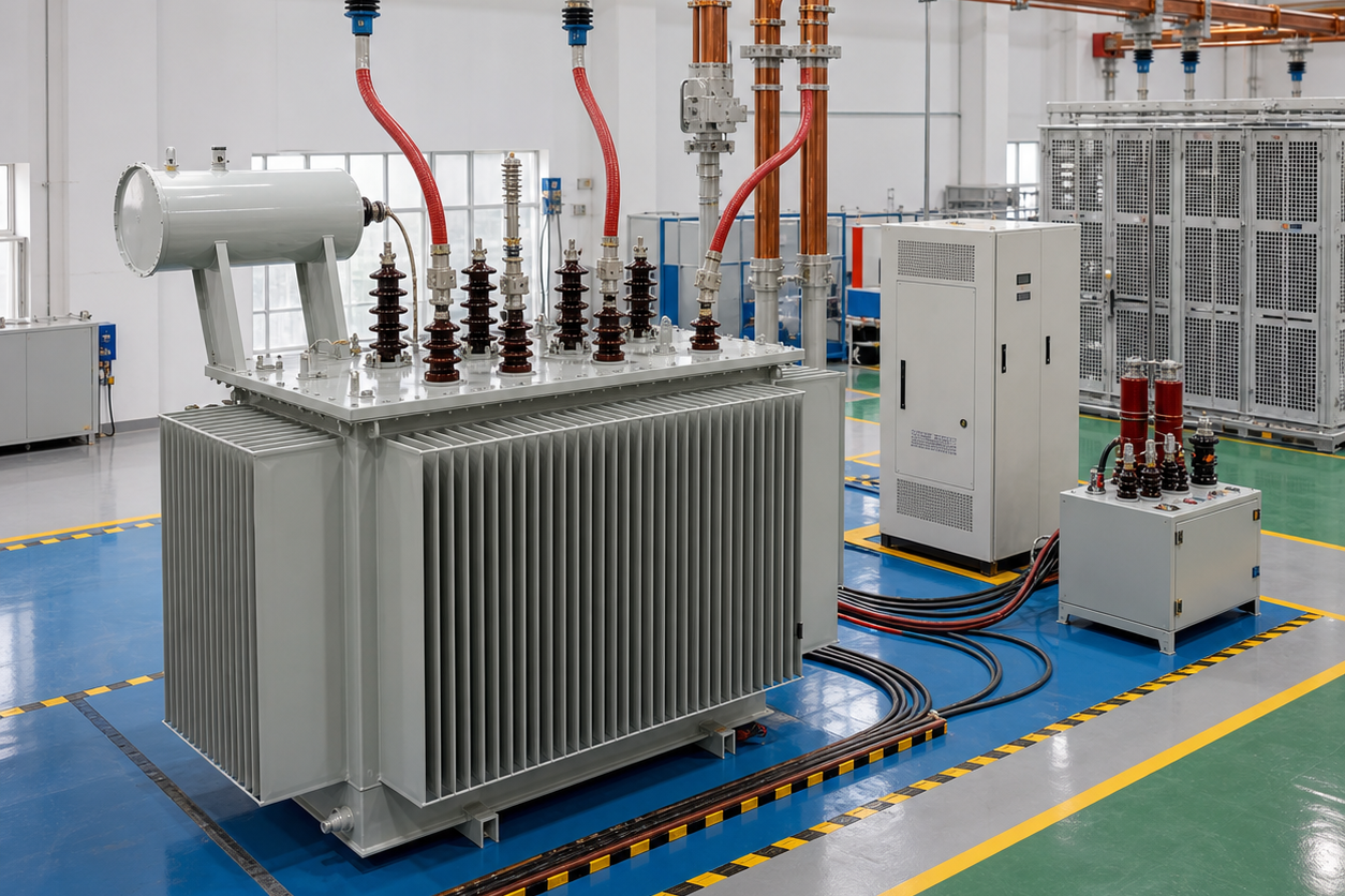
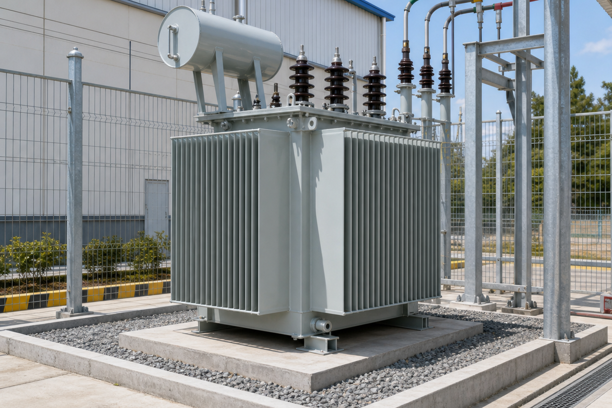
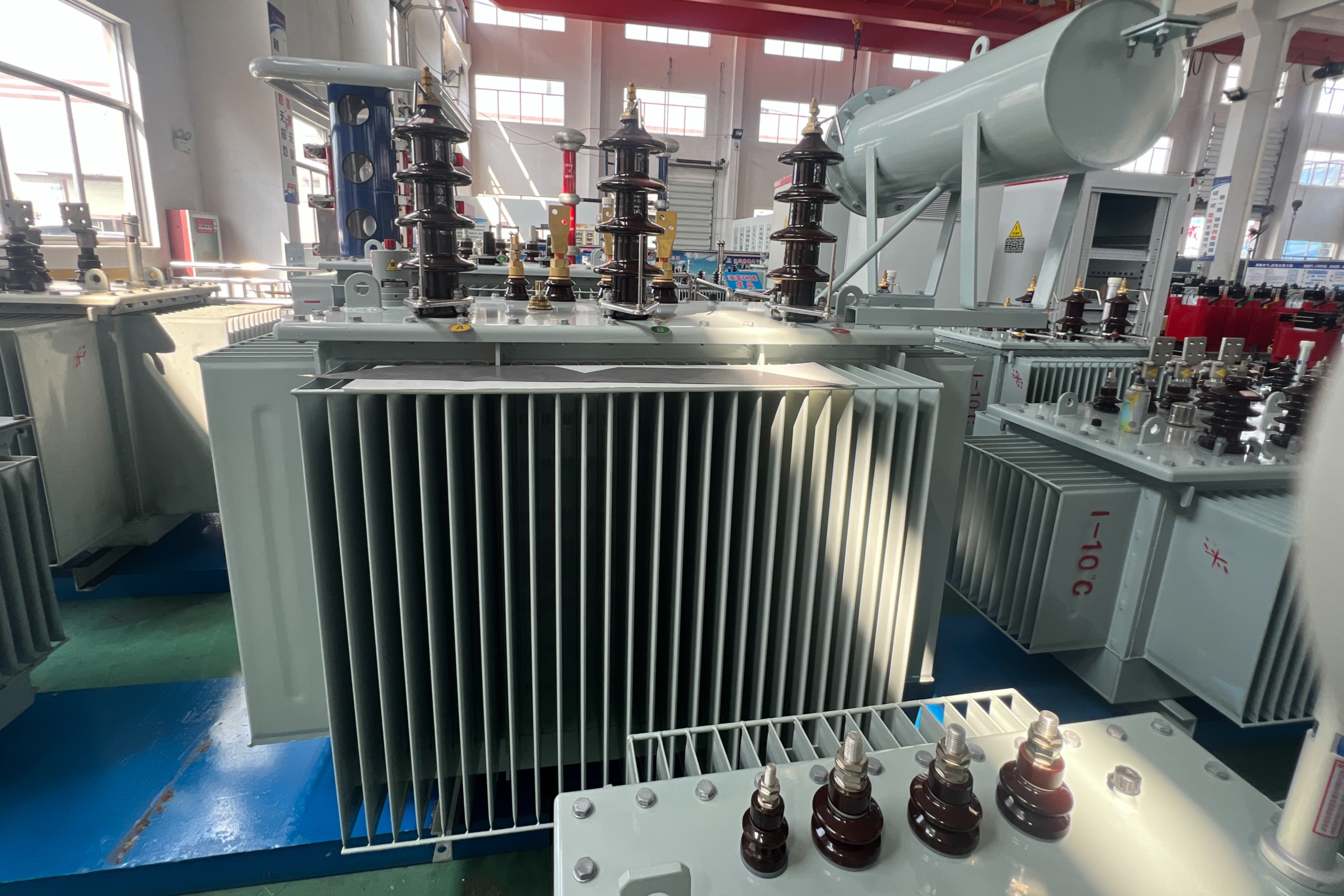
- Some U.S. workplace installations have special requirements for indoor vaults, combustible-material safeguards and containment.
- Access, enclosure, and hazard controls depend on installation and authority-with-jurisdiction requirements.
Talite-supplied normal-service data states an altitude limit of 1000 m and an ambient range from −25°C to +40°C. Conditions outside that range trigger an engineering review because an assumed derating factor can create reliability and approval risk.
- A sound electrical design can fail review when vault, cable, oil-containment or access interfaces are missing.
- Fire protection depends on the likelihood and consequence of oil-filled transformer operation, not on a universal answer.
- If the installation boundary shifts, a dry-type transformer, padmount or other architecture may be appropriate.
Translate broad search language into engineering inputs
Generic search phrases often collapse electrical duty, liquid system, application and evidence into one label. One common assumption is that the label already defines the required equipment, but the same phrase can describe very different duties. Use this terminology matrix to turn those phrases into RFQ questions without treating them as proof of model fit.
| Search language | RFQ translation |
|---|---|
| insulating oil; filled with insulating oil; submerged in insulating oil; tank filled | Name the required liquid, sealed-system arrangement, filling basis, containment boundary and service conditions. |
| oil transformers; type of transformer; power and distribution transformers | Define whether the duty belongs to a distribution unit, a larger power-transformer scope or another architecture before comparing schedules. |
| power systems; electrical distribution; power transmission and distribution | State the network role, primary and secondary voltages, frequency, grounding, protection interfaces and destination rules. |
| 5 MVA; power plants; power stations; solar power | Treat capacity and application words as screening inputs. A 5 MVA request or generation-site duty needs a separate engineered match rather than an assumed S11 or S13 schedule row. |
| working principle; oil circulates; types of oil; oil spill | Ask for the thermal path, liquid specification, tank arrangement, pressure provision, leak controls and site containment plan. |
| efficient power; efficient power transmission; transformer performance | Replace broad efficiency language with comparable no-load loss, load loss, impedance, temperature-rise and test-basis data. |
| right transformer; best transformer | Replace subjective ranking with a documented fit decision covering duty, site, standards, evidence, interfaces and commercial scope. |
| power supply; reliable power; high reliability; long service life; long-term reliability | Define the load profile, redundancy boundary, inspection plan, maintainability, spares and acceptance records needed to support the reliability objective. |
Evaluate Fit for Utility, Industrial and Renewable Projects
Utility distribution
- Inputs network voltage, load pattern, loss limits and utility specification
- Evidence model schedule, drawings, test scope and batch requirements
- Risk a different overhead or pad-mounted class may govern the project
Industrial facilities
- Inputs motors, harmonics, fault level, ambient and downtime consequence
- Evidence electrical schedule, accessories and acceptance criteria
- Risk nonlinear current can increase harmonic heating
Infrastructure and data centers
- Inputs footprint, sound levels, interfaces, redundancy and access
- Evidence outline drawing, cable arrangement and protection review
- Risk room, fire and continuity constraints can change the transformer type
Renewable energy and wind farms
- Inputs inverter interface, voltage range, harmonics and generation profile
- Evidence grid study and agreed electrical/test scope
- Risk a sector label never proves power capacity or model fit
IEEE guidance separates harmonic application review from the general transformer catalogue. U.S. national-laboratory research also identifies load mix and harmonic estimates as important inputs for modern power distribution.1213 Talite engineers ask how the electrical energy behaves because capacity, harmonics and thermal duty can't be resolved by an industry label.
- Baseline equipment classes can establish capacity and voltage boundaries.
- Final configuration depends on the primary and secondary systems, short-circuit duty, local requirements and thermal loading.
- Route generation, power transmission or higher-power duties to a power-transformer review.
- For pole-mounted equipment, use the single-phase pole-mounted transformer review.
- Review oil-immersed and dry-type options when indoor space or fire rules dominate the selection.
- For supplier due diligence across product families, use the distribution transformer manufacturer evaluation guide.
- Select a prefabricated substation solution when integrating switchgear and lower-voltage distribution networks.
Verify Tests, Standards and the Approval Document Pack
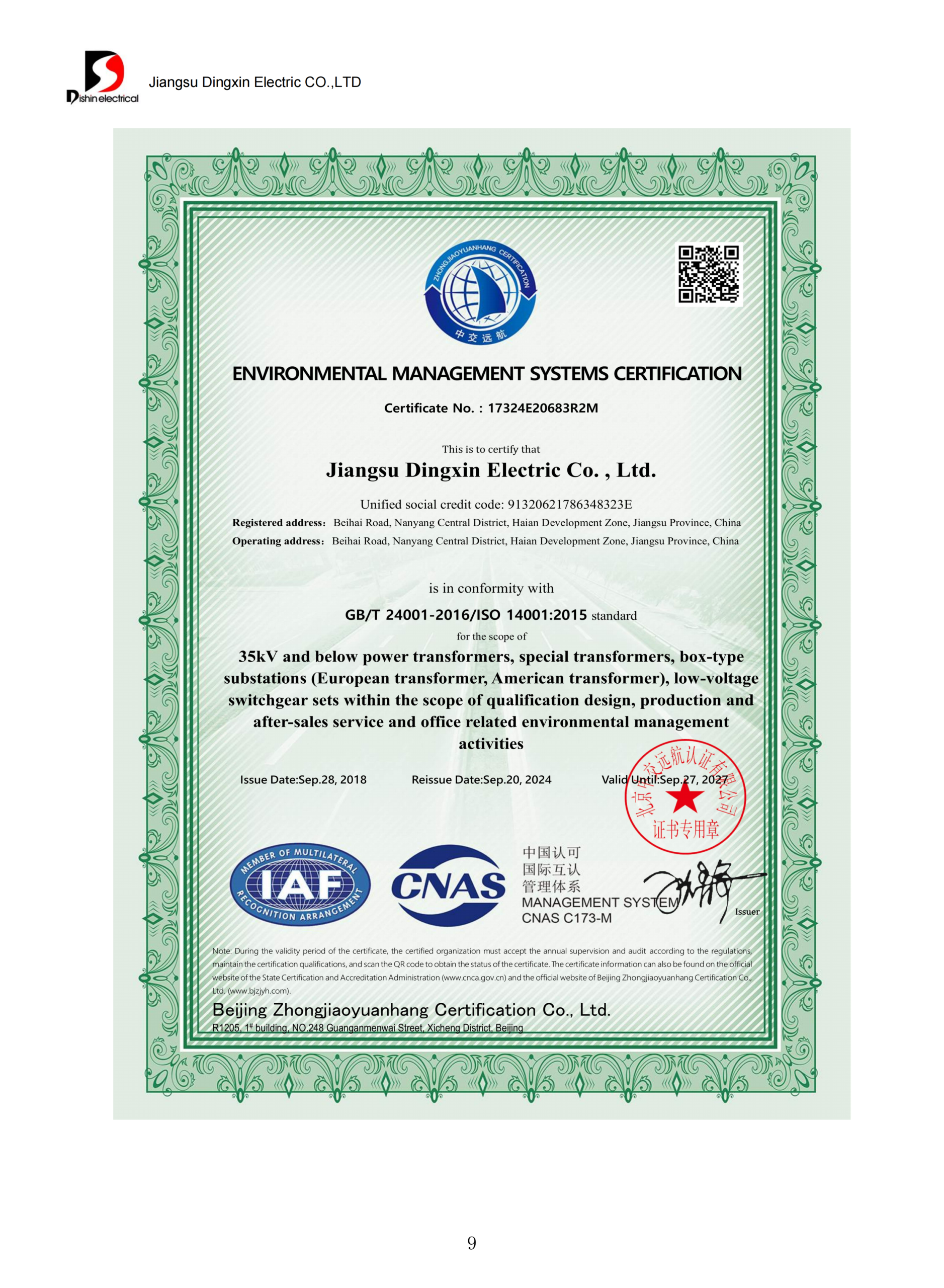
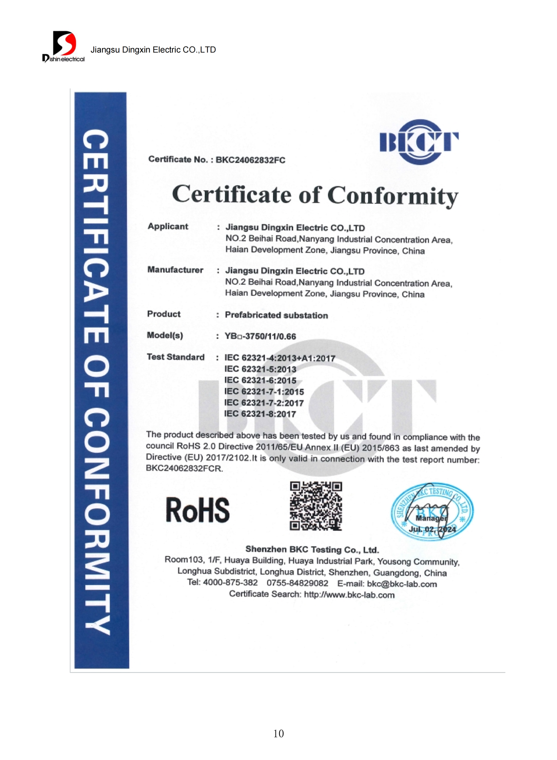
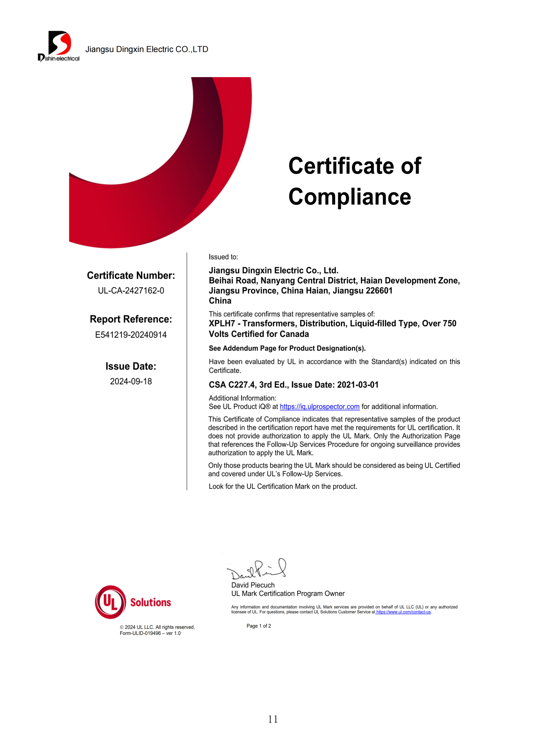
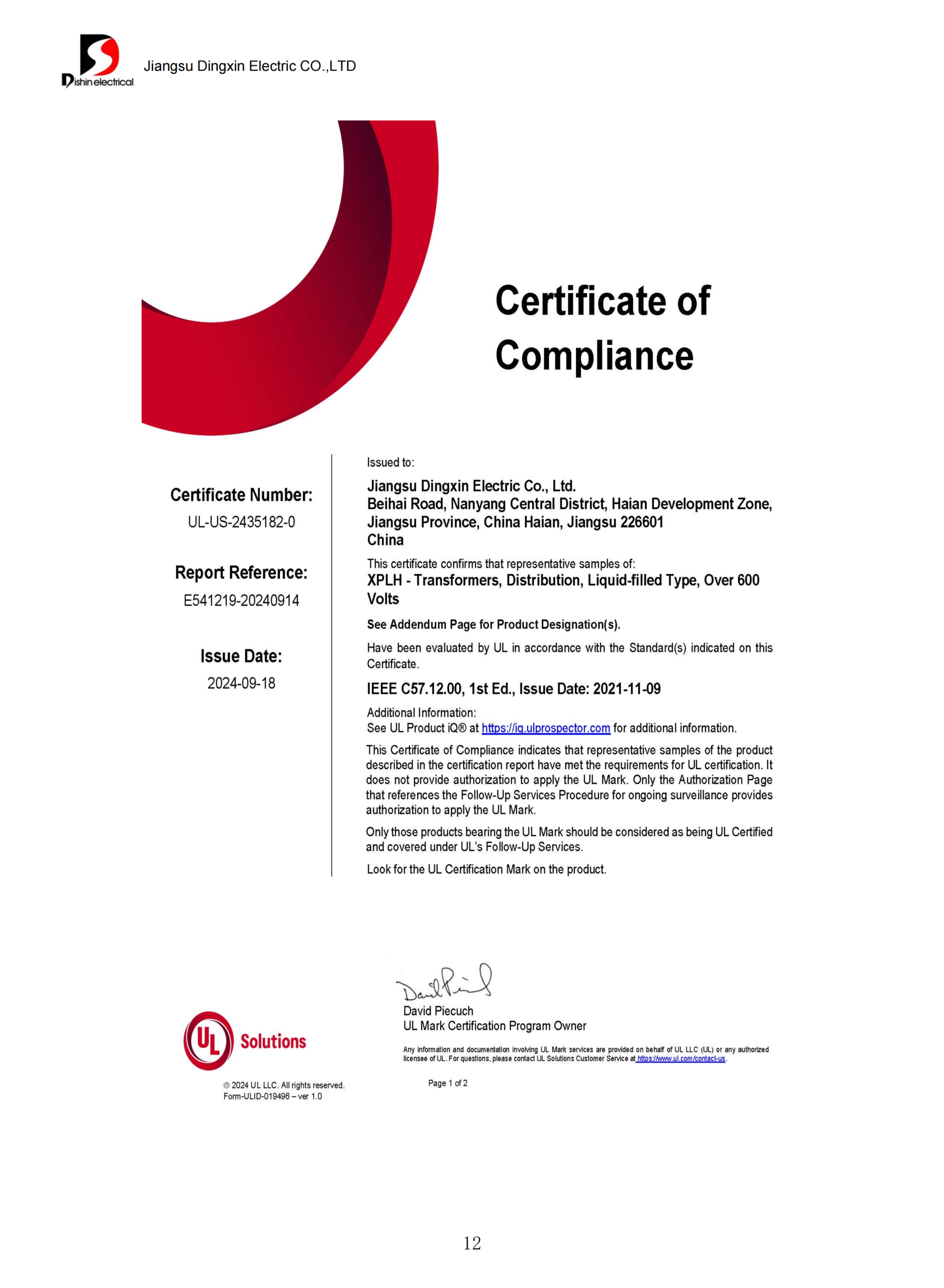
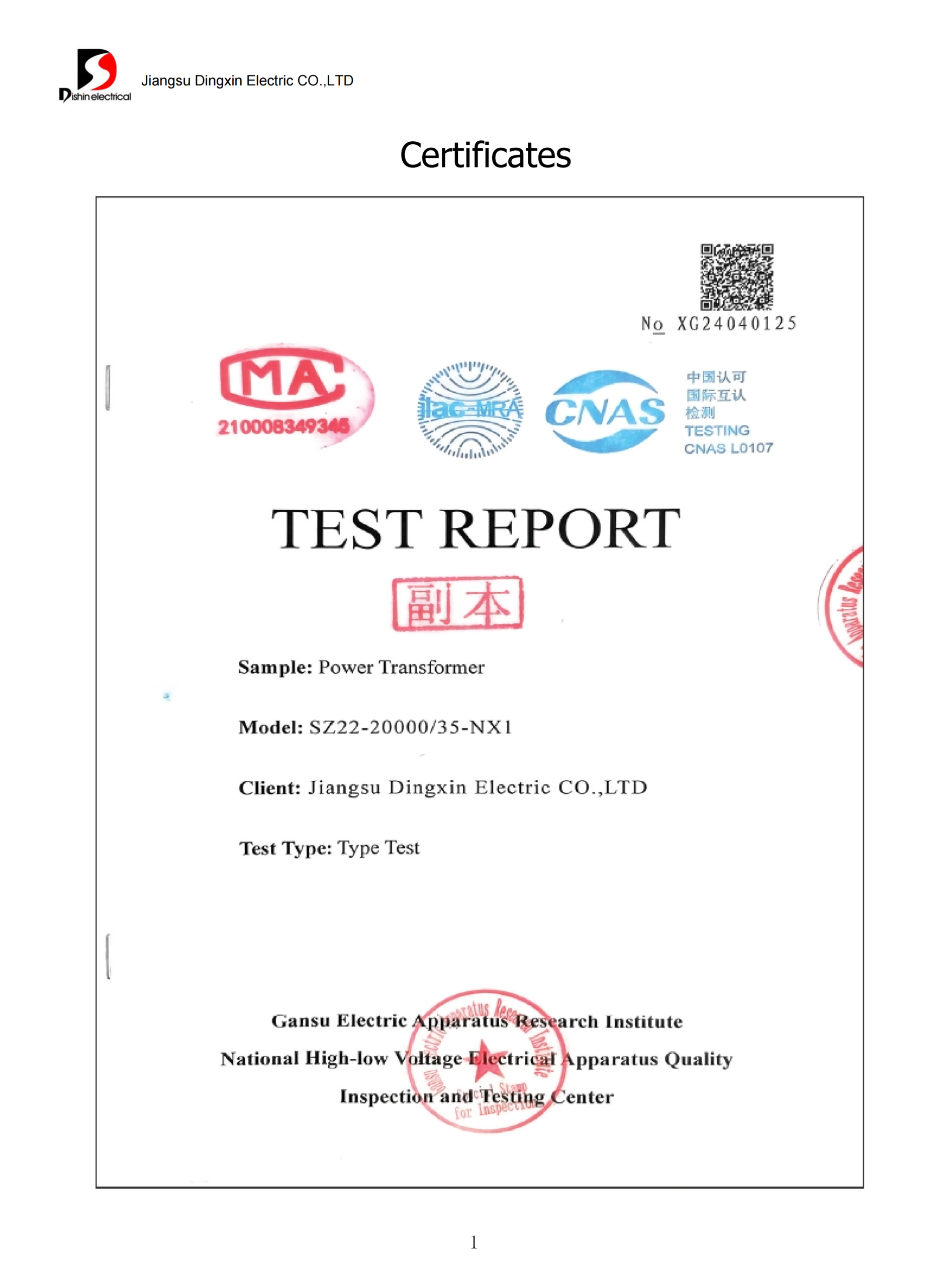
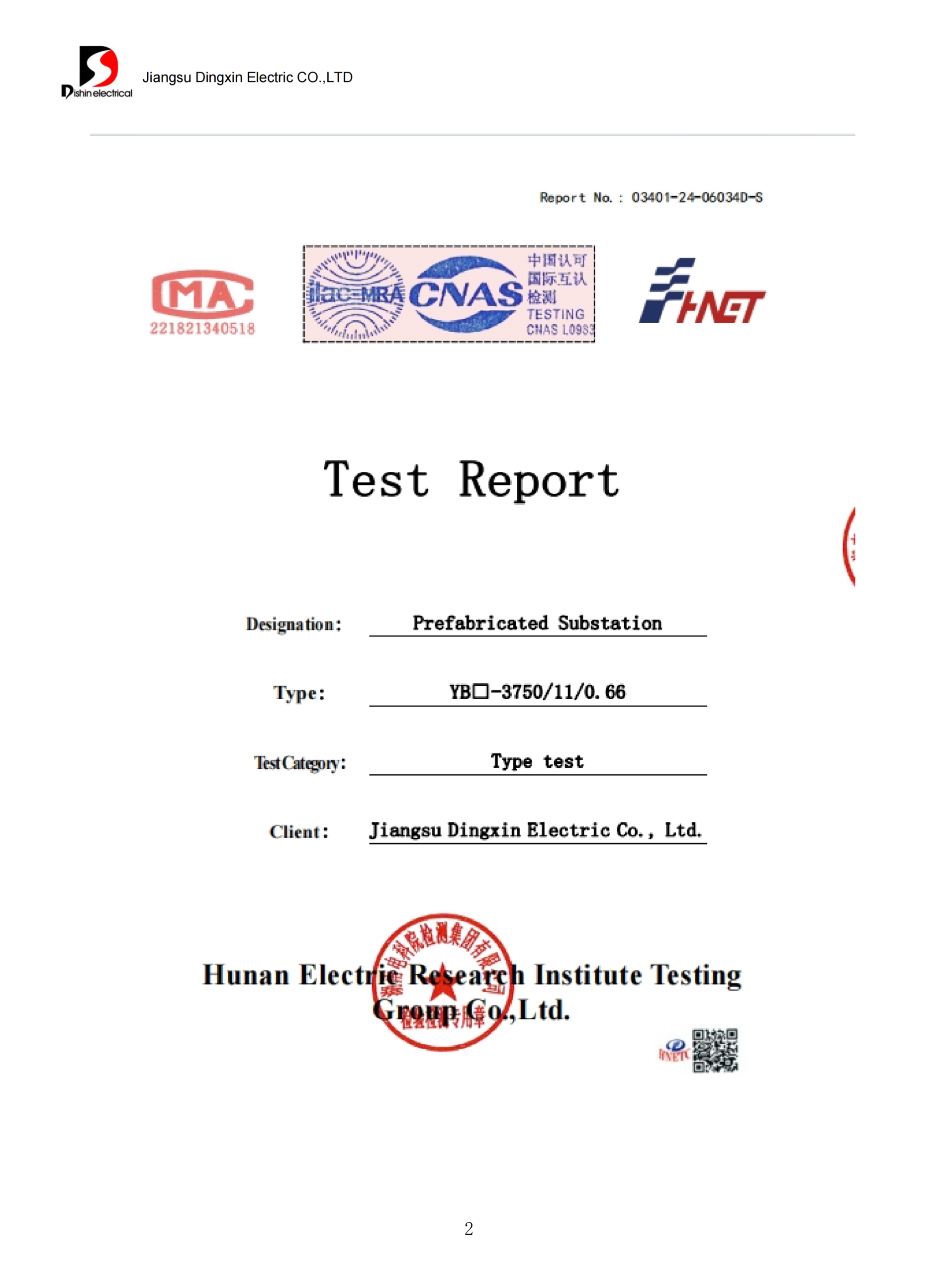
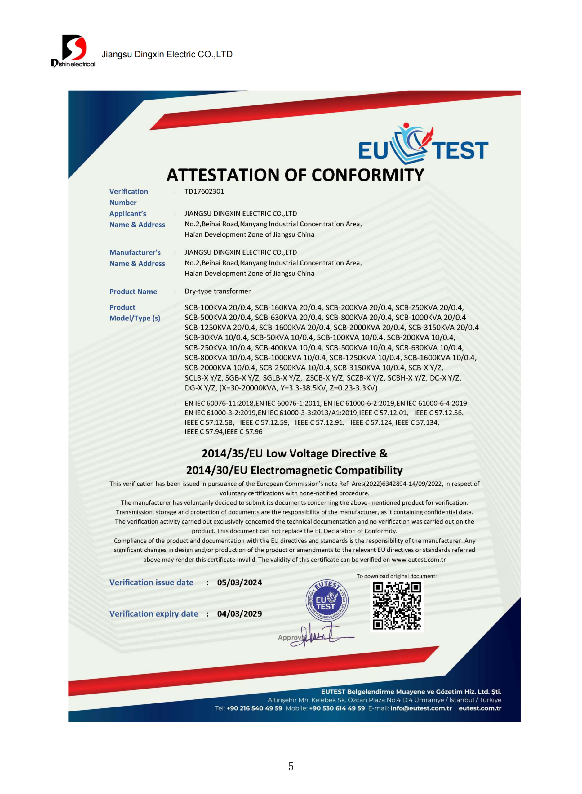
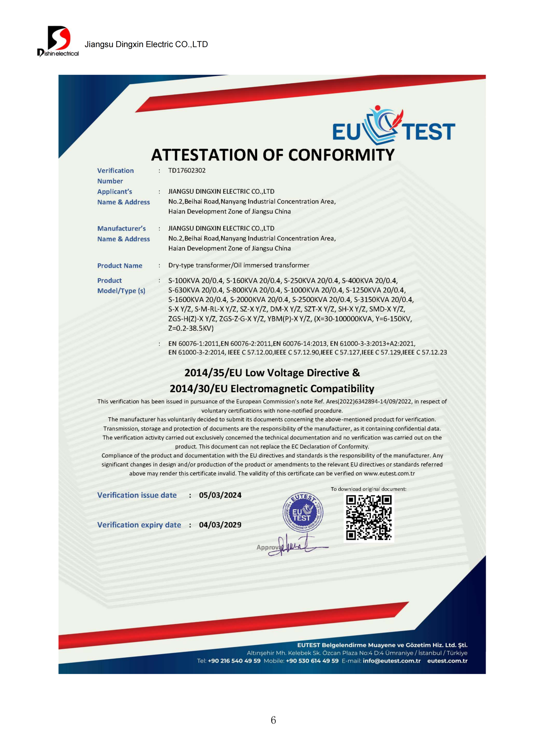
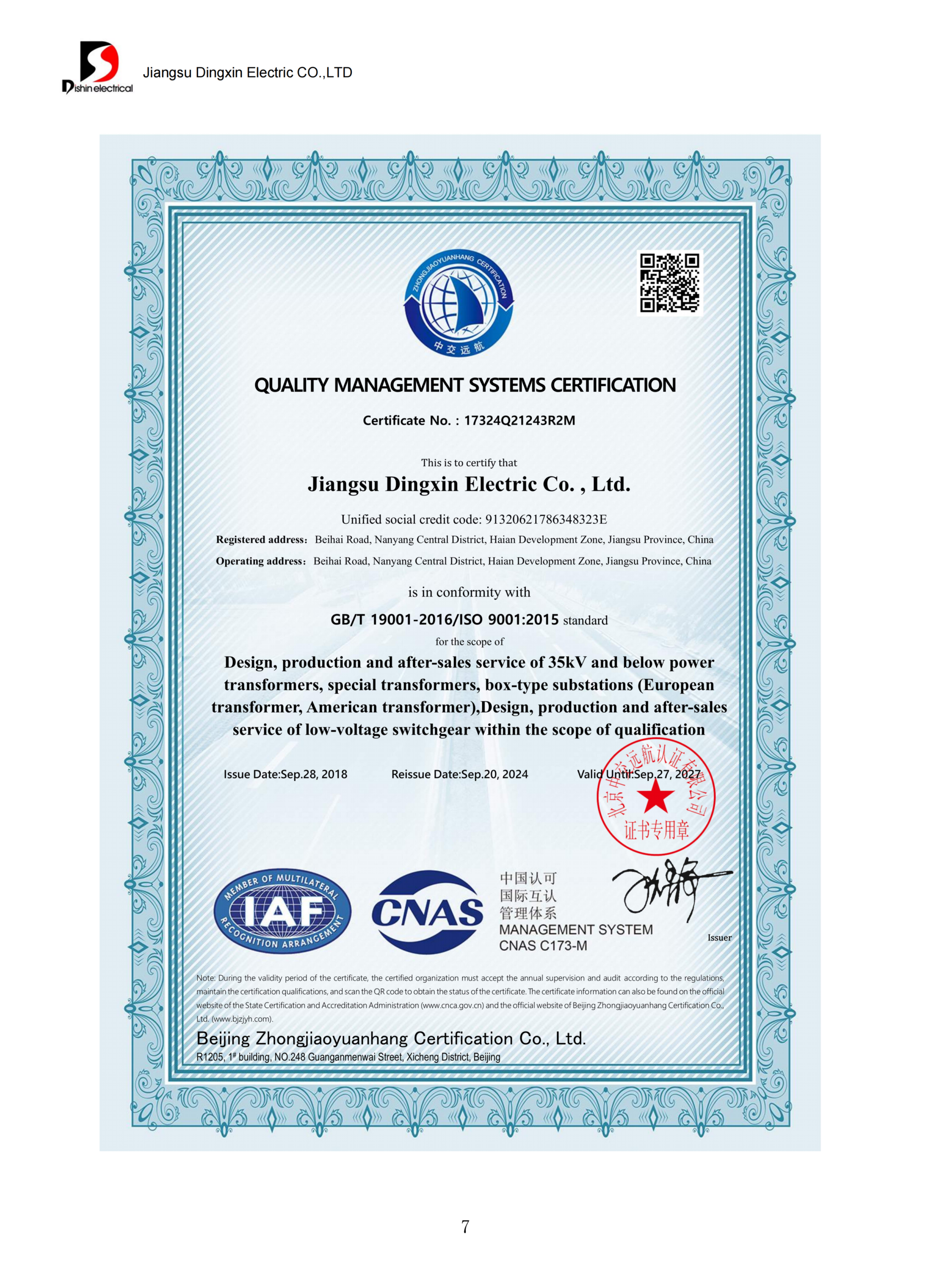
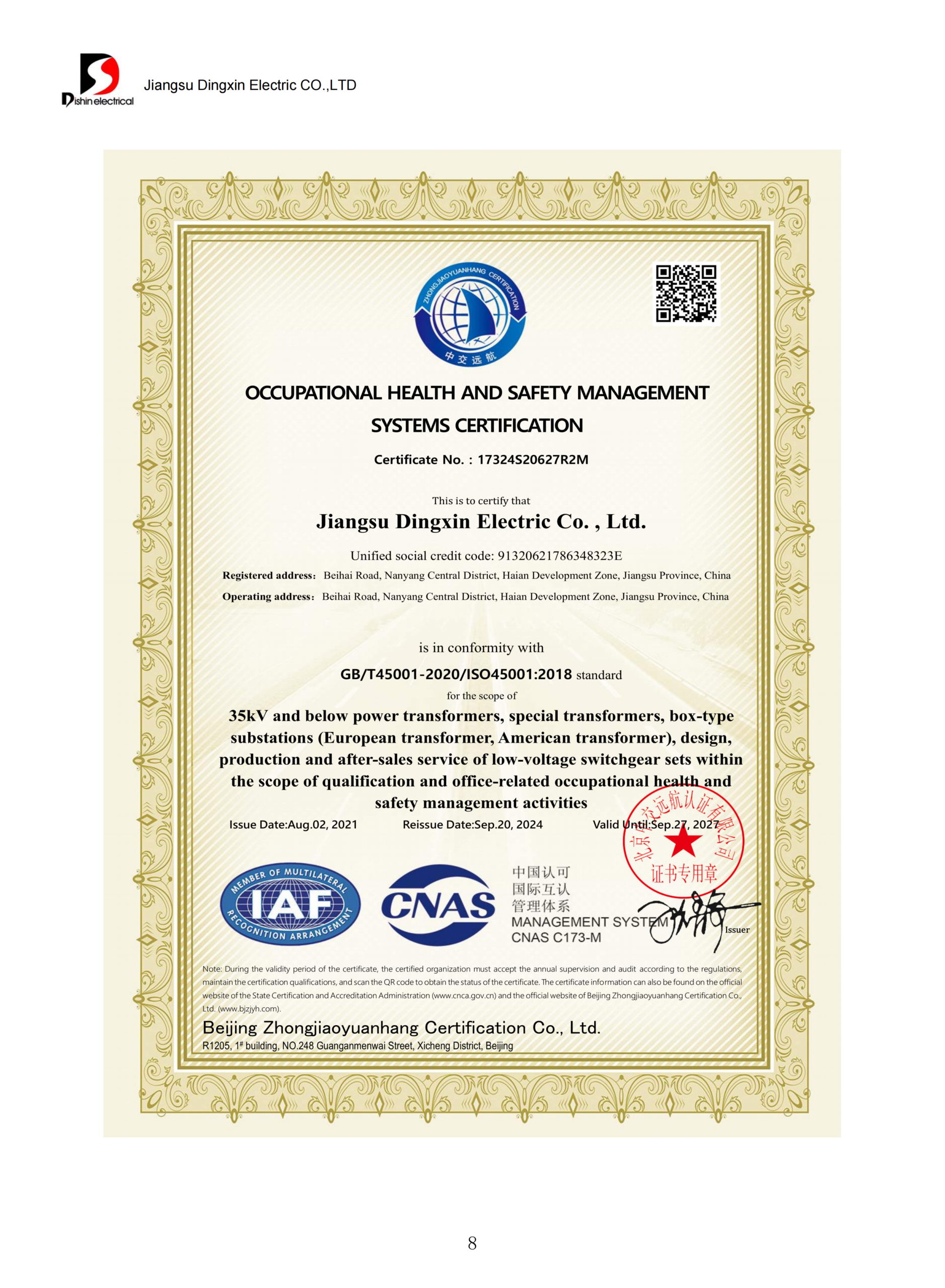
The evidence stream has three different tiers: statutory applicability, technical evidence for a specific product model, and organization-wide management certificates. Using one tier as proof of another creates a compliance gap and can delay purchasing even after the electrical design is finalized.
MODEL DATA
Available from supplied schedules; approve the ordered row.
TEST SCOPE
Confirm categories and deliverables for the proposed transformer.
MARKET RULE
Review product category, manufacture date and destination.
CERTIFICATE SCOPE
Not assumed from a logo, standard name or management system.
Design and guaranteed data
- Approved outline and nameplate drawings
- Model data sheet and guaranteed loss schedule
- Wiring and terminal diagram
- Accessory and spare-parts schedule
- Approved deviations, assumptions and exclusions
Inspection and handover
- Inspection and test plan
- Applicable routine test report
- Type or special-test evidence when required
- Packing list and shipping records
- Installation, operation and maintenance documents
Two evidence traps to avoid
- Listing in a public U.S. certification database doesn't constitute governmental product acceptance. The manufacturer remains ultimately responsible for submittal compliance.9
- Don't ask for the wrong proof format. An alternative efficiency method or kVA-group reporting may require a different compliance record in some U.S. cases.11
- IEEE C57.12.90 describes categories of tests including ratio, impedance, load loss, dielectric, temperature, sound, no-load loss, short-circuit and resistance. Talite must still review the standard, tests and records that apply to the order.10
| Proof area | Current page status | Required before approval |
|---|---|---|
| Model ratings and losses | Supplied user data | Approved project schedule |
| Routine test scope | Not asserted as a Talite universal package | Applicable plan and report |
| IEC / IEEE scope | Reference framework only | Current product and contract scope |
| CE / UL claims | Unverified for this series | Current certificate and covered model |
| U.S. efficiency status | Applicability not confirmed | Current category, determination and certification record |
| Management systems | Not used as product approval | Current certificate and legal-entity match |
Put evidence scope into the RFQ, not the final dispute
State the destination, standard, witness points and handover records before commercial alignment.
Engineering & Calculation Tools
FAQ: Oil-Immersed Distribution Transformer Questions
It's a distribution transformer whose core and winding assembly uses an insulating liquid for dielectric insulation and heat transfer. Project selection still depends on voltage, rated power, installation and destination requirements.
A liquid-filled transformer uses dielectric fluid, often mineral oil or another approved liquid. A dry-type transformer uses solid insulation and an air-cooling approach. Fire, environmental, enclosure, footprint and load requirements determine which design deserves engineering review.
Start with load profile, kVA, voltage, vector group, taps and impedance. Talite then checks the matching model row.
Use the same rating, voltage, reference condition and tolerance basis. Add the operating load profile and harmonic environment before using losses in a lifecycle comparison. If the quoted loss schedules use different assumptions, ask both suppliers to restate the basis before comparing lifecycle exposure.
Supplied normal-service conditions state altitude up to 1000 m and ambient temperature from −25°C to +40°C. Conditions outside that range require project review, not an assumed derating.
No. Fluid condition, bushings, protection, leakage risk and inspection scope remain service considerations.
Request the approved data sheet, drawings, inspection and test plan, applicable reports, accessory schedule and shipping documents. The exact routine, type or special-test scope must match the ordered design and contract. Add witness points and acceptance criteria to the RFQ if an owner, utility or third-party inspector must attend.
No. U.S. Department of Energy guidance says public listing isn't agency approval. The manufacturer remains responsible for valid certification submissions where the equipment is covered.
Electrical ratings, losses, impedance, design choices, accessories, testing, quantity, freight and trade terms affect scope. A quote based on kVA alone isn't a dependable comparison.
Talite can identify submitted items that match, differ or need confirmation. Final compliance and accessory scope must be documented in the approved proposal.
![Single Phase Pad Mounted Transformer Guide [2026]](https://toplit-transformer.com/wp-content/uploads/2026/08/single-phase-pad-mounted-transformer-guide-featured-1-150x150.png)