Get in touch with Talite Transformer Co., Ltd Company

Pole-Mounted vs Pad-Mounted Transformers: Which Fits the Project?


Pole mounted vs pad mounted transformer is a comparison of overhead-route equipment mounted on a utility pole and ground-level enclosed equipment serving an underground route. Selection starts with the planned feeder route; the utility, destination rules, and qualified project team control the arrangement.
| Decision category | Pole-mounted | Pad-mounted |
|---|---|---|
| Typical feeder route | Overhead conductors on utility poles | Underground primary cable |
| Equipment position | Elevated on a pole structure | At ground level on a prepared support |
| Primary interface | Overhead line, pole hardware, protective devices | Underground cable, terminations, radial or loop-feed interface |
| Civil scope | Pole, access, clearances, grounding | Trench, conduit, cable, pad, drainage, vehicle protection where required |
| Public interface | Elevated equipment with pole-line exposure | Locked enclosure in an accessible ground-level area |
| Service access | Pole-line crew and elevated-work method | Ground access, controlled working space, lifting path |
| Main siting screen | Pole route, vegetation, traffic, wind or flood exposure | Flood, drainage, traffic, public contact, working space |
| What the label cannot decide | Voltage, phase, kVA, protection, ownership, reliability target, installed scope, compliance, and lifetime cost | |
This table shows the key differences without turning them into a universal ranking. The quickest defensible answer is to eliminate the architecture that conflicts with the planned route, then compare the remaining site, electrical, operating, ownership, and commercial conditions on the same boundary.
Pole Mounted vs Pad Mounted Transformer: The Short Answer
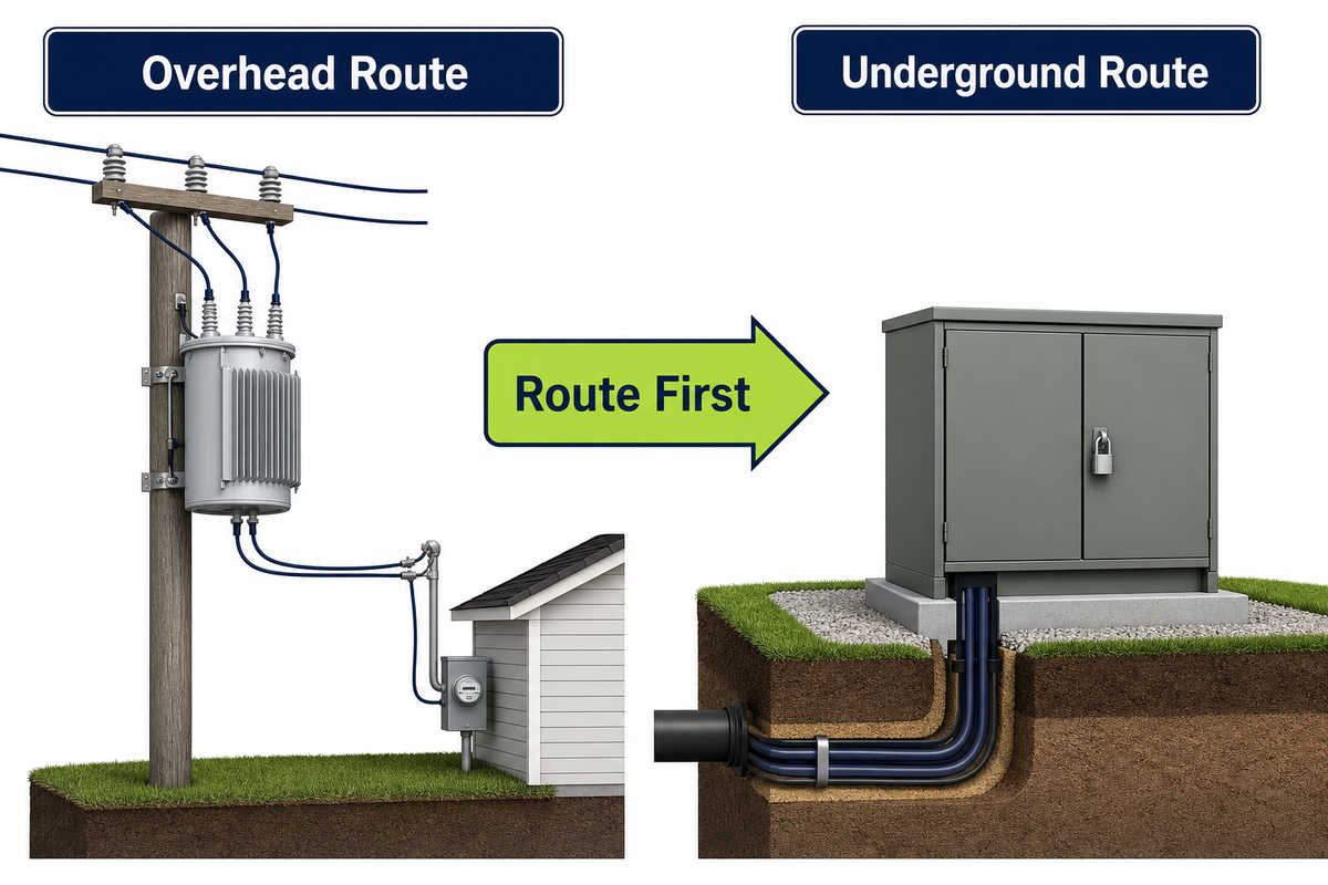
Choose the route before the cabinet: an overhead distribution route normally points toward a pole-mounted transformer, while an underground route normally points toward pad-mounted equipment. That answer only identifies the architecture to evaluate first; it does not approve a site, rating, protection scheme, or supplier offer.
Evidence Required for Common Comparison Claims
| Comparison phrases | Buyer evidence |
|---|---|
| “type of transformer,” “pad vs pole,” “pad mounted vs,” “pad-mounted vs,” “pad-mounted and pole-mounted transformer,” “difference between pad-mounted,” “differences between pad,” “key differences between pad-mounted” | Route, interface, site, ownership evidence. |
| “transformers are designed,” “transformers are ideal,” “transformers offer,” “pad-mounted transformers are ideal,” “pad mounted transformers offer,” “pad-mounted transformers are designed,” “transformers are best” | Duty, limits, standard, test, deviation. |
| “transformers are built,” “transformers are installed,” “transformers rely,” “transformer depends” | Component, owner, acceptance record. |
| “transformers usually,” “transformers are usually,” “transformers are typically,” “units are typically,” “typically used,” “pad mounted units often,” “pad units,” “pad-mounted transformers usually” | Destination utility or project rule. |
| “pole-mounted transformers are elevated,” “transformer is a ground-mounted,” “ideal for rural,” “nearby pole-mounted units,” “residential and commercial,” “transformers are ideal for residential,” “public areas” | Approved site plan. |
| “transmission lines,” “medium voltage,” “overhead power,” “overhead power lines,” “power distribution system,” “power distribution transformer,” “electrical equipment” | Voltage, feeder, equipment, owner. |
| “dry-type transformer,” “dry type transformer,” “transformer manufacturer” | Insulation and product-family evidence. |
| “reinforced concrete pad,” “copper or aluminum,” “ease of installation,” “influence transformer choice” | Drawings, materials, installed scope. |
| “choosing the right transformer,” “make an informed decision,” “utilities and developers,” “transformers play,” “safety are priorities,” “safe and efficient” | Owner, criteria, risks, review date. |
Route-First Elimination Path
- Mark the planned primary feeder as overhead, underground, or genuinely undecided.
- Remove any mounting architecture that conflicts with the serving utility’s accepted route.
- Test the surviving option against site, duty, protection, access, ownership, and cost.
What this cannot decide
- Whether the location is safe or permitted
- Whether radial or loop feed is required
- The correct phase, voltage, or kVA
- Which party owns civil and electrical scope
- Whether a named product complies
IEEE C57.12.20-2023 describes an overhead-type distribution-transformer scope, while the California Public Utilities Commission describes undergrounding as more than hiding a conductor: it can include trenches, conduit, vaults, underground conductors, and surface equipment such as pad-mounted transformers. These are useful power distribution and distribution network boundaries, but an IEEE catalog scope does not prove that a Talite product conforms, and a California program description is not a global construction rule.
Use the overhead-route product family only after an overhead route remains viable. If the route is underground, continue with site and interface questions before treating a pad-mounted unit as selected.
The First Filter: Overhead or Underground Feeder Architecture
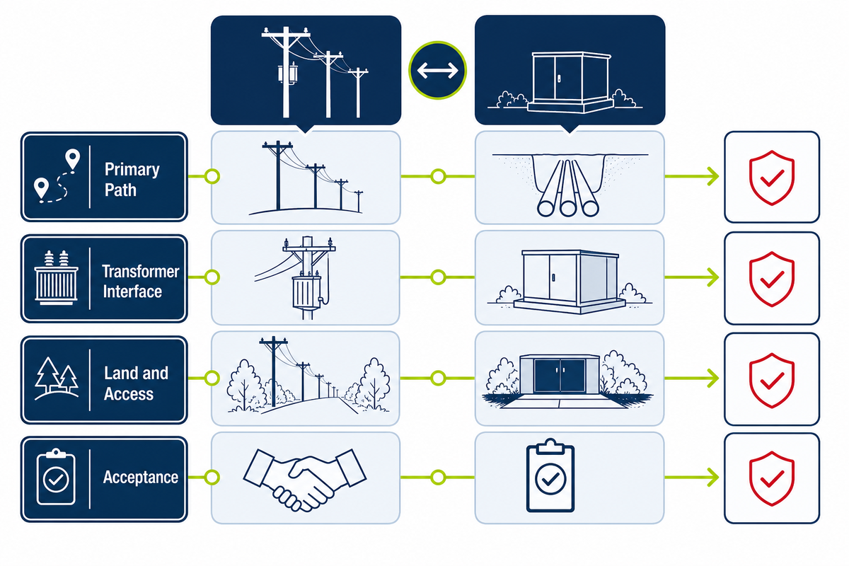
Feeder architecture is the first filter because changing from pole-mounted to pad-mounted equipment can change conductors or cable, terminations, protection, grounding, easements, civil work, access, and utility interfaces. Swapping the transformer enclosure alone does not convert the route.
| System boundary | Overhead route question | Underground route question |
|---|---|---|
| Primary path | Who supplies poles, conductors, insulators, and pole hardware? | Who supplies trench, conduit, cable, joints, and markers? |
| Transformer interface | What fuses, arresters, cutouts, grounding, and secondary leads are required? | What cable entrances, connectors, radial or loop feed, switching, and grounding are required? |
| Land and access | What pole location, easement, vegetation, and truck access are permitted? | What pad, working space, drainage, vehicle control, and lifting path are permitted? |
| Acceptance | Who reviews pole-line drawings and energization? | Who reviews civil, cable, enclosure, and energization records? |
The USDA Rural Utilities Service planning framework is a useful corrective to route-only thinking. It treats voltage, thermal loading, reliability, feasible alternatives, and economics as separate electrical distribution study inputs, so “overhead” or “underground” is an early elimination choice rather than the complete system design.
Why do some places have pad-mounted transformers instead of pole-mounted units?
Pad-mounted transformers commonly appear where the primary distribution route is underground, including sites where planners want to reduce exposure to selected overhead hazards or avoid an overhead streetscape. That choice also brings underground cable, civil work, ground-level access, and fault-location questions; it is not simply an aesthetic upgrade.
An existing underground route still does not prove that a particular pad location works. Flood elevation, drainage, public contact, vehicle paths, utility working space, cable topology, ownership, and local setbacks can disqualify it or force a different layout.
In suburban residential areas or commercial areas, a steel cabinet can enclose energized connections, but it cannot eliminate public-contact, vehicle, flood, or access risks. The project must also verify whether the utility requires a concrete pad, another prepared support, protective barriers, or a different location.
Decision rule
Use the route to decide what to study first. Use the full system boundary to decide what can actually be built, owned, operated, and quoted.
The route eliminates architectures that cannot connect to the planned feeder; the system boundary decides whether the surviving option can be built, operated, and bought.
The linked distribution transformer overview can help organize the equipment conversation, but the serving utility’s route and interface requirements remain upstream inputs.
Siting, Safety, Access, Flood, and Traffic Exposure
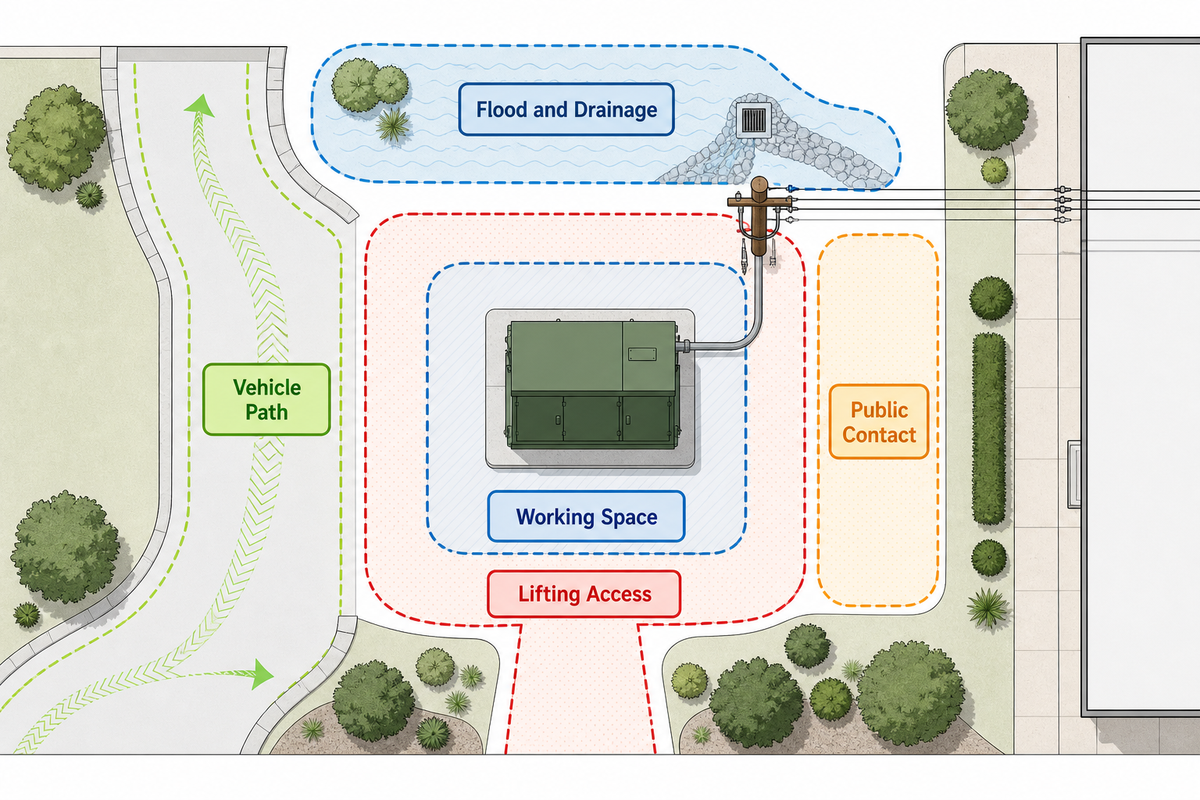
Screen the site before requesting price. Public contact, qualified-worker exposure, authorized access, working space, flood and drainage conditions, vehicle paths, vegetation, wildlife, lifting access, and insulating-fluid duties can eliminate or qualify either mounting option.
Do
- Obtain the serving utility’s current siting drawing.
- Separate equipment clearances from building or property setbacks.
- Map flood level, drainage, traffic, lifting, and emergency access.
- Confirm who controls the work area and switching.
- Identify fluid type and environmental applicability.
Do not
- Copy a distance from another utility into the project.
- Treat a locked cabinet as permission for public placement.
- Assume ground-level reach makes energized work safer.
- Turn a mitigation example into a universal mandate.
- Infer new-equipment PCB status from a retrofit rule.
FEMA training material gives examples such as elevating pad-mounted equipment above a base flood elevation or using multi-pole support for overhead equipment. Those examples show what a mitigation review might consider; they are not universal design instructions, and the project flood authority and serving utility must establish the actual elevation, anchorage, and access basis.
How far should a transformer be from a house?
There is no single portable distance for every transformer, house, utility, voltage, fire strategy, or jurisdiction. Ask the serving utility and local authority for the current rule set, then distinguish electrical working clearances around the equipment from fire separation, building setback, easement, acoustic, landscaping, and property-boundary requirements.
A utility drawing may state service clearances for its own equipment, but those dimensions cannot automatically be used for another owner or destination. Record the document title, revision, responsible authority, and approved layout instead of placing one unsourced number in the request for quotation.
For United States facilities, environmental review is conditional. The EPA states that oil-filled equipment at or above 55 gallons can count toward an applicable facility’s spill-prevention threshold, while plan applicability also depends on location, total aboveground capacity, and discharge potential; this is a screening branch, not a statement that every transformer needs the same plan.
Worker exposure also needs its own boundary. An OSHA partnership best-practice document describes “lock-to-lock” glove and sleeve use for energized underground residential distribution pad-mounted work, illustrating that opening accessible equipment still requires electrical-contact controls; the employer’s qualified-work procedures and applicable rules control the actual method.
For a replacement project, identify insulating fluid, legacy records, and PCB status separately. The EPA’s United States registration rule concerns PCB transformers and does not establish anything about new Talite equipment.
Equipment Architecture: Enclosure, Feed Topology, and Protection
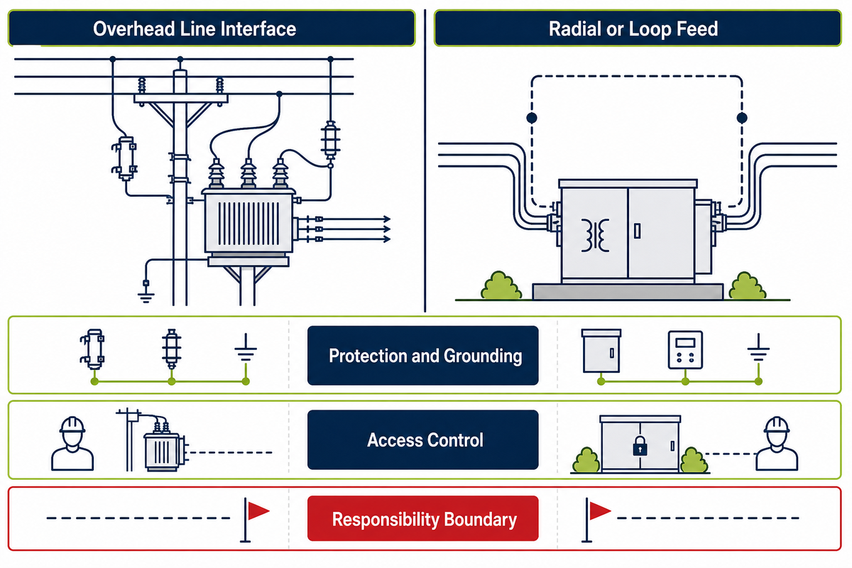
After the route is chosen, specify the equipment interface rather than stopping at “pole” or “pad.” The request must state enclosure and access scope, cable or line interface, feed topology, protection, grounding, terminals, and the party responsible for each external component.
| Specification question | Pole-mounted route | Pad-mounted route |
|---|---|---|
| Incoming interface | Overhead line, bushings, jumpers, pole hardware | Underground cable entrances, separable connectors or stated alternative |
| Feed arrangement | Line and tap arrangement defined by pole-line design | Radial or loop feed, with switching boundary stated |
| Protection | Fuses, cutouts, arresters, grounding, coordination owner | Fusing or protection, switching, arresters, grounding, coordination owner |
| Access and enclosure | Elevated access and pole-work method | Tamper-resistant enclosure scope, locks, compartment access, working space |
| External scope | Pole, hardware, conductors, secondary connections | Pad, cable, conduit, terminations, protective barriers where required |
IEEE C57.12.34-2022 addresses three-phase pad-mounted compartmental-type transformers with radial or loop feed, while IEEE C57.12.38-2025 addresses single-phase pad-mounted transformers in its stated scope. IEEE C57.12.28-2023 addresses enclosure integrity; these catalog pages help define interfaces and terminology, but they do not prove a supplier’s conformity, certification, or availability.
A procurement sheet should therefore name the governing edition, state whether compliance is required, list deviations, and request the exact supporting evidence. It must also identify the high-voltage and low-voltage winding interfaces, primary and secondary connection basis, and grounding boundary.
A pad-mounted distribution unit is not automatically a substation transformer, and a substation project may require a different equipment family and interface review. The ground-level cable-interface family page can frame product-family questions, but the project specification must own the final architecture.
Specification boundary
A mounting label identifies a physical arrangement. It does not replace a single-line diagram, cable or line interface, protection study, civil drawing, or evidence schedule.
Maintenance, Outage Isolation, and Replacement Access
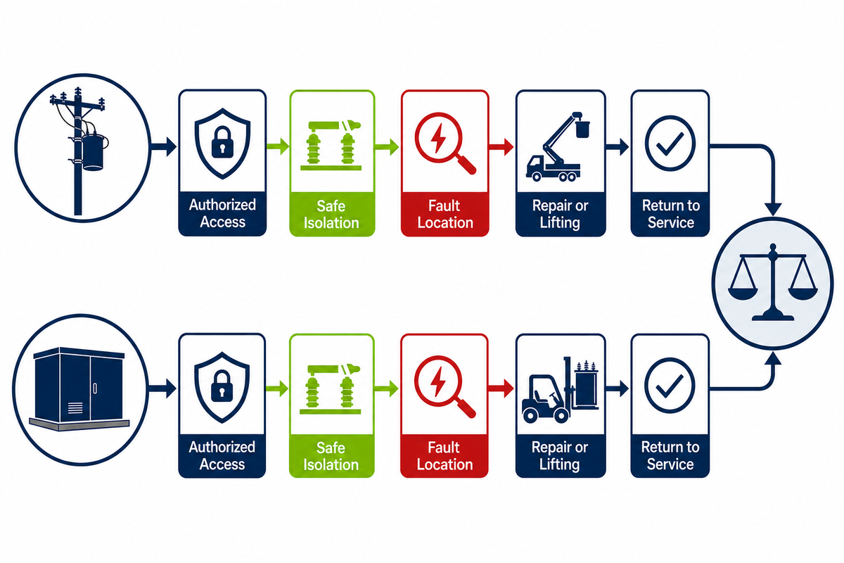
Neither arrangement is universally easier to inspect, isolate, restore, or replace. Compare the entire service path: authorized access, crew method, isolation points, fault location, lifting, traffic, vegetation, cable or conductor repair, spare strategy, and the time needed to return the route to service.
When the apparent maintenance winner loses
- Ground-level access loses when floodwater, vehicles, landscaping, public contact, locked-area control, or an unavailable lifting path blocks safe work.
- Elevated access loses when pole condition, traffic control, vegetation, weather, crew equipment, or replacement handling extends the outage.
- Underground protection loses when a fault is difficult to locate or damaged cable and joints take longer to expose and repair.
- Overhead visibility loses when wind, trees, wildfire, ice, or vehicle contact increases route exposure.
The California regulator notes a real tradeoff: undergrounding can reduce exposure to selected overhead hazards, yet underground faults may take longer to locate and restore. That is California program context, not proof that either route will deliver a specific reliability result at another site.
Inspection intervals also demonstrate why local ownership matters. Pennsylvania’s rule lists different maximum inspection cycles for overhead systems, above-ground pad-mounted equipment, and underground systems, but those intervals are Pennsylvania requirements—not a global maintenance schedule.
Easier physical reach is not the same as lower energized-work risk. The asset owner must define isolation, test-for-dead, grounding, switching authority, protective equipment, access control, and qualified-work procedures before maintainability can be scored.
Maintenance comparison unit
Measure the path from fault indication to safe isolation, access, repair or replacement, testing, and re-energization. “Technician reach height” is only one step.
Cost Comparison: Follow the Scope, Not the Transformer Price
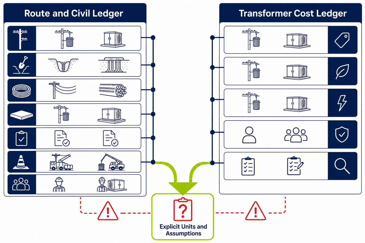
A fair cost comparison puts both alternatives on the same installed-system boundary. Keep route and civil scope separate from the transformer’s own total owning cost so a bare equipment price is never compared with a complete installed feeder.
Air-to-Earth Cost Shift
| Scope row | Likely owner | State what is included | State what is excluded | Uncertainty to close |
|---|---|---|---|---|
| Transformer | Supplier / buyer | Rating, accessories, tests, documents | External line, cable, civil scope | Approved duty and evidence |
| Overhead route | Utility / EPC / owner | Poles, conductors, hardware, grounding | Off-boundary upgrades | Pole class, span, easement, access |
| Underground route | Utility / civil / EPC / owner | Trench, conduit, cable, joints, pad | Unknown obstructions or remediation | Soil, crossings, drainage, restoration |
| Protection and connection | Utility / electrical contractor | Devices, settings, terminations, testing | Upstream or downstream changes | Fault duty and coordination |
| Permits and acceptance | Owner / EPC | Review, inspection, utility work | Fees not yet quoted | Authority, schedule, witness points |
| Future replacement | Asset owner | Access, lifting, outage, restoration | Unplanned network changes | Spare and replacement strategy |
Historical legislative research and current regulator material can show why overhead and underground cost categories differ, but they cannot supply today’s project price. Soil, route length, crossings, traffic control, existing utilities, outage constraints, permits, utility policy, and restoration standards can change the installed scope.
For the transformer itself, the longstanding USDA Rural Utilities Service total-owning-cost method evaluates bid price together with capitalized no-load and load losses over the stated study life. A cost-effective project comparison should record operating and maintenance assumptions separately and use the owner’s approved factors, reference conditions, horizon, and test evidence; if those inputs do not exist, report “not established” instead of inventing a payback or winner.
Two ledgers, one decision
Ledger 1 compares the whole feeder and civil route. Ledger 2 evaluates transformer purchase price and losses on the owner’s method. Combine them only after their boundaries, units, and assumptions are explicit.
Single-Phase, Three-Phase, kVA, and Application Fit
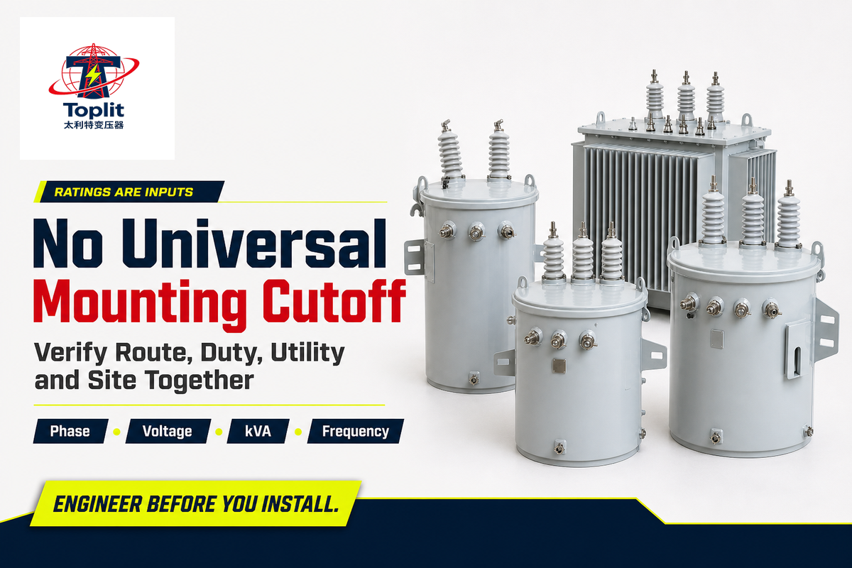
Phase, voltage, frequency, and kVA are specification inputs; none creates a universal pole-versus-pad cutoff. The route, serving utility practice, load duty, service arrangement, standard scope, and site still have to agree.
| Input | What it decides | What it does not decide alone |
|---|---|---|
| Phase | System and load connection basis | Feeder route or permissible location |
| Primary voltage | Insulation, interface, and utility compatibility | Complete equipment family or site approval |
| Secondary voltage | Utilization-system match | Pole or pad architecture |
| kVA and load basis | Thermal duty starting point | Universal mounting cutoff or overload policy |
| Frequency | Destination-system compatibility | Protection, access, or civil scope |
The DOE definition for covered United States distribution transformers uses electrical attributes and exclusions, while IEEE overhead and pad-mounted standards each have bounded scopes. These sources show why the full category must be checked; they do not create one global kVA threshold for mounting architecture.
For an overhead single-phase project, start the equipment conversation with the user-selected equipment page for an overhead single-phase service. For an underground single-phase route, compare the corresponding single-phase pad-mounted transformer interface, then verify both against project and utility requirements.
7-Check No-cutoff Rule
Do not ask “At what kVA must I switch to pad mount?” Ask “Which route and utility interface are permitted, and which product scope can meet the verified electrical duty?”
Use Eight Technical Inputs to Start Route Interface Evidence Pack
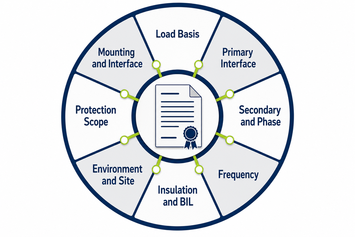
A comparable quotation needs more than the word “pole” or “pad.” Use these eight technical inputs as a non-exhaustive starting check, then attach route, ownership, destination, commercial, test, drawing, deviation, schedule, and acceptance requirements.
Route Interface Evidence Pack
| Starting input | Responsible role | Evidence to attach | Unresolved risk if blank |
|---|---|---|---|
| 1. Required kVA and load basis | Electrical designer / owner | Approved load schedule and duty cases | Wrong thermal duty or incomparable offers |
| 2. Primary voltage and system connection | Serving utility / engineer | Utility service data and single-line diagram | Incompatible insulation or interface |
| 3. Secondary voltage and phase | Electrical designer | Load and distribution design basis | Utilization mismatch |
| 4. Frequency | Owner / destination-market reviewer | Project electrical basis | Destination incompatibility |
| 5. Insulation and BIL basis | Utility / electrical engineer | Applicable standard and system study | Unverified dielectric duty |
| 6. Environment and site constraints | Civil, electrical, safety, owner | Site plan, ambient, altitude, flood, access data | Unbuildable or unsafe location |
| 7. Protection scope | Protection engineer / utility | Fault and coordination basis | Missing devices or incompatible coordination |
| 8. Mounting and interface | Utility / EPC / supplier | Route decision, drawings, cable or line details | Enclosure-only quote with system scope missing |
The checklist is incomplete. Add utility rules, importer duties, quantity, terms, tests, drawings, deviations, schedule, and witness points before comparing offers.
DOE reported that nationwide distribution-transformer lead times expanded from roughly 3–6 months in 2019 to 12–30 months in 2023 and described about 80,000 varieties. That historical United States supply-chain context explains why specification completeness matters; it is not a Talite lead time, stock, production-capacity, or delivery promise.
Talite Transformer Co., Ltd. has worked in the power-equipment sector for more than three decades and positions its team around transformer research, production, and international supply. Prepare the evidence pack, then request a project-specific transformer review.
For an underground route, the underground-route family page can inform discussion. Keep certification, tests, drawing approvals, commercial terms, and delivery evidence explicit rather than inferred from a product-family page.
Plan for Grid Hardening and Future Route Changes
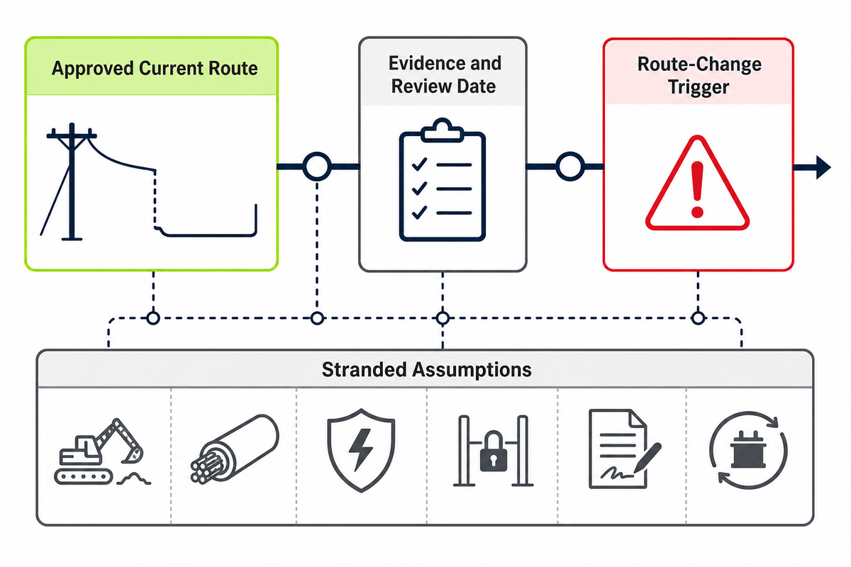
Future-proofing is a dated planning scenario, not a label attached to one mounting style. Record the expected network state, route owner, load-growth assumption, supporting evidence, review date, and the assets that would be stranded if the route changes.
| Decision-record field | What to write | Why it matters |
|---|---|---|
| Expected network state | Overhead, underground, mixed, or undecided at a stated date | Prevents a vague “future undergrounding” assumption |
| Decision owner | Utility, municipality, asset owner, or named project authority | Separates an approved plan from a preference |
| Evidence and review date | Program document, correspondence, drawing, and next review | Makes change visible before procurement |
| Stranded assumptions | Civil works, cable or conductors, protection, access, easement, spare strategy | Shows the consequence of a route change |
EIA reported that United States utility investment in both overhead and underground distribution infrastructure increased through 2023. That is system-investment context, not mounting market share, a demand forecast, or evidence that either architecture is universally more resilient.
DOE’s amended-standard compliance date for covered distribution transformers is April 23, 2029, but a June 2026 request for information asks about implementation effects on manufacturing, materials, supply, cost, and hardship. Treat this as an active United States policy process and a future verification checkpoint—not as a settled supply forecast or proof of Talite compliance.
Future-route rule
Do not buy for an undefined future. Buy against an approved current route, then document the evidence and trigger that would justify changing it.
Frequently Asked Questions
What is the main difference between a pole-mounted and pad-mounted transformer?
A pole-mounted transformer is elevated on a pole and normally interfaces with an overhead distribution route. A pad-mounted transformer sits in a locked ground-level enclosure and normally interfaces with underground cable. The mounting choice also changes civil work, access, protection, public interface, ownership, and service methods, so the feeder route is the first filter rather than the final design answer for a real project.
Why do some places have pad-mounted transformers instead of pole-mounted units?
Pad-mounted equipment commonly supports underground distribution where utilities or projects choose an underground route for planning, exposure, streetscape, or service reasons. The choice does not remove risk: it shifts work into trenching, cable, pad design, drainage, ground-level access, fault location, and restoration. Local utility, owner, safety, civil, and site rules decide whether the arrangement is feasible and who must approve it.
What is the purpose of a pole-mounted transformer?
A pole-mounted transformer changes the distribution-system voltage to the secondary service level required by the connected system while fitting an overhead feeder architecture. The complete installation also relies on pole-line hardware, protection, grounding, conductors, access, and utility rules. Its purpose is electrical transformation within that system boundary; the transformer still cannot be selected from its mounting label alone.
Are pad-mounted transformers still used?
Yes. Pad-mounted transformers remain part of underground distribution systems. Their use depends on the serving utility, site, electrical duty, cable topology, protection, enclosure requirements, ownership boundary, and current destination rules—not on a claim that underground construction has replaced overhead distribution.
What are common problems with padmount transformers?
Problems can arise when access is blocked by landscaping, fences, parked vehicles, or stored material; when drainage or flood exposure is ignored; when cable topology and terminations are incomplete; or when working space is not protected. Civil and electrical drawings may assign the same item to nobody or to two parties. Ground-level public contact and vehicle impact may also require controls. Underground faults can take longer to locate and repair in some systems, and an unavailable lifting path can delay replacement. These are planning and maintenance risks to screen, not proof that every pad-mounted installation will experience them.
Which transformer type is safest and easiest to maintain?
Neither type wins universally. Safety and maintainability depend on isolation, qualified work methods, public control, traffic, flood, vegetation, fault location, lifting, replacement access, and utility procedures. Compare the complete service path and the rules that apply at the actual site.
References and Sources
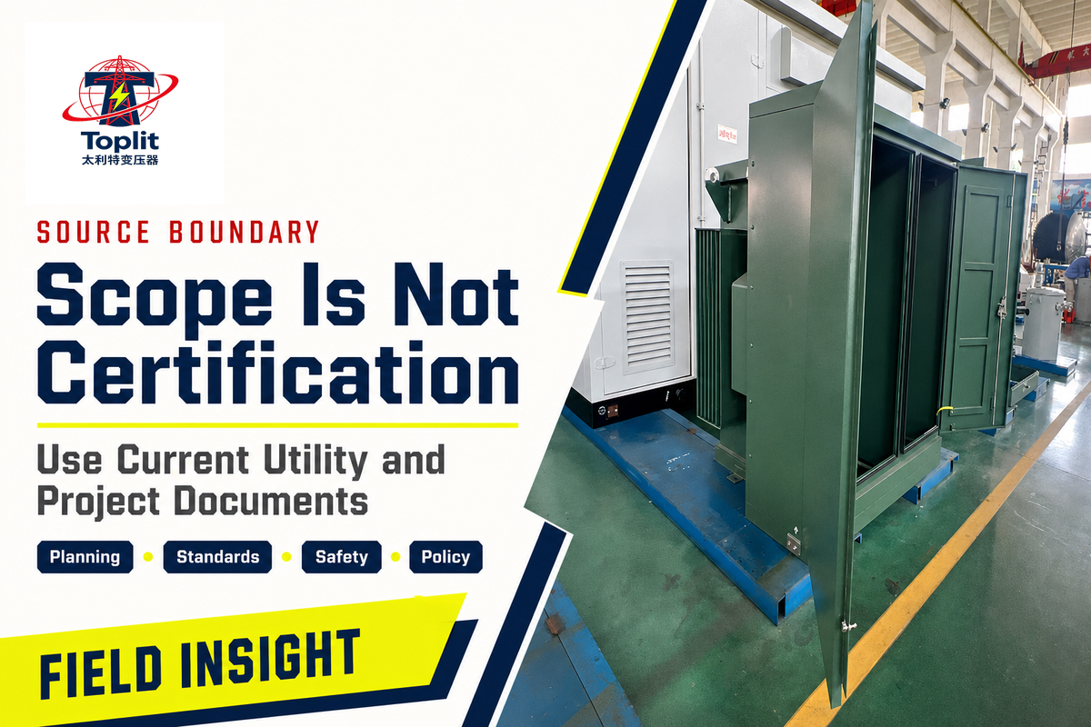
These sources establish public definitions, planning boundaries, standards scopes, and jurisdiction-specific examples. They do not certify a Talite product or replace the destination utility’s approved documents.
- USDA Rural Utilities Service — System Planning Guide
- USDA Rural Utilities Service — Transformer Loss Evaluation and Total Owning Cost
- California Public Utilities Commission — Undergrounding Program Description
- IEEE C57.12.20-2023 scope
- IEEE C57.12.34-2022 scope
- IEEE C57.12.38-2025 scope
- IEEE C57.12.28-2023 scope
- FEMA — Electrical Systems Mitigation Measures
- OSHA — General electrical requirements
- U.S. EPA — Oil-filled equipment and spill-prevention applicability
- U.S. Energy Information Administration — Distribution investment through 2023
- U.S. Department of Energy — Distribution Transformers
- U.S. Department of Energy — June 2026 request for information
Why we write this
About Toplit Engineering Insights
Toplit publishes transformer field guides from project routing, factory loss-data discipline, and specification review experience. We help engineering and procurement teams compare transformer types, voltage classes, installation constraints, and quotation evidence before they commit to a build.
- Oil-immersed, dry-type and pad-mounted transformer routes
- Loss data, rating schedules and factory evidence
- IEC / IEEE specification and site-input review
- Factory-direct transformer engineering support
Contact Profile
Talk with the Toplit Transformer Team
Company
Toplit Transformer Engineering Team
Toplit Transformer Engineering Team
Factory base
Hai'an, Nantong, Jiangsu, China
Hai'an, Nantong, Jiangsu, China
![Pad-Mounted Transformer: How It Works [2026 Guide]](https://toplit-transformer.com/wp-content/uploads/2026/08/pad-mounted-transformer-guide-featured-150x150.png)
![Single Phase Pad Mounted Transformer Guide [2026]](https://toplit-transformer.com/wp-content/uploads/2026/08/single-phase-pad-mounted-transformer-guide-featured-1-150x150.png)