Get in touch with Talite Transformer Co., Ltd Company

Pad Mounted Distribution Transformers vs Pole-Mounted Transformers

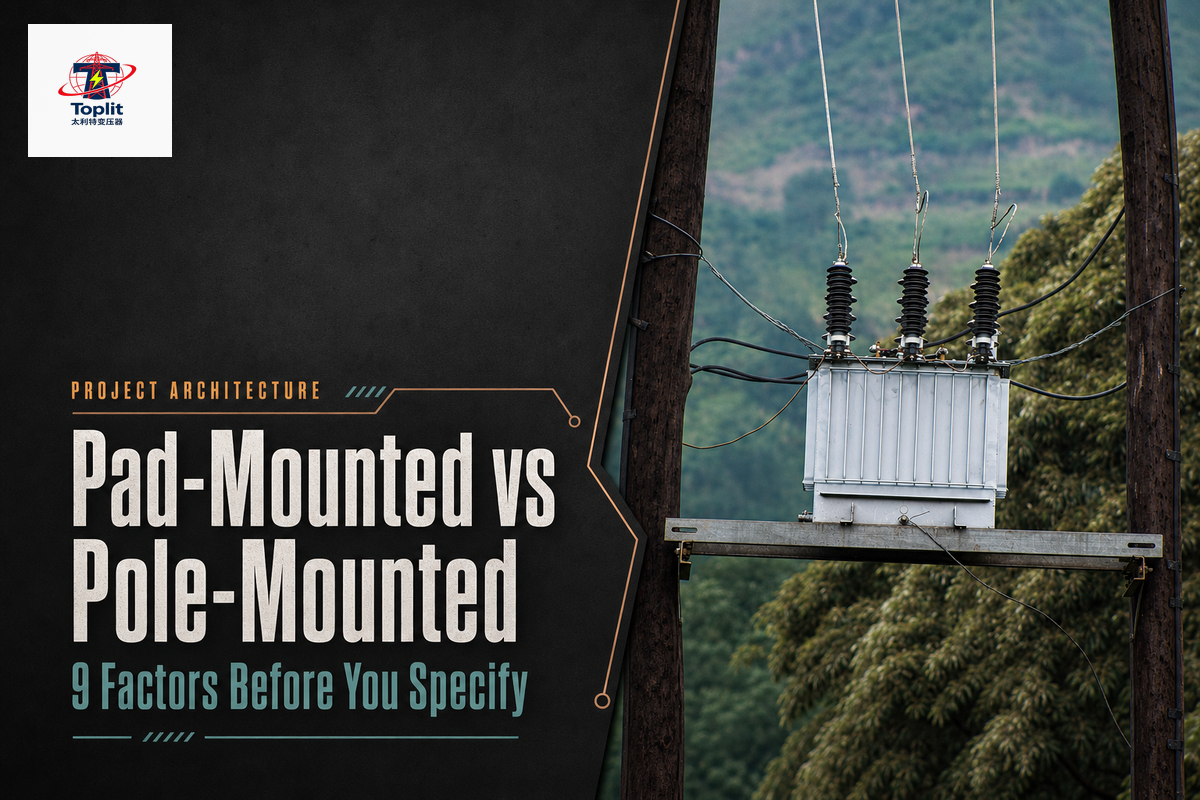
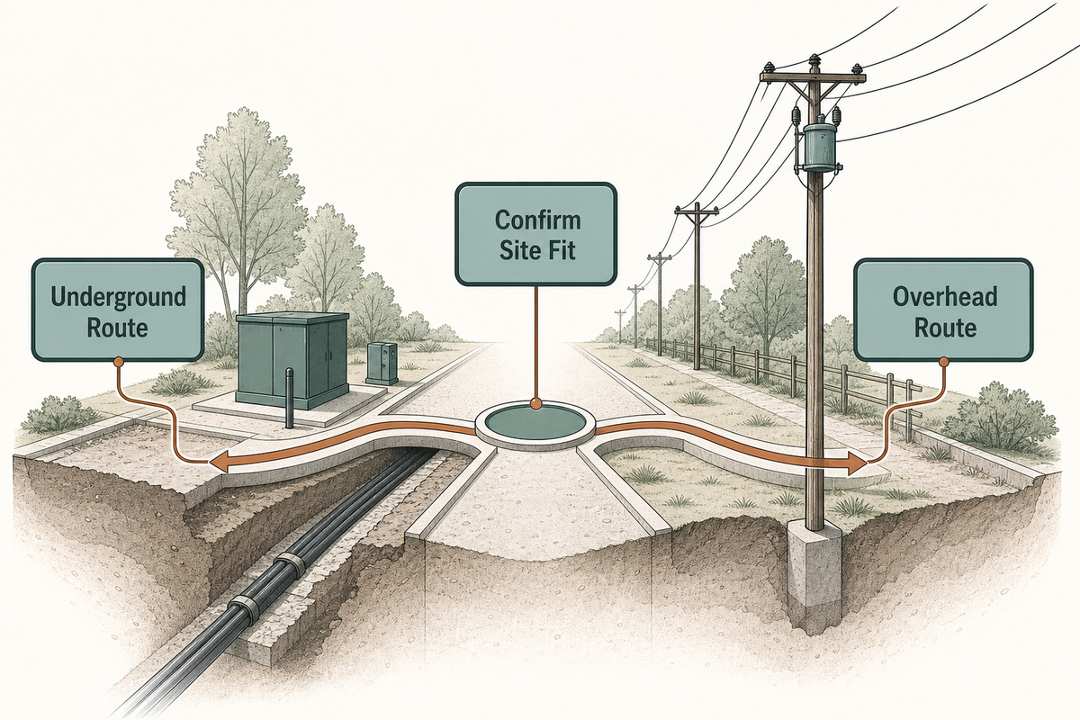
Pad mounted distribution transformers are usually the natural fit when a project uses underground primary distribution and needs a lockable, ground-level service point. Pole-mounted units usually fit an overhead network. The feeder route, public exposure, repair access, civil work, utility standards, and division of responsibility can still change the answer.
This comparison is for utility planners, EPC engineers, facility teams, and buyers deciding between two distribution architectures. It doesn’t replace an approved one-line diagram, utility standard, or site-specific engineering review.
Pad-Mounted or Pole-Mounted: The Short Answer
Choose the distribution architecture before you choose the transformer enclosure. A pad-mounted transformer is normally paired with underground primary and secondary cables. A pole-mounted transformer is normally integrated into overhead distribution lines and pole-top hardware. Neither arrangement is automatically better; each transfers cost, exposure, and maintenance work to a different part of the system.
| Project condition | Likely route to evaluate first | Who must confirm it |
|---|---|---|
| Existing underground distribution, public-facing site, or a low-profile streetscape requirement | Pad-mounted | Utility or EPC, civil designer, facility owner |
| Existing overhead feeder with acceptable pole and line access | Pole-mounted | Serving utility and line designer |
| Flood exposure, poor soil, traffic conflict, or restricted ground easement | Do not assume; perform a site-specific comparison | Civil, electrical, utility, and owner teams |
| Future feeder conversion or major load growth | Compare the future network, not only today’s transformer | Utility planning and owner capital team |
The relevant question isn’t “Which transformer is best?” It is “Which complete power delivery route can the project build, operate, isolate, and restore with the least unmanaged risk?”
Start With the Power Distribution Route, Not the Transformer Cabinet
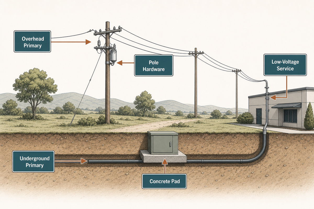
An overhead route carries the primary circuit on poles, then uses pole hardware, arresters, a fuse, bushings, and a pole-mounted distribution transformer to step the voltage down. An underground route moves the primary circuit through cable, conduit, or direct-buried construction to equipment mounted on a concrete pad. The pad-mount enclosure becomes the ground-level interface between the underground distribution network and the low-voltage service.
The USDA Rural Utilities Service publishes separate construction documents for overhead distribution assemblies and underground electric distribution. That separation illustrates the planning point: poles, pads, cable routes, grounding, protection, and access are system elements, not optional accessories added after a transformer price is selected.
The power path determines the mounting decision more often than the transformer name does. Whether a request says “pad mount transformer,” “pad-mounted transformer,” or “three-phase pad-mounted transformers,” the label does not settle the feeder route. Converting an overhead feed to underground distribution is a larger project than exchanging one electrical transformer for another.
Load type does not settle the mounting choice either. Single-phase neighborhood service, three-phase industrial environments, a data center, or a renewable energy interconnection can each sit within different power distribution systems. Engineers still need the actual voltage levels, network configuration, and utility interface.
Terminology can blur the scope. Padmount transformers are components in underground power distribution systems; they aren’t automatically equivalent to substation transformers. In urban infrastructure and commercial distribution, an underground power distribution route may preserve a low-profile streetscape, while the same power supply function can be served through overhead infrastructure elsewhere. Modern power systems, sustainable energy projects, and other modern power distribution systems still require this architecture-first check.
No mounting form guarantees safety and durability, ease of maintenance, quality and reliability, or a cost-effective result. Those outcomes come from coordinated power systems: correctly rated equipment, suitable protection, accessible switching, compatible interfaces, and a documented energy distribution and restoration plan. Treat a transformer as one part of the power distribution solution, not the whole solution.
Keep regulatory language in scope. The current U.S. definition in 10 CFR 431.192 covers equipment with input line voltage at 34.5 kV or less, output line voltage at 600 V or less, 60 Hz operation, and stated capacity bands of 10–5,000 kVA for liquid-immersed units and 15–5,000 kVA for dry-type units, subject to listed exclusions. It doesn’t prescribe pad-mounted or pole-mounted construction. DOE states that amended efficiency standards apply to covered equipment manufactured on or after April 23, 2029. These are equipment-scope and procurement-timing facts, not permission to bypass a utility’s mounting requirements.
Compare Distribution Transformer Site Footprint, Exposure, and Access
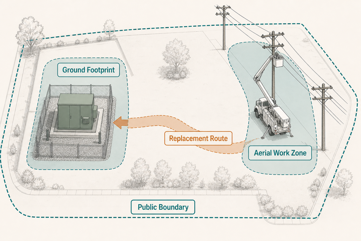
Pad-mounted electrical gear trades aerial space for a controlled ground footprint. The project needs a pad, cable path, drainage, working zone, and route for replacement equipment. Landscaping, parked vehicles, snow storage, walls, and later site changes can gradually eliminate that access.
Pole-mounted equipment may reduce the ground equipment footprint, but it requires a suitable pole line and aerial work zone. Pole condition, conductor clearances, road access, bucket-truck positioning, vegetation, and nearby utilities can all become constraints. Height may reduce casual public contact with the transformer, but it doesn’t remove line-work hazards or the need for qualified procedures.
Public contact and field access are distinct design challenges. A locked pad-mounted enclosure controls direct access to equipment, while bollards, grading, drainage, and landscaping address different site hazards. Pole placement raises equipment above normal contact height, while the line route and work method determine aerial exposure. A claim such as “pad-mounted is safer” or “pole-mounted is safer” overlooks these separate risk paths.
Don’t copy a clearance number from a generic article. Building separation, working space, fire considerations, vehicle protection, and utility access can be governed by different codes, utility standards, local rules, and approved drawings. Ask the serving utility and authority having jurisdiction to confirm the project-specific envelope.
Reliability Depends on the Whole Fault-and-Restoration Path
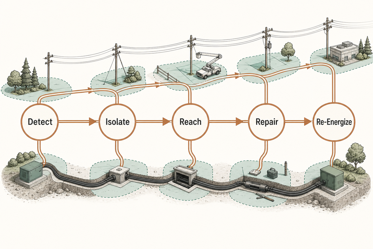
There is no universally more reliable mounting position. Weather events and electrical faults affect underground and overhead distribution systems differently, and crews locate and clear those faults through different procedures. A useful comparison follows the restoration path from detection through safe isolation, repair, and re-energization.
| Restoration step | Pad-mounted / underground route | Pole-mounted / overhead route |
|---|---|---|
| Locate the affected section | Confirm switching state, cable section, terminations, and accessible test points | Patrol visible line, pole hardware, protection, and conductor path |
| Isolate safely | Use the approved underground switching and grounding procedure | Use the approved line isolation and grounding procedure |
| Reach the equipment | Preserve ground route for crews, test equipment, and lifting | Preserve road and aerial access for line crews and lifting equipment |
| Repair the failed element | The failed element may be the transformer, connector, termination, or underground cable | The failed element may be the transformer, fuse, arrester, pole hardware, or overhead conductor |
| Reinstate the site | May include cable, pad, paving, drainage, or landscaping work | May include pole, conductor, hardware, vegetation, or traffic-control work |
Compare the fault-to-restoration path, not a single weather-resistance claim. Sectionalizing, spare strategy, accessible switching, protection coordination, tested interfaces, clear records, and realistic crew access can improve either architecture. Claims about uninterrupted power, efficient power delivery, or reliable power distribution must be tied to the complete system design and operating plan.
Compare Installation Scope, Not a Bare Transformer Price
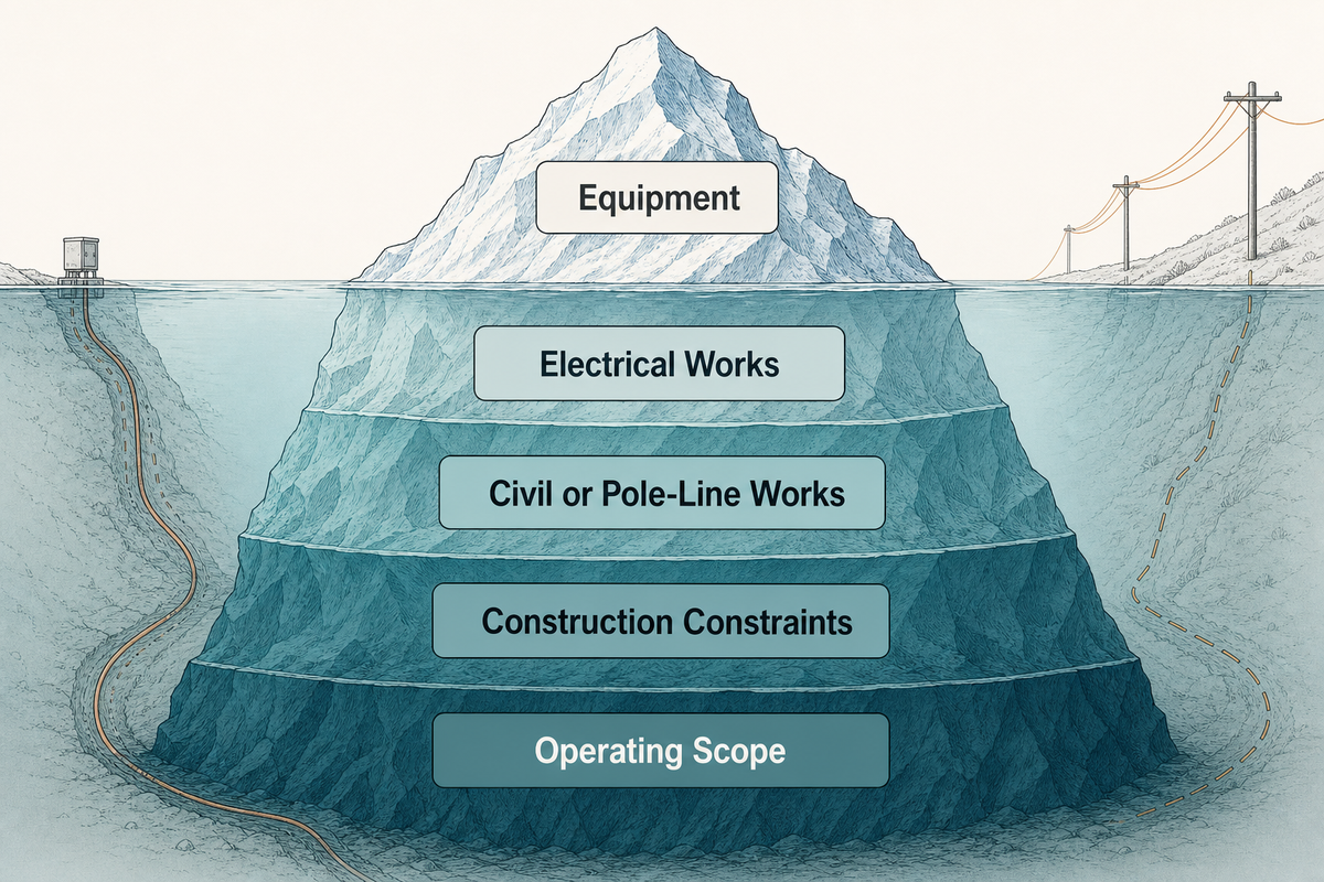
The relative cost of pad-mounted versus pole-mounted architecture can’t be determined from a transformer price alone. A pad-mounted project may include a pad, trench, duct, underground cables, terminations, drainage, warning systems, protective barriers, and site restoration. A pole-mounted installation may include a pole, crossarms, hardware, conductors, arresters, fuses and switches, line clearance, aerial labor, and vegetation work. Both can involve studies, permits, switching, testing, traffic control, and outage coordination.
The cheapest transformer can belong to the more expensive project. Compare both options against the same installed-scope boundary:
- Equipment: transformer, protection, connectors, accessories, and required test documentation.
- Electrical works: conductor or cable, terminations, grounding, switching, secondary distribution, and protection coordination.
- Civil or pole-line works: pad and drainage versus pole, hardware, aerial route, and access.
- Construction constraints: outage windows, traffic control, surface reinstatement, lifting, crew access, and permitting.
- Operating scope: inspections, vegetation or landscape control, cable records, spares, and emergency access.
This common boundary prevents a false economy built from unmatched quotations. It also makes value engineering useful: the team can see whether a saving comes from transformer configuration, feeder routing, site design, or work transferred to another contractor.
Use a 9-Factor Pad Mount Transformer Decision Matrix
The matrix is qualitative because a utility study must set the actual criteria. Use it to compare the same project boundaries, expose unsupported assumptions, and identify which owner must resolve each open item before a mounting decision is released.
| Decision category | Pad-mounted route asks | Pole-mounted route asks | Acceptance evidence |
|---|---|---|---|
| Network fit | Is underground distribution available or justified? | Is the overhead feeder and pole line suitable? | Approved one-line and utility point-of-connection |
| Utility rule | Does the utility permit the proposed pad-mount configuration and interfaces? | Does the utility permit the pole class, mounting, protection, and conductor arrangement? | Current utility construction standard and written review |
| Site fit | Can the pad, cable path, drainage, and replacement route be preserved? | Can the pole, aerial clearance, road access, and work zone be preserved? | Site plan, profiles, and access drawing |
| Exposure control | How are public, vehicle, water, and landscape risks controlled? | How are line, vegetation, traffic, and pole risks controlled? | Risk review and utility/AHJ comments |
| Interface fit | Do the connector, dead front or approved bushing interfaces match the cable system? | Do the high-voltage bushing, arrester, fuse, and conductor interfaces match the line design? | Approved interface schedule and outline drawing |
| Service access | Can crews test, switch, lift, and replace at ground level? | Can line crews and aerial equipment work safely? | Maintainability and restoration review |
| Growth | Do cable routes, pad geometry, and switchgear allow the planned future state? | Do pole strength, conductor, protection, and line route allow it? | Load forecast and future one-line |
| Installed scope | Are civil, cable, drainage, protection, testing, and reinstatement included? | Are pole-line, conductor, protection, aerial labor, access, and vegetation included? | Common bid-scope sheet with exclusions |
| Responsibility | Who owns the feeder, pad or pole, cable or conductor, protection settings, approvals, testing, and future access? | Responsibility matrix signed before release | |
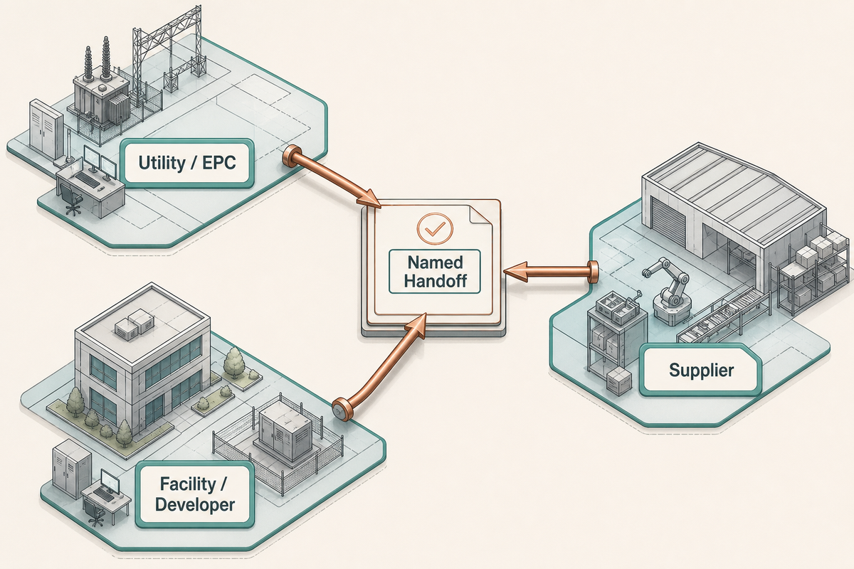
The hidden bottleneck is often a missing handoff, not a missing transformer feature. A utility or EPC defines the network and protection basis. The facility owner preserves the site, access, load information, and operating boundaries. The supplier converts confirmed ratings and interfaces into an engineered submittal. If one role silently assumes another owns cable terminations, civil tolerances, protection devices, or commissioning evidence, procurement can advance while the design remains incomplete.
| Role | Must provide | Must not assume |
|---|---|---|
| Utility / EPC | System one-line, ratings, feeder arrangement, protection and utility requirements | That a catalog transformer defines the complete installation |
| Facility / developer | Load basis, site constraints, access, environmental data, schedule and ownership boundary | That public separation automatically preserves maintenance access |
| Supplier | Compliant proposal, exceptions, outline drawing, interfaces, accessories and test-document list | That an IEEE, ANSI, UL, CSA or NEMA reference alone proves every requested configuration |
If the Pad-Mounted Transformer Configuration Wins, Build the RFQ
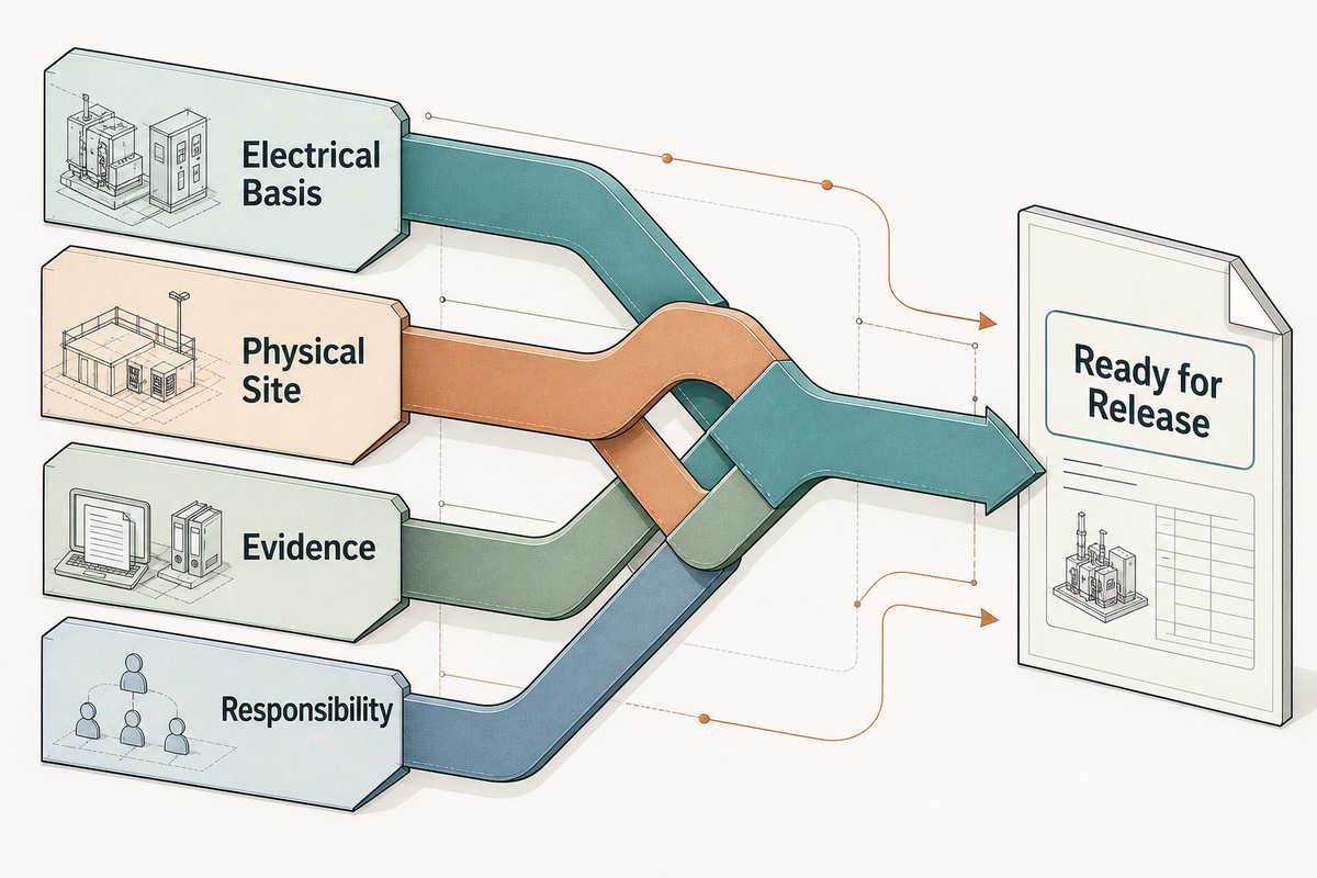
A useful request for quotation links the electrical design to the physical site. “Three-phase pad mount transformer, send price” leaves too many configuration choices open. The RFQ should make the required electrical interface, site conditions, evidence, and division of responsibility explicit. A better handoff includes:
- system one-line and project location;
- rated kVA basis, load profile, expected growth, and critical-load context;
- primary and secondary voltage, frequency, phase, connection, and grounding basis;
- radial feed or loop feed, dead front or other approved primary interface, and utility connection requirements;
- specified impedance, taps, BIL, current limiting fuse or other protection arrangement, and switchgear interface where applicable;
- temperature, altitude, flood or water exposure, corrosion, seismic, noise, and other site conditions required by the engineer;
- pad opening, cable entry, terminal orientation, footprint, lifting/working-access limitations;
- applicable standards, required drawings, routine or special test evidence, nameplate language, accessories, and approved deviations;
- who owns the pad, cable, terminations, protection settings, field testing, energization, and final records.
An RFQ is ready when every rating, interface, site condition, evidence item, and responsibility has an owner. For enclosure construction, configuration language, standards scope, safety, and installation and maintenance fundamentals, use Talite’s existing pad-mounted transformer guide. When the project team has confirmed the pad-mounted route and is ready to discuss a manufacturer proposal, continue to the pad-mounted distribution transformer product page.
FAQs About Pad-Mounted vs Pole-Mounted Transformers
Do pad-mounted transformers cost more than pole-mounted transformers?
No universal price ratio exists. Compare equipment and the complete project scope on a common boundary; existing infrastructure often outweighs the transformer purchase price. The lower equipment quote can still produce the higher installed project cost once civil, cable, pole-line, access, and restoration work are included.
Are pad-mounted transformers safer?
Each architecture controls hazards differently. A locked ground-level enclosure, public and vehicle separation, drainage, working space, and qualified access are separate requirements. Pole-mounted systems reduce casual reach but introduce aerial line-work and pole-access conditions. Use the utility standard, AHJ requirements, and project risk assessment.
Are pad-mounted transformers more reliable?
Not by mounting position alone. Reliability depends on the feeder, protection, fault type, environment, sectionalizing, spare equipment, records, crew access, and restoration method. Compare the complete fault-to-restoration path for the actual site, including how crews locate, isolate, reach, repair, test, and re-energize the affected section.
Can an overhead site be converted to a pad-mounted transformer?
Potentially, but it is a distribution-conversion project, not a simple equipment swap. The utility or engineer must address the underground cable route, riser or transition, protection, pad and drainage, interfaces, easements, testing, and ownership boundaries. Approval also depends on the serving utility’s construction standard and the site’s practical access constraints.
What should a buyer send before requesting a pad-mounted transformer quote?
Send the one-line, kVA and load basis, voltages, phase and frequency, feeder arrangement, interfaces, protection requirements, site conditions, pad and cable-entry information, standards and test-document requirements, schedule, and a clear division of responsibility. The supplier can then identify gaps and issue an engineered proposal instead of guessing.
Why we write this
About Toplit Engineering Insights
Toplit publishes transformer field guides from project routing, factory loss-data discipline, and specification review experience. We help engineering and procurement teams compare transformer types, voltage classes, installation constraints, and quotation evidence before they commit to a build.
- Oil-immersed, dry-type and pad-mounted transformer routes
- Loss data, rating schedules and factory evidence
- IEC / IEEE specification and site-input review
- Factory-direct transformer engineering support
Contact Profile
Talk with the Toplit Transformer Team
Company
Toplit Transformer Engineering Team
Toplit Transformer Engineering Team
Factory base
Hai'an, Nantong, Jiangsu, China
Hai'an, Nantong, Jiangsu, China
![Pad-Mounted Transformer: How It Works [2026 Guide]](https://toplit-transformer.com/wp-content/uploads/2026/08/pad-mounted-transformer-guide-featured-150x150.png)
![Single Phase Pad Mounted Transformer Guide [2026]](https://toplit-transformer.com/wp-content/uploads/2026/08/single-phase-pad-mounted-transformer-guide-featured-1-150x150.png)