Get in touch with Toplit Transformer Co., Ltd Company

Electrical distribution system design turns a load model into traceable choices about voltage, topology, feeders, transformers, protection, grounding, monitoring, and approval. This design process focuses on industrial and commercial facilities. Utility-planning metrics and grid trends appear only where they clarify a boundary or operating scenario.
Updated August 2026 · By XCX
Quick Specs
| Primary scope | Industrial and commercial facility distribution |
| Design stages | 7, from design basis to procurement buyoff |
| Freeze checks | 4 synchronized records |
| Core studies | Load flow, short circuit, coordination, grounding, harmonics, reliability |
| Approval boundary | Qualified professionals and the authority having jurisdiction |
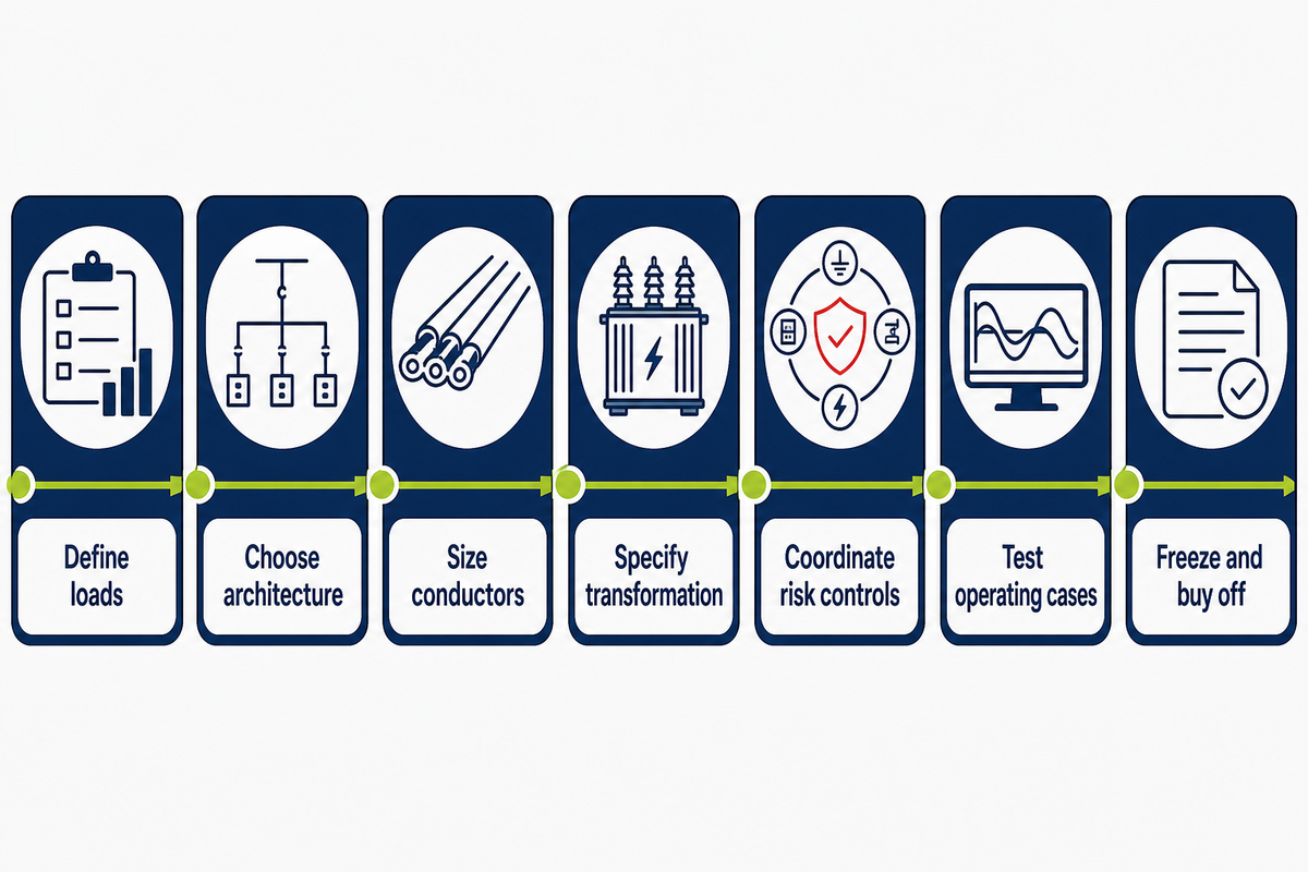
Electrical distribution system design is a seven-stage evidence chain: define loads, choose topology and voltage, size feeders and transformers, coordinate protection, test operating scenarios, then reconcile drawings, models, and procurement data before release.
TL;DR
- No universal spare-capacity percentage replaces named future-load scenarios.
- Transformer kVA is a starting point, not a purchase specification.
- Manual voltage-drop calculations don’t replace load-flow or motor-starting studies.
- Protection requires fault duty, interrupting rating, withstand, grounding, and time-current coordination.
- Design freeze means four records agree: load schedule, study model, single-line diagram, and procurement data.
What Must an Electrical Distribution System Design Deliver?
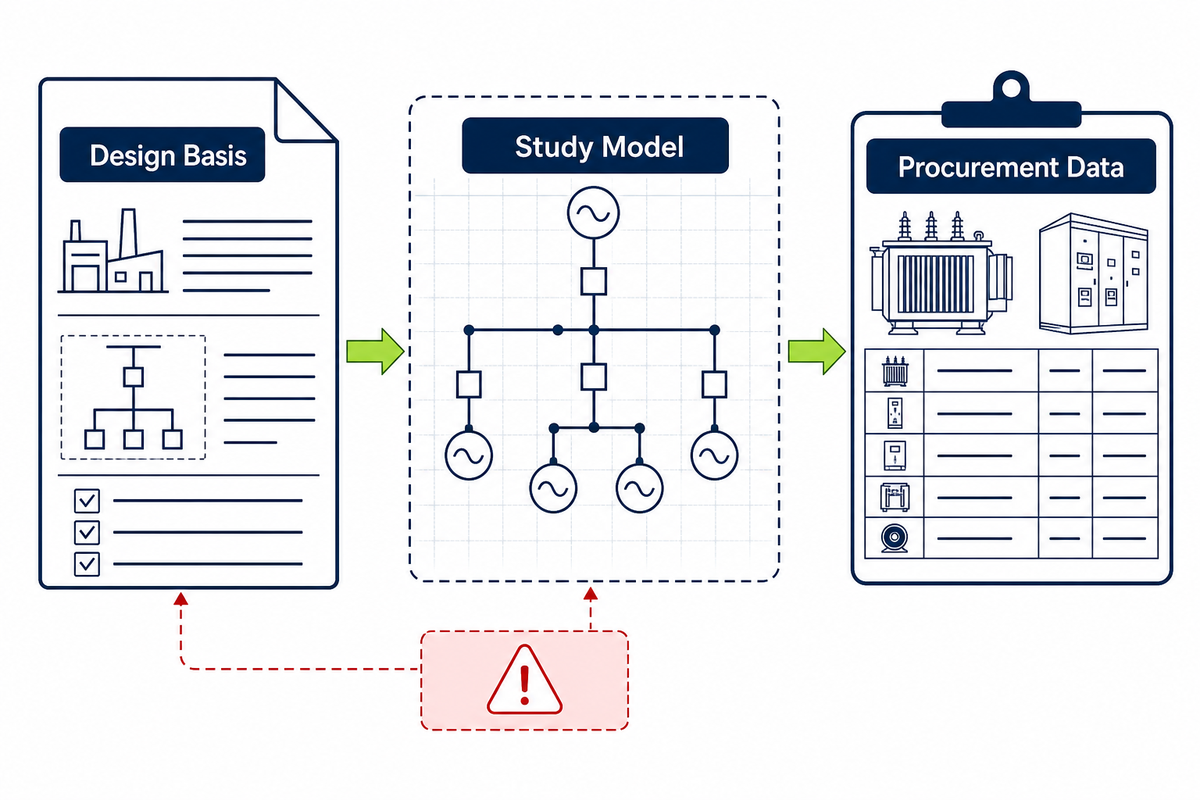
Finished power distribution design for industrial facilities is more than a single line diagram. That controlled package connects load assumptions to system ratings, protection settings, equipment schedules, routing, study results, code compliance, unresolved risks, and approval records so another engineer can reproduce each major decision.
DOE describes distribution-system build-out as an architecture problem involving structure and coherence. At facility level, a changed motor load must propagate through the load schedule, power flow model, feeder rating, transformer duty, fault calculation, protection scheme, cable route, and equipment request. Changing one drawing alone is a warning sign.
Input registers should name the service entrance, sources, voltage levels, loads, demand, power factor, nonlinear behavior, environment, growth, and approval owners. Outputs include design criteria, schedules, study files, settings, routing, grounding, and open items.
Common mistake
Teams sometimes approve a drawing while the study model still contains an older transformer impedance or feeder length. Superficially complete files may then describe different electrical systems.
This guide addresses premises distribution in industrial and commercial facilities. Utility affordability, rates, non-wires alternatives, and system-wide investment portfolios belong to a broader planning process.
Step 1: Build the Design Basis and Load Model
The design basis separates connected electrical loads from diversified demand, starting duty, essential loads, nonlinear behavior, and future scenarios before equipment is sized. Every load carries an operating case, source, owner, and confidence level; otherwise an attractive total can hide simultaneous peaks or severe transient duty.
7-Stage Design Basis-to-Buyoff Chain
A seven-stage chain links each initial assumption to the final approved equipment request.
- Define loads — record duty, coincidence, starting behavior, power factor, harmonics, and ownership.
- Choose architecture — select topology, voltage levels, sources, and restoration path.
- Size conductors — check ampacity, voltage profile, route, losses, and physical installation.
- Specify transformation — translate load cases into transformer duty and connection needs.
- Coordinate risk controls — study faults, protection, grounding, arc and power quality requirements.
- Test operating cases — model normal, contingency, starting, growth, and bidirectional flow.
- Freeze and buy off — reconcile the model, drawings, schedules, data sheets, and approvals.
Each load schedule should record tag, quantity, kW or kVA, voltage, phase, power factor, duty, demand factor, starting method, and operating case. Add harmonic or regenerative behavior for converters, inverters, welders, solar generation, and battery storage.
Scenario 1 — the expansion that should not be a percentage: a plant has a proposed 90 kW compressor, a committed 45 kW process line, and a possible warehouse addition with no approved equipment list. Base case excludes all three. Committed-growth includes the compressor and process line with actual duty. Credible-upper reserves route, switchgear space, monitoring, and a warehouse connection point. Applying 25% to every component would conceal which load is real and could oversize some feeders while missing the compressor’s starting voltage drop.
How do you design a distribution system?
Start with an approved design basis and operating load cases. Define the utility interface, voltages, reliability objective, restoration needs, and environment; compare topology options; size feeders and transformers; then run power flow, fault, protection, grounding, and operating-scenario studies. Finally, reconcile every load, impedance, rating, setting, and connection across the model, single-line diagram, and procurement data before qualified approval.
Do
- Name each operating scenario.
- Record who owns every assumption.
- Separate committed and speculative growth.
- Model motor starting and nonlinear loads.
Don’t
- Add one percentage to every load.
- Treat connected kW as peak demand.
- Hide unknown loads inside spare capacity.
- Freeze equipment before utility inputs arrive.
Step 2: Select System Topology and Voltage Levels
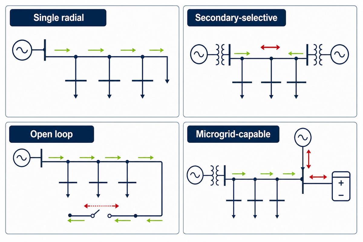
Topology and voltage selection for a distribution network should follow restoration needs, load concentration, route length, fault exposure, maintenance strategy, utility constraints, system performance, and acceptable outage scope. Even when utility inputs are pending, radial systems favor simplicity; alternate-source and loop arrangements improve continuity but add switching, protection, operating, and verification requirements.
Higher primary distribution voltage can reduce current and losses but changes insulation, switchgear, clearances, and testing. Lower secondary distribution voltage may simplify loads while raising current, voltage drop, and feeder size. Compare the whole system, not cable cost alone.
| Arrangement | Best-fit condition | Required study focus | Limitations / Not suitable for |
|---|---|---|---|
| Single radial | Noncritical load, simple operation | Voltage drop and fault clearing | Not for loads that cannot accept one upstream outage |
| Expanded radial | Several load centers from one source | Selective coordination by branch | Common source remains a single contingency |
| Secondary-selective | Two transformers serving paired buses | Tie logic, transfer duty, transformer loading | Not for uncontrolled paralleling or mismatched impedances |
| Primary-selective | Two primary sources or feeders | Transfer, interlocking, source fault levels | No benefit if both sources share one failure point |
| Open loop | Restoration by sectionalizing | Switching states and directional behavior | Restoration is not automatic unless controls are added |
| Closed loop | Continuity with multiple feed paths | Power flow, circulating current, directional protection | Not for sites without skilled operations and coordination |
| Spot network | Dense critical load center | Network protection and reverse power | Cost and complexity exceed typical small-site needs |
| Generator-backed bus | Defined essential loads | Transfer, grounding, short-circuit contribution | Generator capacity and transient response constrain load pickup |
| Microgrid-capable | Local generation and storage with islanding need | Bidirectional flow, controls, protection modes | Not justified without an operating and cybersecurity basis |
Installation method also narrows the equipment set. An outdoor overhead service may lead readers to pole-mounted transformer system options, while an indoor medium-voltage room may require a medium-voltage dry-type transformer configuration. Those pages are product-family starting points, not substitutes for project studies.
What are the four types of distribution systems?
No universal four-type taxonomy exists. Facility guides often group arrangements as radial, loop, primary-selective, and secondary-selective; other sources classify alternating versus direct current, overhead versus underground, or primary versus secondary voltage. State the taxonomy, then test each option against outage scope, switching time, fault current, maintenance isolation, operating skill, and expansion. Labels alone do not establish reliability.
Step 3: Size Feeders and Check Voltage Drop
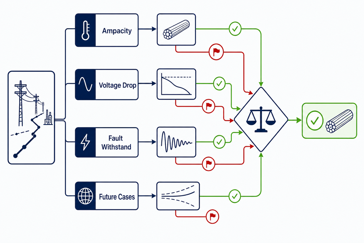
Distribution feeder selection combines current, conductor ampacity, impedance, route length, temperature, fault withstand, voltage regulation, system losses, and future cases. Manual voltage-drop equations provide a first check; motor starting, meshed paths, multiple sources, and sensitive voltage profiles call for validated load flow analysis.
TxDOT’s public calculation guidance makes an important boundary visible: resistance values depend on conductor material, size, length, and temperature, successive circuit segments must be accumulated, supply variation consumes part of the voltage tolerance, and the served equipment sets the acceptable limit. Its roadway-lighting percentages do not become industrial design limits; the method shows why every assumption must be named.
25°CTxDOT resistance-table basis
240 Vroadway example service
480 Vroadway example service
2%source-variation allowance in that manual
Illustrative 3-phase voltage-drop check
Assume 480 V line-to-line, 240 A, power factor 0.90, a 300 ft one-way route, and illustrative conductor impedance R = 0.06 Ω/1,000 ft and X = 0.04 Ω/1,000 ft. With sin φ = 0.436:
ΔV = √3 × I × (R cos φ + X sin φ) × L
ΔV = 1.732 × 240 × [(0.06 × 0.90) + (0.04 × 0.436)] × 0.300 = 8.91 V.
Percent drop = 8.91 ÷ 480 × 100 = 1.86%.
Here, 1.86% is not a conductor approval. Omitted inputs include manufacturer impedance data, conductor temperature, raceway grouping, harmonics, unbalance, terminal voltage, upstream drop, starting current, protection, fault withstand, installation code, and economic loss. If the 240 A load is a large motor, a separate motor-starting study must check transient voltage drop. IEEE 3002.2 describes load-flow and voltage analysis as a system modeling and validation task for industrial and commercial power systems.
Scenario 2 — the route changed after sizing: a feeder was estimated at 300 ft, but coordinated routing around a fire compartment increased the installed path to 460 ft and added another loaded segment. Original current stayed the same, so the equipment schedule looked unchanged. Voltage profile did not. Updating only the cable schedule would miss the model impact; route, impedance, protective-device clearing, served-equipment tolerance, upstream drop, conductor temperature, and motor-starting behavior all need review before release.
Step 4: Select the Distribution Transformer from the Load Case

Transformer selection starts with diversified kVA and then adds phase, primary and secondary voltage, connection, taps, impedance, losses, ambient, enclosure, cooling, noise, grounding, fault duty, regulation, harmonics, installation, and expansion. Nearest standard kVA is only a first-pass candidate, never a complete purchase specification.
Load-Case-to-Transformer Duty Sheet
A duty sheet converts operating load cases into vendor-comparable transformer requirements and unresolved questions.
Consider illustrative load groups of 120 kW at 0.85 power factor and 0.80 coincidence; 60 kW at 0.95 and 0.70; and 30 kW at unity power factor:
- Group A: 120 ÷ 0.85 × 0.80 = 112.94 kVA
- Group B: 60 ÷ 0.95 × 0.70 = 44.21 kVA
- Group C: 30 ÷ 1.00 × 1.00 = 30.00 kVA
- Diversified total: 112.94 + 44.21 + 30.00 = 187.15 kVA
- Illustrative committed-growth case: 187.15 × 1.25 = 233.94 kVA
Here, a 250 kVA unit becomes a first-pass candidate, not the answer. Using 25% is an assumption for this worked scenario, not an industry rule. Final selection must test future loads, temperature, cyclic duty, motor starting, harmonic heating, impedance, short-circuit contribution, voltage regulation, losses, overload policy, redundancy, physical access, fire requirements, acoustic limits, and current market-specific standards.
For an overhead single-phase project, use the single-phase pole-mounted transformer specification page to organize RFQ inputs. Larger network or utility-interface work can start with utility transformer project requirements. Liquid-filled installations should also define the oil-immersed distribution transformer duty and site containment boundary.
RFQ checklist — copy these into your quote request:
| Parameter | Recommended range | Why it matters | How to verify |
|---|---|---|---|
| Rated power | Not established yet, kVA | Must follow verified load cases | Approved load schedule and study model |
| Primary voltage | Not established yet, V or kV | Sets insulation and utility interface | Utility service data |
| Secondary voltage | Not established yet, V | Must match utilization system | Single-line diagram and load list |
| Frequency and phase | Not established yet, Hz / phase | Defines system compatibility | Project design basis |
| Impedance | Not established yet, % | Affects fault current and regulation | Vendor guaranteed-data sheet |
| Loss evaluation | Not established yet, W | Changes lifecycle operating cost | Certified test report and bid evaluation |
| Ambient and installation | Not established yet, °C / altitude m | Affects thermal duty and enclosure | Site data and vendor exceptions |
| Taps and connection | Not established yet, % / vector | Affects voltage and grounding behavior | Study model and approved data sheet |
Screen regulatory scope rather than assuming it. Current 10 CFR 431.192 defines covered U.S. categories by voltage, 60 Hz frequency, capacity, and exclusions. IEEE C57.12.20, C57.12.00, and C57.12.01 describe different scopes; none proves a Talite model fits a project.
34.5 kVcovered input-voltage ceiling
600 Vcovered output-voltage ceiling
10–5,000 kVAliquid-immersed range
15–5,000 kVAdry-type range
IEEE C57.12.20-2023 states an overhead-type scope of 500 kVA and smaller; verify the exact category before applying it.
Step 5: Coordinate Protection, Grounding, and Power Quality
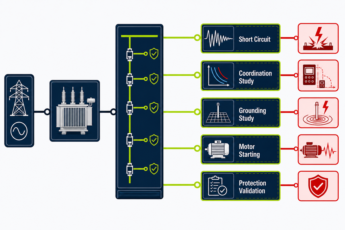
Overcurrent protection must interrupt available fault current, withstand abnormal duty, isolate the intended section, coordinate across time-current curves, and agree with the grounding system. Power quality checks address harmonics, voltage events, unbalance, reactive power, power factor correction, capacitor banks, and sensitive loads under defined operating conditions.
“A percentage from one table may be an allowance or starting point; it does not replace fault-duty, inrush, withstand, interrupting-rating, and coordination checks for the actual transformer circuit.”
The forum shows a recurring confusion, but its 2008 opinions are not code evidence. Calculate faults with actual sources, impedances, motors, and topology; compare duty with switchgear and circuit breakers; then plot protective devices against conductor damage, transformer withstand, inrush, and load behavior.
| Check | Minimum inputs | Failure addressed | Approval owner | Limitations / Not suitable for |
|---|---|---|---|---|
| Load flow | Sources, loads, impedance, taps | Low or high steady-state voltage | Design engineer | Does not prove transient performance |
| Short circuit | Source strength, X/R, motors, topology | Equipment duty exceeded | Protection engineer | Must cover minimum and maximum fault cases |
| Coordination study | Device curves, settings, damage curves | Excess outage or equipment damage | Protection engineer | Selective coordination may conflict with speed |
| Grounding study | Source connection, electrodes, fault path | Unsafe touch potential or poor fault detection | Electrical engineer | Method depends on system and jurisdiction |
| Motor starting | Locked-rotor current, inertia, source model | Voltage collapse or stalled acceleration | System and process engineers | Steady-state voltage drop is insufficient |
| Harmonic study | Spectra, impedance, capacitor banks | Heating, resonance, harmonic distortion | Power-quality engineer | Needs realistic converter operating states |
| Arc-energy review | Fault current, clearing time, work method | Personnel thermal exposure | Safety and engineering owners | Does not replace de-energized work planning |
| Power-factor review | kW, kvar, tariffs, harmonics | Excess current and reactive power cost | Energy and system engineers | Capacitor banks can create resonance |
| Protection validation | Approved settings, test method, as-built data | Installed settings differ from study | Commissioning authority | Paper settings alone do not prove field state |
Common failure modes that a sizing shortcut misses
Wrong transformer impedance can raise fault duty or delay protection. Grounding changes alter zero-sequence current; capacitor banks can create resonance; a closed tie can raise fault current; and field settings can differ from the approved study. Verify nameplates, settings, and switching states against the operating model.
Step 6: Test Reliability, Distributed Resources, and Monitoring
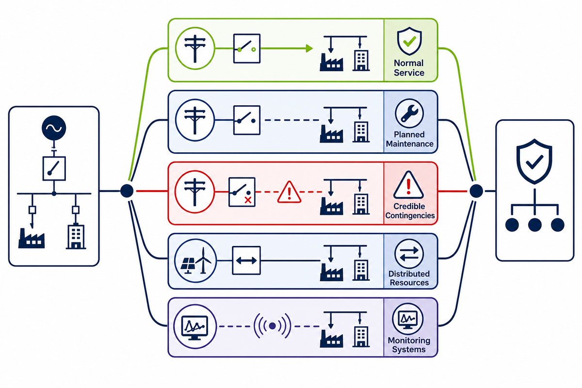
Reliability analysis tests normal service, planned maintenance, credible contingencies, restoration, load growth, distributed resources, and monitoring systems as separate cases. Grid reliability metrics can prioritize work toward reliable power, but feeder, transformer, and protection ratings still come from project-specific electrical models and acceptance criteria.
SAIDI measures average interruption duration, SAIFI measures average interruption frequency, and CAIDI represents average restoration time for interrupted customers. These are outcome metrics. They can also help a utility identify where reliability actions deserve attention, yet they do not directly size a facility conductor or transformer. Facility criteria should instead name acceptable outage scope, restoration time, essential load, maintenance state, and single-contingency behavior.
Solar generation and battery storage can reverse power flow, change voltage, alter fault contribution, and create protection modes. Remote controls add cybersecurity questions: authentication, access control, data integrity, communications loss, safe fallback, network monitoring, and change ownership.
An illustrative operating matrix might compare 100%, 75%, and 50% load at 480 V and 60 Hz, plus 5 s and 10 s motor-start cases; actual cases come from the approved design basis.
Scenario 3 — the normal-open tie that became normal-closed: operations closes a tie to improve flexibility during maintenance. Closing it changes power flow and raises fault contribution at part of the switchgear. If the study model keeps the tie open, coordination and equipment duty no longer represent the operating system. Minimum fault current, directional behavior, transformer loading, interlocks, and restoration instructions also change. Switching restrictions, revised ratings, or new settings may be required before the state is allowed.
Resilience cases may include flood, wildfire, seismic exposure, vegetation, physical access, extreme temperature, and long replacement lead time. Apply them only when the site hazard basis requires them.
Step 7: Freeze the Design and Prepare the Procurement Handoff
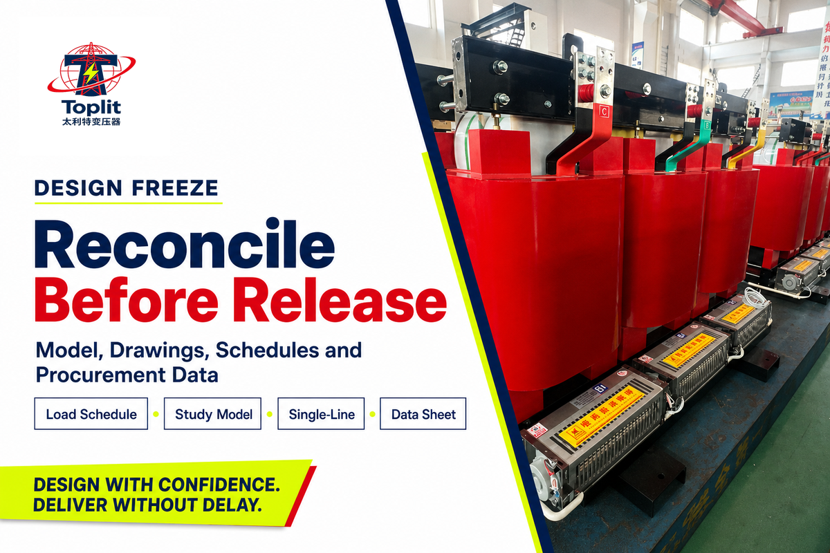
Design freeze is a controlled technical reconciliation, not a calendar date. Before release, the load schedule, study model, single-line diagram, and procurement data must describe the same ratings, impedances, connections, operating states, and unresolved exceptions for comparison and formal approval.
Four-Check Design Freeze Gate
Four synchronized records must agree before a distribution design is released for procurement.
- Load Schedule: every connected, diversified, starting, essential, and future load has a current owner and case.
- Study Model: sources, conductor impedance, transformer ratings, taps, switching states, protective devices, and loads match the design basis.
- Single-Line Diagram: voltage levels, connections, grounding, ratings, metering, and normally open points match the model.
- Procurement Data: vendor-facing sheets state requirements, assumptions, tests, documents, exceptions, and items not yet established.
Release fails if one record conflicts. For example, a 250 kVA drawing cannot coexist with a 300 kVA model entry and an RFQ that omits impedance.
Procurement teams can use distribution transformer manufacturer evidence to ask for comparable documents, tests, deviations, and guaranteed data. Procurement should compare the same duty, scope, and acceptance evidence across offers, not certificate counts.
Key takeaway
A design is ready to buy only when its load schedule, study model, single-line diagram, and equipment request describe the same system.
What Changes a Modern Distribution Design?
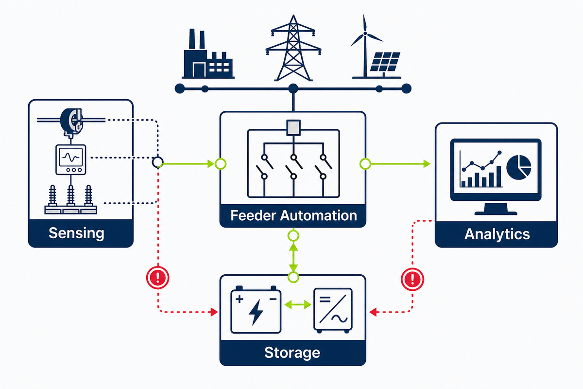
Modern design should minimize power losses, improve energy efficiency, and maintain power where electrification, load growth, bidirectional flow, storage, or automation changes the basis. Smart grid features belong only when they answer a defined reliability, maintenance, safety, expansion, or operating question.
Uncertainty, not gadget count, drives the change. Static peak-demand assumptions become less dependable when electric loads, on-site generation, battery dispatch, or flexible demand reshape power flow. Model credible states affecting capacity, voltage regulation, fault conditions, protection, and restoration.
DOE describes two-way communications, sensing, feeder automation, storage, adaptive operation, and analytics. Facility requirements must state what measurements support decisions, what happens on communications loss, who controls switching, and how changes are validated.
The April 2024 U.S. final rule set amended standards for covered units manufactured on or after April 23, 2029. By contrast, the June 15, 2026 document is a request for information, not a replacement final rule. For a 2029 procurement, use a vendor verification checklist at RFQ release and recheck current law and category before purchase.
For adjacent high-voltage planning, Talite’s 110 kV power transformer planning guide explains a different equipment scale. Keep that transmission or substation context separate from the facility-level examples in this article.
Frequently Asked Questions
What does an electrical distribution designer do?
An electrical distribution designer converts operating requirements into coordinated sources, voltages, feeders, transformers, switchgear, protection, grounding, studies, drawings, procurement data, and controlled technical approval records.
Work begins with load requirements and continues through equipment selection, routing, voltage drop, fault current, protection coordination, power quality, reliability analysis, and future expansion. Designers also keep the load schedule, study model, single line diagram, and procurement data aligned. Depending on the jurisdiction and project, a licensed professional and the authority having jurisdiction must approve the applicable design and drawings.
How do you design an electrical distribution panel?
Panel design starts with calculated demand, voltage, phase, available fault current, enclosure conditions, isolation needs, outgoing circuits, physical access, and the coordinated upstream protection scheme.
Designers check bus and main ratings, outgoing circuit breakers, interrupting ratings, conductor terminations, load balancing, grounding, spare ways, labels, maintenance access, and coordination with upstream and downstream protective devices. Panelboards must match the single-line diagram and study model. Panel schedules alone cannot establish short-circuit duty, selective coordination, or safe installation.
What is a power distribution system?
Power distribution systems carry electricity from a service, substation, generator, or local energy source through transformers and protected feeders to the loads that use it.
Components can include transformers, feeders, switchgear, panelboards, protection, grounding, meters, controls, solar generation, battery storage, and other distributed energy resources. Utility networks and industrial facility systems share physical principles, but ownership, voltage levels, reliability criteria, safety standards, operating duties, maintenance responsibilities, and formal approval paths differ by project and jurisdiction.
How do you choose a distribution transformer?
Choose a distribution transformer from diversified kVA, voltage, phase, impedance, losses, environment, harmonics, fault duty, installation method, and credible future operating cases, not connected load alone.
Define voltage, phase, connection, impedance, losses, environment, fault duty, regulation, harmonics, and future cases; then compare guaranteed vendor data.
How much spare capacity should an electrical distribution design include?
No universal spare-capacity percentage fits every electrical distribution design; use named base, committed-growth, and credible-upper load cases with explicit owners, review dates, and documented assumptions.
Build base, committed-growth, and credible-upper cases from named loads, duty cycles, temperature, contingency needs, upstream system capacity, and interruption cost. If future demand is speculative, reserve space, routing, monitoring, or modular connection points instead of silently oversizing every conductor and transformer. Apply a numerical allowance only when the owner, utility, jurisdiction, or approved project criterion requires it.
Turn the design basis into a comparable transformer request
Talite Transformer Co., Ltd. has worked in power equipment for more than three decades. Share the load cases, voltage interface, installation conditions, required standards, and unresolved items; the team can discuss a transformer configuration without pretending that an illustrative calculation is a final specification.
Evidence Boundary for This Guide
This article combines current government and standards-scope sources with transparent editorial frameworks for facility distribution design. No project load study, Talite factory test, certification file, customer result, or approved protection setting was supplied for this article. Worked numbers are illustrative. Project-specific engineering and approvals remain with qualified professionals and the authority having jurisdiction. Prepared for publication by XCX for Talite Transformer Co., Ltd.
References & Sources
- Distribution System Design U.S. Department of Energy
- Highway Illumination Manual: Calculating Voltage Drop Texas Department of Transportation
- IEEE 3002.2-2018 Load-Flow Studies IEEE Standards Association
- 10 CFR 431.192 Definitions Electronic Code of Federal Regulations
- IEEE C57.12.20-2023 IEEE Standards Association
- IEEE C57.12.00-2021 IEEE Standards Association
- IEEE C57.12.01-2020 IEEE Standards Association
- Distribution System Reliability Metrics Michigan Public Service Commission
- Grid Modernization and the Smart Grid U.S. Department of Energy

![Single Phase Pad Mounted Transformer Guide [2026]](https://toplit-transformer.com/wp-content/uploads/2026/08/single-phase-pad-mounted-transformer-guide-featured-1-150x150.png)