
Get in touch with Talite Transformer Co., Ltd Company

ISO Certified
pad mounted distribution transformers
Pad Mounted Distribution Transformers by Talite
Choosing a pad mounted transformer by capacity alone leaves too many design details unresolved. Talite reviews the load, primary and secondary ratings, feed arrangement, interface, protection, fluid, enclosure conditions and required project evidence before preparing a project-specific commercial offer.
Request a Quote for Your Project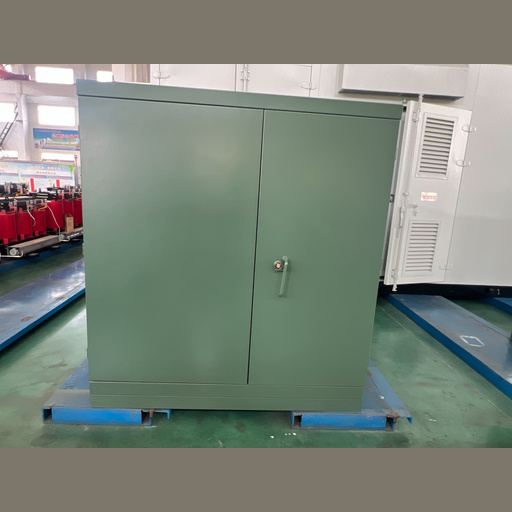
Best fit
3-phase underground distribution projects needing a configured factory-built unit.
Manufacturer-supplied range
45–12,000 kVA, subject to engineering review and applicable scope.
Primary decision
Match the electrical system and network arrangement before comparing commercial offers.
Required output
A project-specific drawing, data schedule, test-document plan and quotation.
Match Underground Distribution Requirements Without Specification Gaps
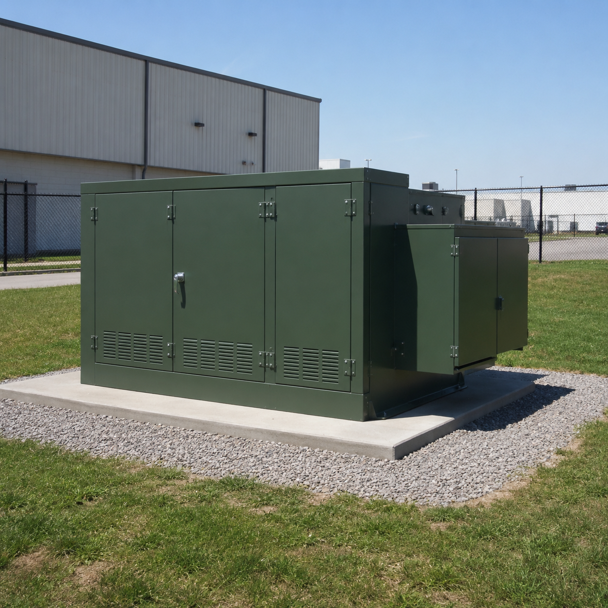
Pad mounted distribution transformers place the transformer and cable terminations inside a tamper-resistant ground-level enclosure. They suit underground distribution systems where overhead equipment or exposed connections conflict with site constraints. Authorized access still depends on clearances, grounding and switching procedures defined by the project engineer.
Application Signal, Not A Sizing Answer
Renewable step-up systems, EV charging, data centers, substation feeder projects and other expanding load categories are increasing demand for 3-phase pad-mount designs, according to a 2024 National Renewable Energy Laboratory demand study. That application trend does not determine a final transformer design. It explains why the RFQ must describe the load profile and operating context, rather than offer a generic application label.
Common Mistake: an incomplete rating creates a specification gap and approval-delay risk because 34.5 kV, 600 V and 2,500 kVA boundaries can change the applicable review path. Engineering review resolves that gap by linking the load, network and evidence inputs before selection. Unlike a catalogue comparison, this approach exposes the trade-off before the quotation is frozen.
Scope Boundary: a manufacturer capability range is not a blanket certification statement. System ratings, capacity, frequency and secondary output determine which regulatory or standards scope may apply. Project review should confirm the selected design against the specification and destination-market requirements.
What Talite Needs Before Engineering
- Rated capacity and expected load profile
- Primary system rating and grounding
- Secondary rating, phase and connection
- Radial or loop-feed network arrangement
- Live-front or dead-front interface requirement
- Protection, switching and accessory schedule
- Fluid preference and site environmental conditions
- Applicable standards, utility rules and test records
1
Electrical Fit
Confirm capacity, turns ratio, frequency, connection, impedance and insulation level against the system study and load.
2
Network Fit
Define feed and interface arrangements with the protection and operating method. These decisions are interdependent.
3
Evidence Fit
List drawings, calculations, certificates, routine tests and witness points needed for approval before production.
Power Distribution System Interfaces
A pad-mount unit can link medium-voltage underground cables to a lower-voltage distribution network; the required voltage transformation, connection points and surge protection must follow the one-line diagram and adjacent switchgear. Treat the equipment as part of the electric power distribution system rather than an isolated green box, because primary and secondary interface decisions affect system reliability.
Application Route
System Context
RFQ Implication
Utility distribution
Distribution lines and underground cables
Provide the utility construction standard and switching scheme.
Commercial and industrial
Commercial complexes or facility power networks
State demand, fault duty, load growth and operating priorities.
Renewable energy
Step-up duty or collection-system interface
Define direction of power flow, duty cycle and protection study.
Data centers and EV charging
Concentrated or fast-changing loads
Submit the load profile, redundancy philosophy and harmonic study basis.
Overhead conversion
Transition from overhead power lines or service drops
Coordinate the underground entry, connection points and ownership boundary.
Single-phase routing
Single-phase or single phase pad requirement
Route to the single-phase pad-mounted transformer family rather than forcing a polyphase design.
Alternate fluid
FR3 fluid or another high-fire-point dielectric request
Obtain project fire, environmental, thermal and material approval.
Site delivery
Proper installation and maintenance planning
Define foundation, access, termination, commissioning and service responsibilities.
Talite Pad Mounted Transformer Range and Configuration Paths
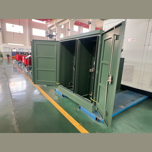
Talite’s supplied product material describes American-style pad-mounted units with a sealed liquid-filled tank and enclosed high- and low-voltage compartments. The published manufacturer range is a preliminary envelope for project review. Actual availability depends on the requested combination, technical standard, utility practice, manufacturing review and approved drawings.
45–12,000 kVA
Manufacturer-supplied capacity envelope
2,400–46,000 V
Manufacturer-supplied primary range
120–24,940 V
Manufacturer-supplied secondary range
30–250 kV BIL
Manufacturer-supplied insulation range
Those upper endpoints cross boundaries used in published U.S. distribution-transformer definitions and the IEEE pad-mounted equipment scope. They therefore require classification and standards review instead of being treated as one uniform product class. An RFQ at 12 MVA or a 46 kV primary has a different evidence path from a conventional 1 MVA unit with a medium-voltage primary and a low-voltage secondary.
“A usable quotation should lock the electrical duty, network arrangement and evidence package together. Changing one field can change the transformer design, drawings, components and commercial terms.”
Standard design route
Use this route when the electrical ratings, interface and accessory schedule align with an established product design. Submittals still need project-specific drawings and a confirmed data sheet.
Engineered design route
Use this route for unusual winding combinations, higher ratings, special impedance, alternate fluid, destination-specific requirements or a detailed utility specification. Additional review may affect dimensions, testing and lead time.
Clarification
Engineering staff mark incomplete, conflicting or unusual requirements before design assumptions harden. Buyers receive a focused question list instead of a nominal selection built on missing system data.
Submittal
Engineering converts the confirmed input into drawings and technical schedules. Hold points should be identified before approval so comments do not arrive after materials or components have been committed.
Production release
Manufacturing begins against the approved technical baseline and agreed commercial scope. Any later change needs a documented assessment of design, cost, schedule, testing and drawing impact.
Fluid and enclosure route
An oil-immersed design, requested FR3 fluid or another dielectric fluid requires project-specific thermal, material, fire and environmental review. If a steel cabinet, special coating or alternate construction is specified, place the material and acceptance criteria in the RFQ instead of assuming a standard enclosure.
Honest version: a broad manufacturer range gives buyers more design paths, but it also increases mismatch risk because not every endpoint shares the same standards class. This manufacturer will not claim one blanket compliance route. Its engineers confirm the offered combination, while production works from the approved baseline. Range width is not proof; the trade-off is flexibility with more disciplined review.
Three-Phase Pad Mounted Transformers: Voltage-to-Load Decision Ladder
The Voltage-to-Load Decision Ladder prevents a common procurement shortcut: selecting a nameplate capacity and postponing the remaining specification fields. Each rung depends on the answer above it. If load behavior, system level or grounding changes, revisit the following decisions before asking a supplier to hold dimensions or price.
Specification trap: a 1 MVA industrial buyer can still receive the wrong secondary current, fault duty or terminal arrangement because capacity does not resolve the ratio and impedance. Engineering staff use the ladder to expose the structural reason for each dependency. A slightly longer input stage is the trade-off for reducing late design rework.
Describe the Connected and Future Load
Provide the present demand, motor starting or cyclic loads, expected expansion, power factor and any harmonic-producing equipment. Connected load alone may overstate or understate the required transformer duty.
Establish the Design Demand and Capacity
Project electrical engineers apply diversity, demand and contingency rules. For a balanced 3-phase planning check, apparent power relates to line rating and current as kVA = √3 × V × A ÷ 1,000.
Lock Both Winding Sides and Connection
State the nominal primary rating, available taps, secondary rating and winding connection. Grounding and neutral requirements affect the usable system, protection coordination and terminal arrangement.
Define Impedance and System Duties
Impedance influences regulation and available fault current. It must be coordinated with protective devices, downstream equipment ratings and any parallel-operation study.
Confirm Insulation and Site Conditions
BIL, altitude, temperature, contamination, flood exposure, corrosion category and seismic criteria can alter the design or enclosure specification. Site data belongs in the RFQ, not in a post-order note.
Freeze the Acceptance Evidence
Specify required routine test reports, guaranteed losses, drawings, certificates and inspection points. A dated City of San Marcos procurement example asks for loss data and serial-number-linked records; it illustrates possible fields rather than a current universal requirement.
| Decision Input | Numeric or Defined Value | Design Dependency | RFQ Evidence |
|---|---|---|---|
| Rated Capacity | kVA | Thermal duty, tank and conductor sizing | Load schedule and design demand |
| Primary Voltage | V or kV | Winding, insulation and interface | Single-line diagram |
| Secondary Voltage | V or kV | Current, terminals and downstream equipment | Load-level schedule |
| Frequency | 50 or 60 Hz | Magnetic design and regulatory classification | Destination system data |
| Impedance | % at rated base | Fault current and regulation | Coordination study target |
| Primary BIL | kV | Insulation coordination | Utility or project requirement |
| Tap Range | % and positions | Winding adjustment | System tolerance |
| Loss Requirement | W at stated test condition | Operating cost and acceptance | Guaranteed-loss schedule |
| Ambient and Altitude | °C and m | Cooling and dielectric performance | Site design basis |
| Sound Limit | dB criterion | Core, tank and site placement | Project acoustic requirement |
This decision table supports specification development; it is not a design approval. Qualified electrical professionals must determine final ratings and protective-device settings from the project’s load-flow, short-circuit, coordination and grounding studies.
Illustrative Scenario: One Arithmetic Screen
An engineer enters a 480 V line rating, 800 A design current and 20% planning headroom; the balanced-load formula returns about 798 kVA. If the project later examines 1,000 kVA at 13,800 V primary and 480 V secondary, balanced full-load current is about 41.8 A primary and 1,203 A secondary; a 5.75% impedance request, 60 Hz duty, or a boundary such as 34,500 V input, 600 V output and 2,500 kVA changes the next checks. This worked example demonstrates data dependencies, not a recommended rating; project studies and engineering approval control the selection.
Terminology Found in Buyer Research
Search language varies: pad mount transformer, 3 phase pad-mounted transformer, three phase pad-mounted transformer, pad-mounted transformer specifications, pad-mounted transformer sizes and live front vs dead front transformer may point to the same buying journey. None of those phrases replaces the project ratings or one-line diagram.
Live-Front, Dead-Front, Radial and Loop-Feed Decisions
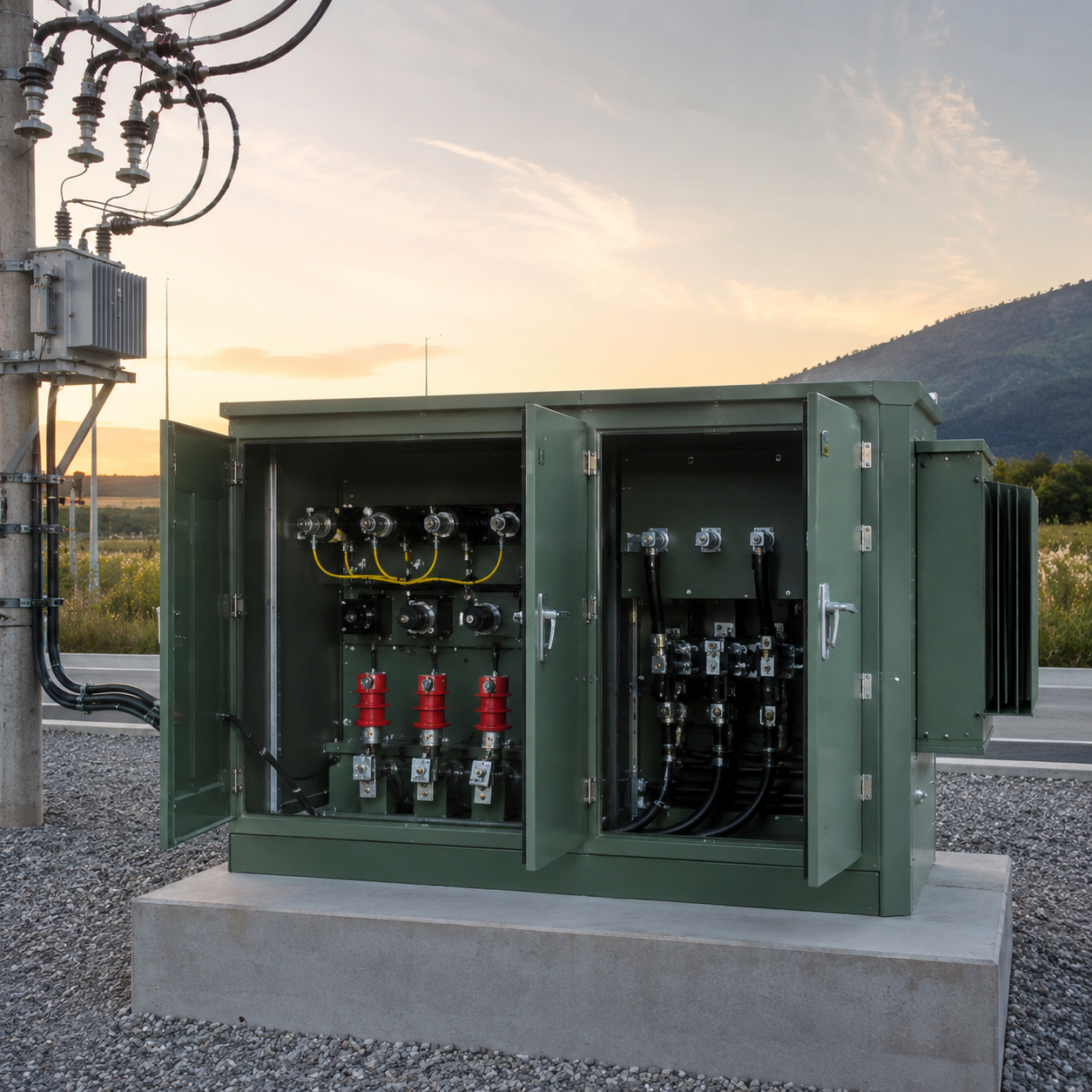
Feed arrangement describes how the transformer sits in the distribution network. Front type describes the high-voltage interface and shielding arrangement. They answer different questions, yet both affect switching practice, accessories, compartment layout and operating procedures.
Arrangement trap: separating feed and front decisions creates mismatch risk because a 34.5 kV loop scheme, its bushings and its operating method form one system. Engineering staff review that trade-off against the one-line diagram. Approved interfaces then map into the compartment layout, and production releases only the confirmed schedule.
Configuration Dependency Map
| Design path | Network condition to define | Interface or hardware consequence | Approval input |
|---|---|---|---|
| Radial feed + live front | Single incoming source | Exposed energized parts may be present inside the opened compartment | Utility construction standard |
| Radial feed + dead front | Single incoming source | Shielded separable connectors may be specified | Connector and bushing schedule |
| Loop feed + live front | Incoming and outgoing circuit path | Switching and compartment layout require joint review | Operating one-line and utility practice |
| Loop feed + dead front | Loop continuity and sectionalizing method | Connector ratings and switch positions must match the scheme | Switching diagram |
| Mineral-oil route | Site permits conventional fluid | Fluid handling and containment criteria apply | Environmental and fire review |
| Ester-fluid route | Project asks for alternate dielectric fluid | Thermal, material and fire-code review may change details | Approved fluid specification |
| Internal primary protection | Protection is integrated in the enclosure | Fuse type and coordination must match available fault duty | Protection study |
| External primary protection | Upstream device provides defined protection | Transformer accessories follow the system scheme | Upstream device data |
| Standard accessories | Routine indication and service needs | Gauges, valves and nameplate follow approved schedule | Accessory checklist |
| Special monitoring | Remote condition data is required | Sensors, auxiliary power and communications need interfaces | I/O and communication schedule |
Do not infer safety from a label
“Dead front” does not make an opened transformer safe to approach. Authorized work practices, isolation, grounding, test procedures and local rules remain mandatory.
Do not separate the options
Feed, front, fusing, switches and bushings form an operating system. Late changes to one selection can trigger layout and component revisions.
Do not copy another utility
Utility standards differ. Supply the destination utility’s latest construction and material requirements with the RFQ whenever they govern the project.
Standards, Enclosure and Engineering Verification
“
Standards references become useful only after the product scope and required evidence are clear. IEEE C57.12.34-2022 addresses certain three-phase pad-mounted distribution transformers at 10 MVA or less, with high-voltage ratings of 34.5 kV or less and low-voltage ratings of 15 kV or less. IEEE C57.12.28-2023 addresses enclosure integrity and coating requirements for pad-mounted equipment.
The honest compliance boundary: neither title by itself proves that a specific production unit satisfies a buyer’s complete specification. The company will not claim that a standards number replaces drawings, test records or project acceptance. That shortcut creates overclaim risk because scope and evidence are different checks.
❮
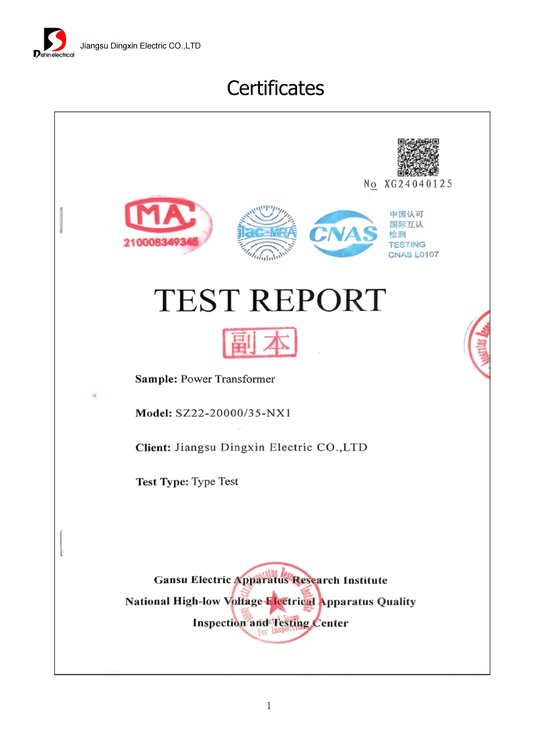
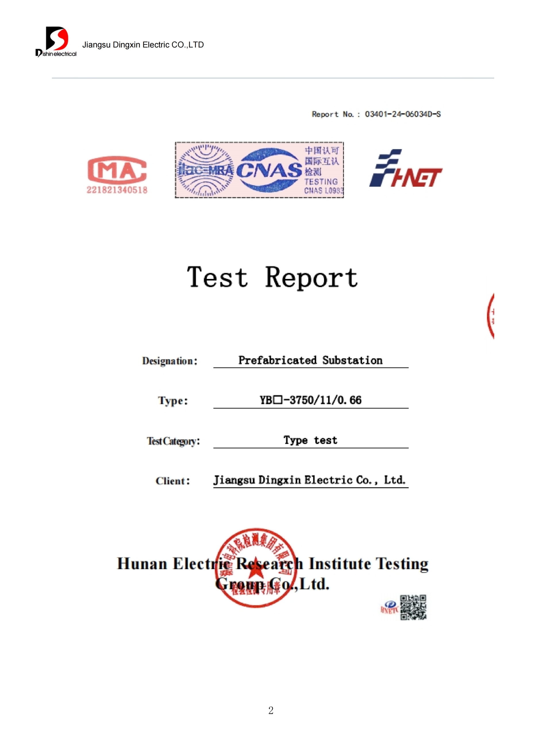
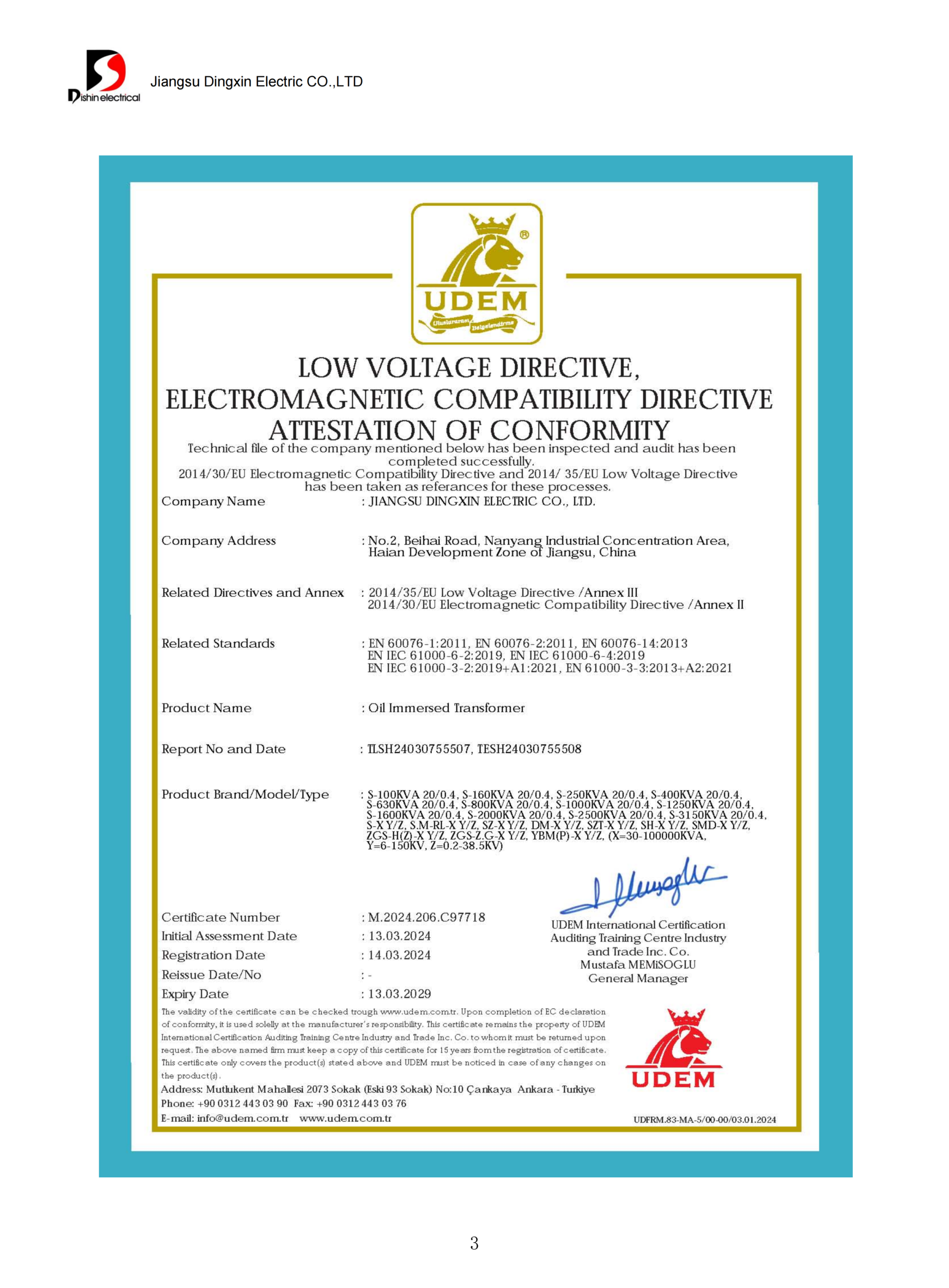
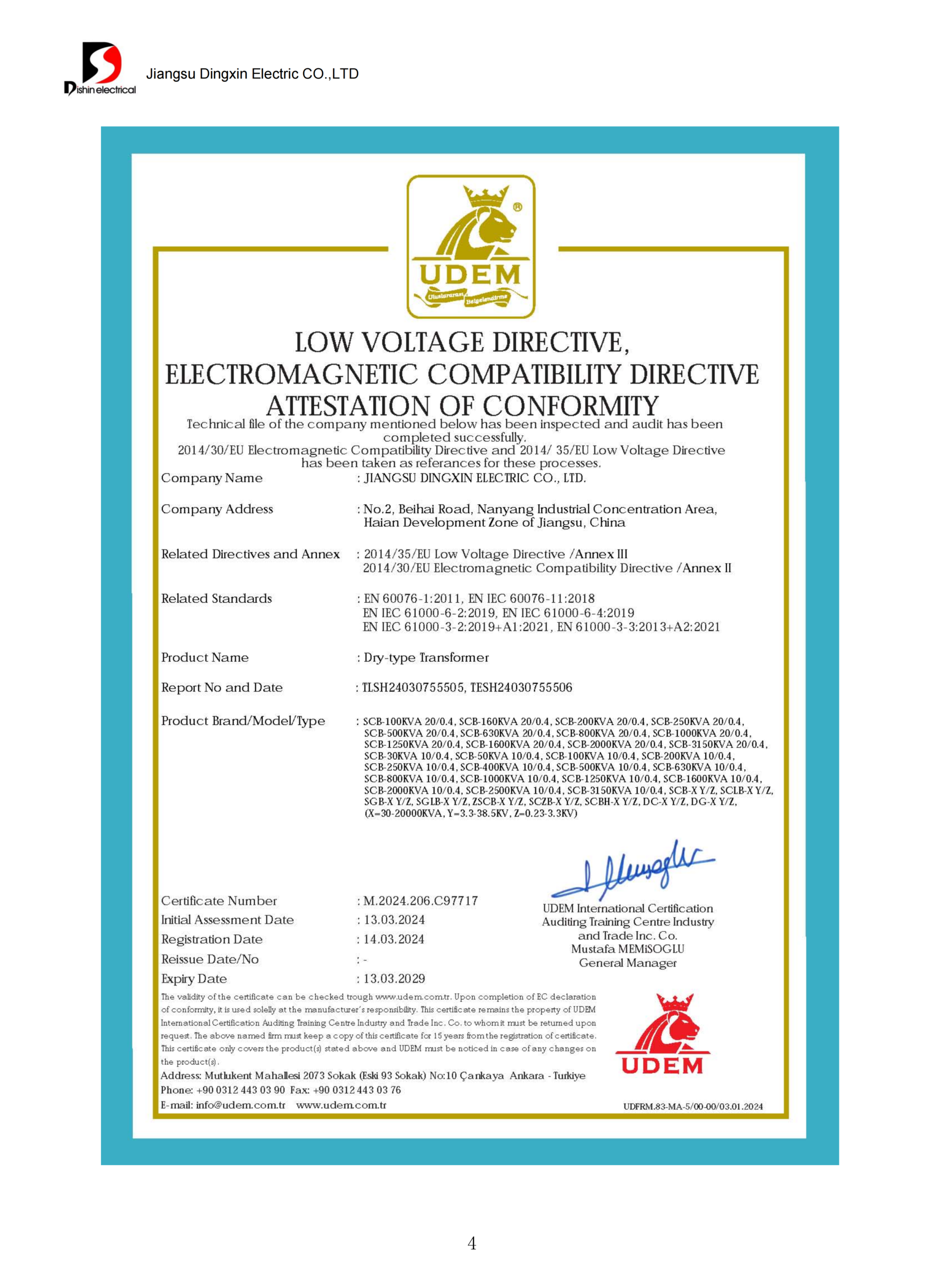
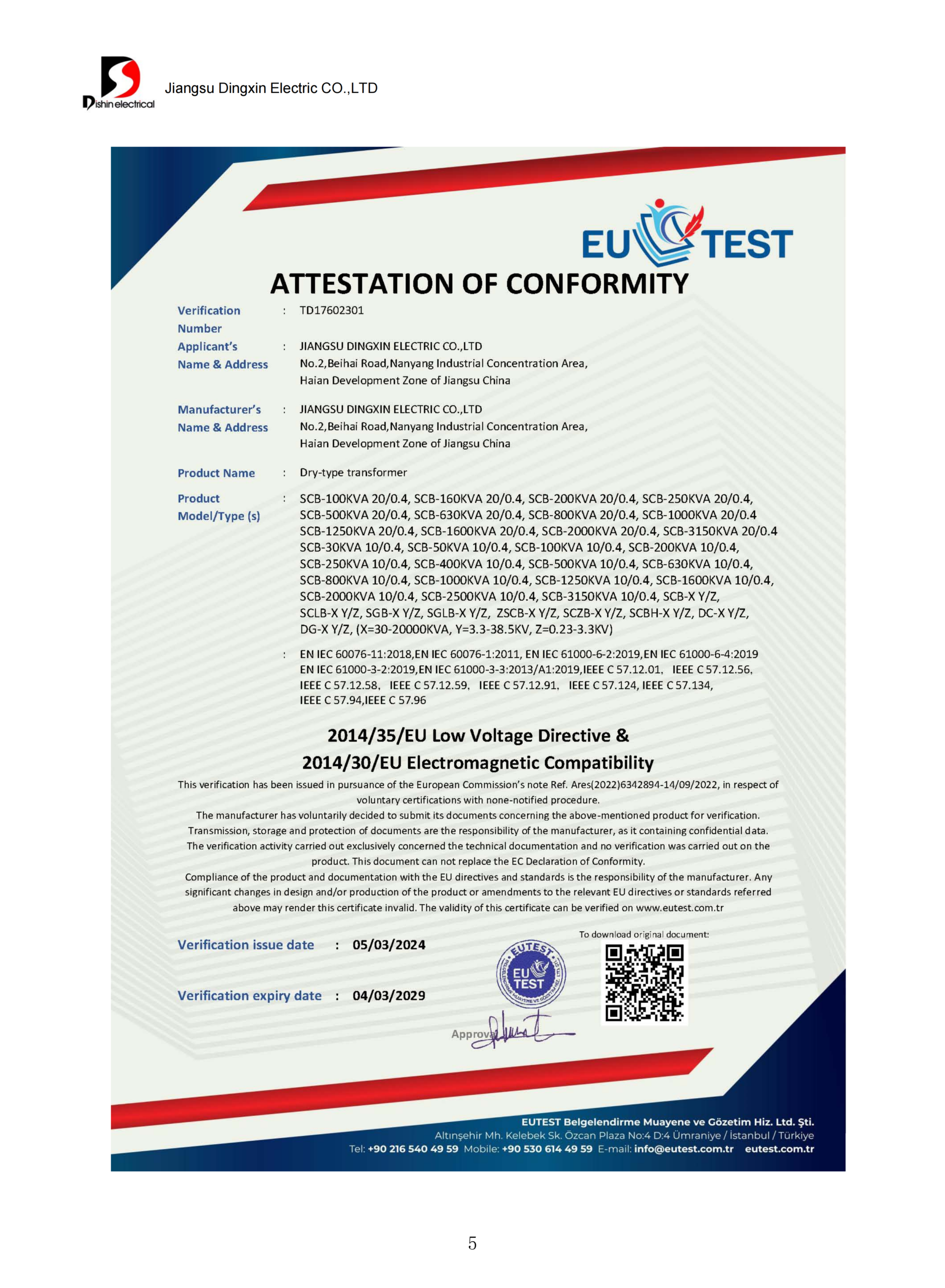
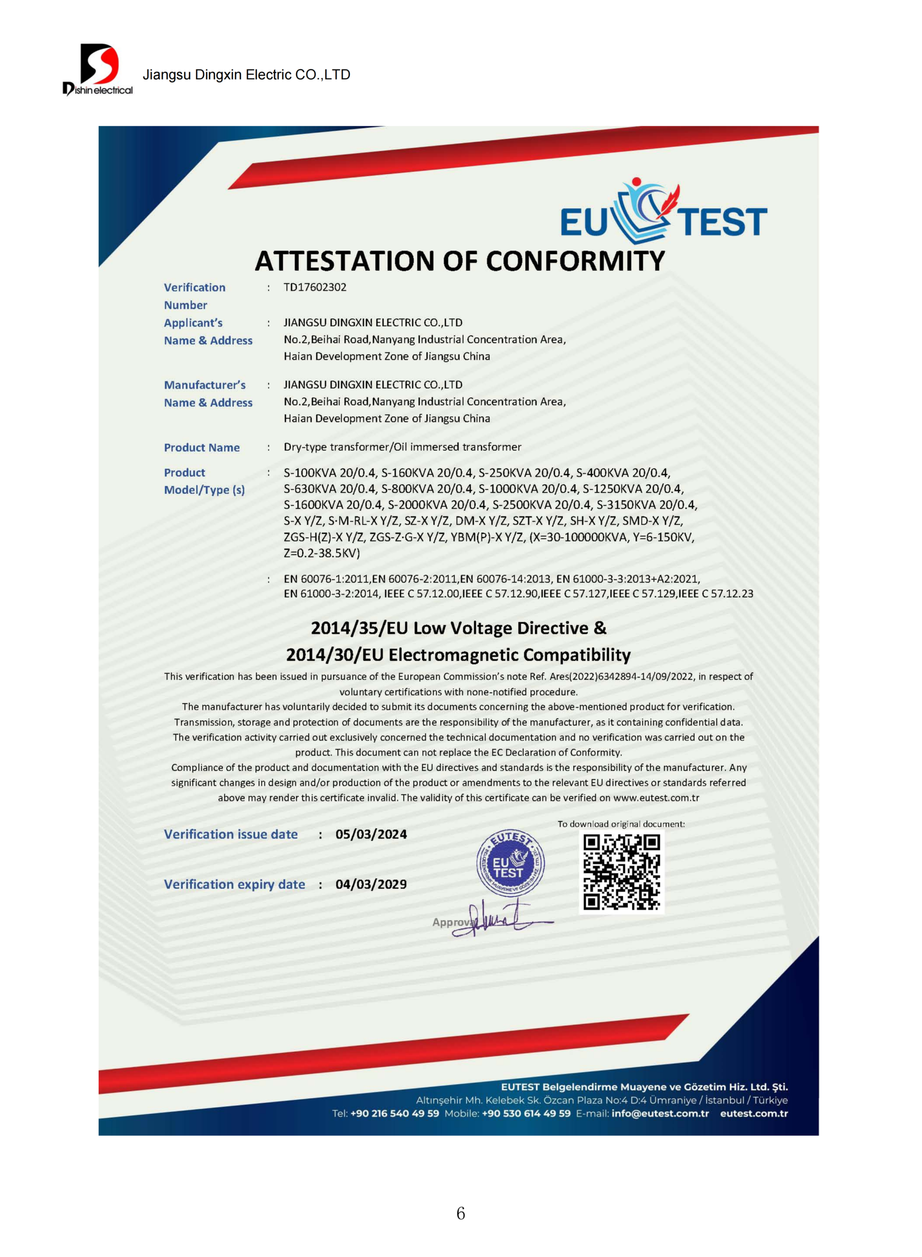
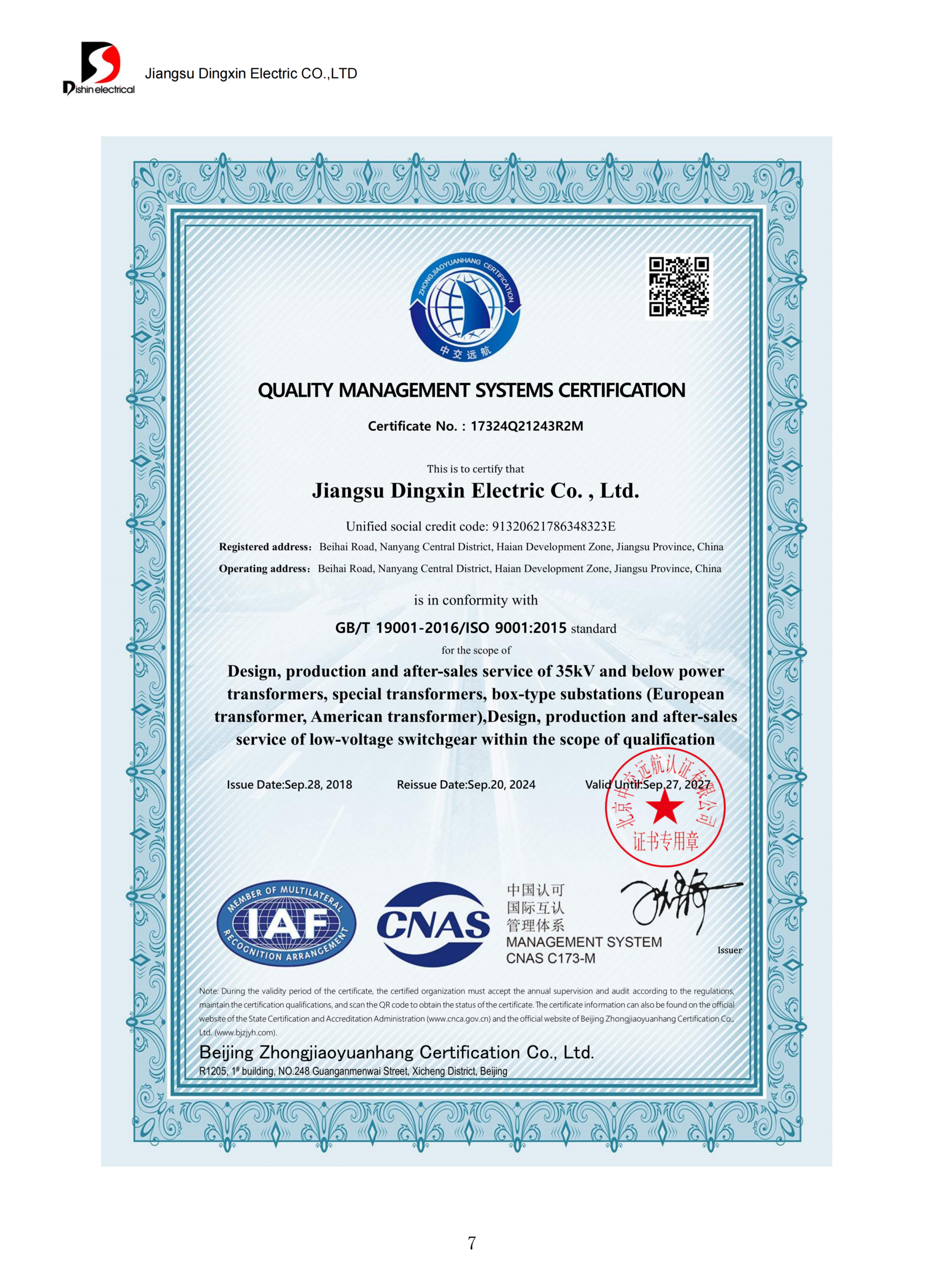
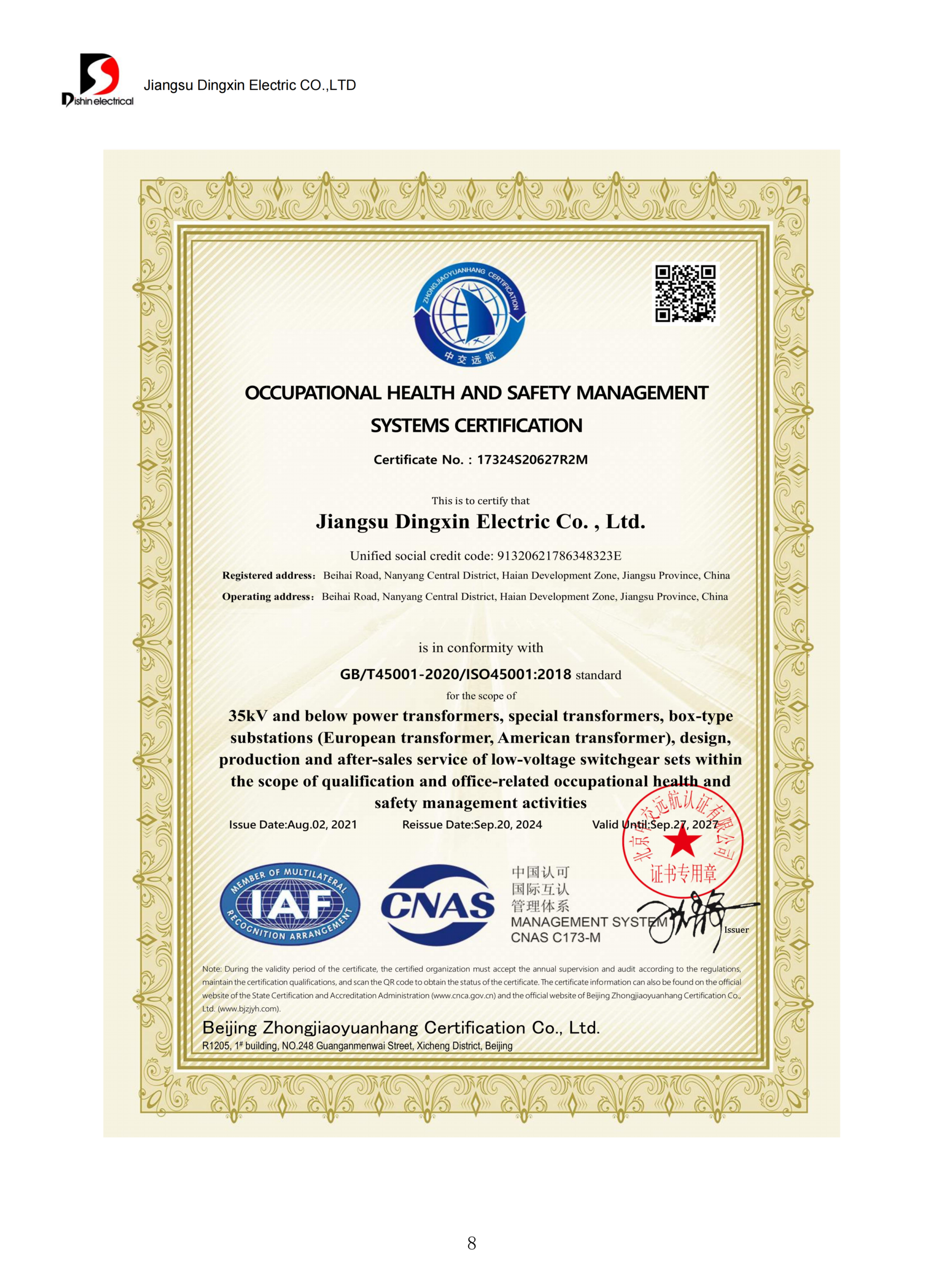



01 / 12
×
![Zoomed Certificate]()
Standards Schedule, Not a Logo List
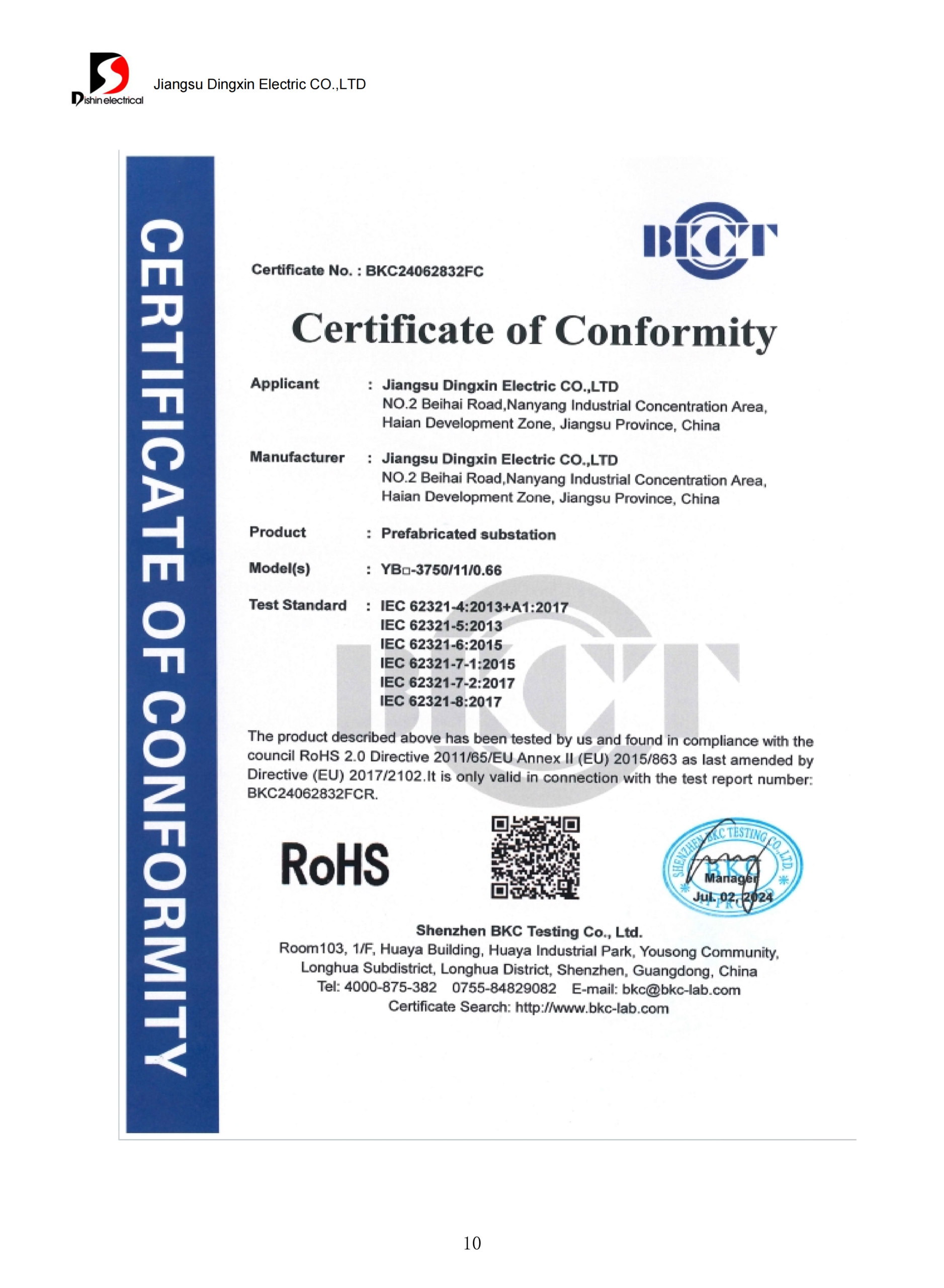
List the applicable ANSI references, IEEE standards, destination regulations, eCFR 10 CFR Part 431 scope and utility rules with their required editions. This keeps electrical and mechanical acceptance criteria tied to the offered design and prevents a general standards statement from standing in for conformity evidence.
A
Published Scope
Check rating limits, product definition, exclusions and edition. This establishes whether a standard or regulation may be relevant.
B
Product Evidence
Review approved drawings, technical schedules, material records, routine test reports and any required type-test evidence for the offered unit.
C
Project Acceptance
Confirm the owner, engineer or utility has accepted the submittal package. Acceptance criteria can extend beyond the cited product standard.
U.S. efficiency scope needs separate review. DOE’s regulatory definition for a covered distribution transformer includes a 60 Hz unit with input voltage of 34.5 kV or less and output voltage of 600 V or less; the cited liquid-immersed classes span 10 kVA to 2.5 MVA. Designs outside those values should not be described as though the same DOE class automatically applies.
Evidence Package to Request
- Approved general arrangement, outline dimensions and total mass
- Nameplate drawing and electrical data schedule
- Primary and secondary compartment arrangement
- Guaranteed no-load and load loss values at the test-basis specified in the specification.
- Routine and special test reports verified in line with the product supplied and linked to the actual serial number of the equipment.
- Insulating-fluid description and applicable material documentation
- Enclosure material, coating system and finish requirements
- Accessory, bushing, connector, fuse and switch schedule
- Special test, inspection and witness-point plan where specified
- Installation, handling, storage and maintenance instructions
Flood exposure, corrosive environments and spill-control obligations are site questions. Site teams should review enclosure specifications, mounting elevation, drainage, foundation, clearances and containment with the local authority. EPA spill-prevention rules are conditional on facility circumstances; they are not a universal transformer accessory list.
Published “pad mounted transformer price” information seldom supports a fair supplier comparison because the scope may exclude essential engineering, testing, logistics or accessories. A lower initial figure may reflect a different system class, conductor content, loss design, protection package or delivery boundary.
The pricing mistake: the cheapest headline number can hide a costly scope gap. That risk exists because losses, accessories, evidence and freight may be excluded. The honest trade-off is to spend more time normalizing the RFQ before assigning value to a 32-year economic study period.
Installation and Maintenance Boundary
Define foundation, handling, cable termination, commissioning support, spare parts and planned maintenance in the commercial comparison. These boundaries influence installed cost, schedule exposure and operating costs even when the transformer nameplate is identical.
Cost Drivers to Normalize
- Capacity, both winding ratings and BIL
- Impedance and guaranteed loss requirements
- Conductor, core, fluid and temperature-rise design
- Radial or loop feed; live-front or dead-front interface
- Fuses, switches, gauges, arresters and monitoring
- Enclosure, coating, environmental and seismic requirements
- Special testing, inspection and documentation
- Packaging, inland handling, shipping term and destination
Silver TCO Method
Compare evaluated purchase cost, estimated loss cost, installation-related scope, maintenance assumptions and end-of-life terms over the same study period. For planning, annual loss energy can be approximated as:
8,760 × [no-load loss + load loss × (average load factor)²] ÷ 1,000
Use watts for losses to obtain kWh per year, apply the project’s energy-value method, and treat the result as an estimate rather than a guaranteed saving or a substitute for the owner’s life-cycle-cost model.
DOE’s 2024 final rule used a 32-year average transformer-life assumption in its life-cycle-cost analysis. That value belongs to the regulatory economic model; it is not a Talite product-life guarantee. Asset owners may select a different study period based on duty, environment, asset policy and financial criteria.
| RFQ Field | Minimum Detail | Why the Quote Changes |
|---|---|---|
| Application | Utility distribution, industrial load, EV charging, renewable step-up or other duty | Defines load behavior and operating context |
| Capacity | Rated output plus present and forecast demand | Sets thermal and material basis |
| Winding ratings | Primary, taps, secondary, connection and grounding | Sets winding and insulation design |
| System studies | Fault duty, coordination target and impedance need | Influences protection and fault performance |
| Interface | Feed, front, bushings and connectors | Changes hardware and cabinet layout |
| Losses | Applicable regulation or guaranteed values | Changes core and conductor optimization |
| Environment | Ambient, altitude, corrosion, flood and seismic data | May change cooling, coating and mounting |
| Documentation | Drawings, tests, certificates and language | Adds engineering and quality-control scope |
| Logistics | Destination, Incoterm, access and lifting constraints | Changes packaging and delivery boundary |
| Schedule | Required approval and delivery milestones | Tests manufacturing and review feasibility |
Three-Pass Quotation Comparison
- Technical alignment: compare offers against one electrical-rating, capacity, impedance, loss, interface, protection and environmental baseline. Record every departure in a written deviation schedule.
- Evidence and boundary: normalize drawings, testing, spare parts, supervision, packaging, freight, tax responsibility and warranty start conditions. Confirm who supplies connectors, arresters, primary cable accessories and field services.
- Evaluated economics: use one loss-cost method, energy value, load profile and study period. Record uncertain inputs as ranges so an estimate does not become a performance promise.
Pad-Mounted Distribution Transformers Technical Tools & Calculators
Three-Phase Transformer Capacity & Current Planning Estimator
Convert a balanced three-phase line voltage and design current into a preliminary capacity requirement. This planning result is not a protection study or final transformer selection.
Pad-Mounted Transformer RFQ Dependency Checklist
Mark the inputs already defined in your project. The checker separates electrical, network, site and evidence dependencies so a supplier does not quote against a nameplate capacity alone.
Transformer Loss & TCO Comparison Calculator
Compare two quotations using their documented no-load and load losses. The calculator applies the square-load approximation for winding loss and keeps purchase price separate from energy cost.
Frequently Asked Procurement Questions
What sizes of pad mounted transformers does Talite offer?
Talite’s supplied product material lists the manufacturer range stated above, but not every winding, accessory and standards combination is available at every rating. Submit the capacity, transformation ratio, frequency, impedance, feed arrangement and destination requirements for engineering review. The confirmed selection belongs in the approved project documentation.
How do I size a three phase pad-mounted transformer?
Start with the project load schedule, demand, power factor, starting duty, harmonics and future expansion. Qualified electrical engineers should establish the rated capacity and coordinate regulation, fault current, protection and grounding. Use the current-to-capacity equation only as an early planning check.
What is the difference between radial feed and loop feed?
Radial arrangements normally have one source path. Loop arrangements add incoming and outgoing circuit positions for the utility’s loop or sectionalizing scheme. Required hardware must follow the approved network design.
Should I select live front or dead front?
Use the destination utility’s connector standard, system class, fault duty and operating method. Dead-front equipment typically uses shielded separable interfaces, but that construction does not remove electrical hazards or authorize unqualified access. Project engineers should verify switching positions, connector ratings, grounding provisions, interlocks and safe working clearances, with utility approval where required.
How do I evaluate a supplier beyond nameplate specifications and price?
Check whether the supplier can turn the one-line diagram and specification into a controlled design, provide a clear deviation list, identify the applicable standards scope, document guaranteed losses and deliver serial-number-linked test records. Review manufacturing capacity, quality controls, communication ownership, warranty boundary and delivery scope. Where a utility governs the project, confirm its approval path and accepted component list.
Can Talite quote from a single-line diagram?
A single-line diagram is a valuable start but rarely contains every production detail. Add the load schedule, utility interface, equipment data, site criteria, accessory list, requested documents, destination and milestone dates. Engineering review can then identify the remaining gaps.
How should leaks, corrosion or flooding risk be addressed?
Visible oil around a unit raises leakage questions. Corroded cabinets create uncertainty about enclosure condition, while flooding around a concrete pad changes the site question from product selection to drainage, mounting and utility coordination; site teams should define flood elevation, pad height, drainage, coating, containment and inspection requirements. Installed equipment showing leakage, impact damage, unusual sound, staining, corrosion or water exposure needs evaluation under the site’s safety procedure; keep personnel clear, prevent public access and contact the utility, owner and qualified electrical service team, and allow only authorized personnel to inspect or isolate energized equipment.
Does citing IEEE C57.12.34 prove a unit complies?
No. Scope, product evidence and project acceptance are independent checks.
How can buyers compare transformer losses?
Ask suppliers to state no-load and load losses on the same test basis and guarantee convention. Apply the project’s load profile, energy value and study period consistently. Do not compare one supplier’s typical brochure value with another supplier’s guaranteed data.
What information shortens the quotation cycle?
A complete data sheet, one-line diagram, applicable specification, destination, test list, accessory schedule and commercial delivery boundary reduce clarification loops. Mark mandatory requirements separately from preferences so engineering can resolve conflicts early.
![Pad-Mounted Transformer: How It Works [2026 Guide]](https://toplit-transformer.com/wp-content/uploads/2026/08/pad-mounted-transformer-guide-featured-150x150.png)

![Single Phase Pad Mounted Transformer Guide [2026]](https://toplit-transformer.com/wp-content/uploads/2026/08/single-phase-pad-mounted-transformer-guide-featured-1-150x150.png)