Get in touch with Toplit Transformer Co., Ltd Company

How Single Phase Pad Mounted Transformers Work

![Single Phase Pad Mounted Transformer Guide [2026]](https://toplit-transformer.com/wp-content/uploads/2026/08/single-phase-pad-mounted-transformer-guide-featured-1.png)
Talite Transformer Technical Guide
Lifecycle guidance for the energy path, configuration language, transparent load planning, site coordination, pre-energization evidence, and maintenance escalation.
Updated August 2026
A single phase pad mounted transformer is one part of an underground distribution system, not a stand-alone catalog decision. The equipment changes an incoming medium-voltage supply to a lower-voltage single-phase service, but a workable project also needs the correct circuit arrangement, voltage relationship, protection basis, pad and cable interfaces, service-provider acceptance, and evidence trail.
This guide follows those decisions from the network circuit to operating handover. It does not list Talite models, prices, lead times, or available configurations; those commercial questions belong on the existing product page. This separation lets an engineer, owner, contractor, or procurement team use the article as a coordination worksheet without mistaking educational examples for design approval.
The focus is underground power distribution and the project controls around single-phase pad-mounted distribution transformers. Some power distribution systems serve residential power distribution, while others support industrial and residential sites with different load and ownership boundaries. The single-phase route should not be generalized to three-phase pad-mounted transformers, three-phase power, or overhead distribution lines.
Terminology note: Electric power distribution is the system context; single-phase electric power and three-phase electric power describe different supply arrangements. Apparent power is expressed in volt-ampere units. A bushing (electrical) is an interface component, not a circuit diagram. Institutional names are also kept exact: the Institute of Electrical and Electronics Engineers (IEEE), American National Standards Institute (ANSI), National Electrical Manufacturers Association (NEMA), United States Department of Energy (DOE), and the serving utility do not perform interchangeable roles.
Bottom line
Preliminary kVA is only one track. Before supplier review, resolve the electrical track, the civil/site track, and the evidence/ownership track—or clearly assign every unresolved item to the person and document that can close it.
Guide at a glance
- Trace a five-stage energy path before comparing components.
- Keep radial/loop feed separate from live-front/dead-front interface language.
- Use volts × amps ÷ 1,000 only as transparent single-phase planning arithmetic.
- Assign pad, conduits, cables, grounding, access, drainage, testing, and release evidence to named roles.
- Treat visible or audible conditions as escalation signals, not confirmed internal causes.
What Is a Single-Phase Pad-Mounted Transformer?
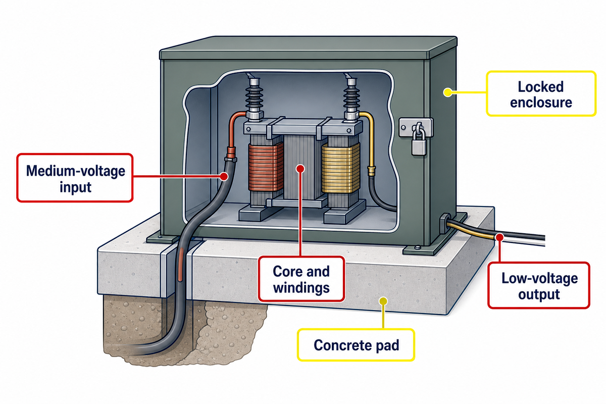
A single-phase pad-mounted transformer is a locked, ground-mounted distribution transformer that receives an underground medium-voltage circuit and supplies a low-voltage single-phase load. Its ratings, terminal arrangement, protection, enclosure, ownership, and site interfaces must match the serving system. The equipment name alone does not establish a project specification.
The published scope of IEEE C57.12.38-2025 covers specified characteristics and safety requirements for a bounded family of single-phase, 60 Hz, liquid-filled, self-cooled, pad-mounted compartmental transformers. Its public scope page includes units rated 250 kVA and smaller, with high voltage no greater than 34.5 kV GrdY/19.92 kV and low voltage no greater than 480/240 V. Those are the standard’s scope limits, not a claim that Talite offers every value in that range. Check the IEEE C57.12.38-2025 scope.
This article’s lifecycle method can still organize a project that falls outside those stated limits, but the C57.12.38 citation cannot be used as evidence that an out-of-scope design is covered.
In plain electrical power terms, this is usually a step-down power supply function: primary power enters at medium voltage and the transformer supplies a lower-voltage service. “HV,” “34.5kV,” and “35 kV” are common search or drawing labels, but the spaces, abbreviations, and nearby numbers do not establish a voltage class or available design. Use the exact nameplate and system notation.
- Utility circuit: an underground medium-voltage feeder reaches the transformer location.
- Primary interface: cables, terminals or separable connectors, and the circuit arrangement meet the approved network design.
- Electromagnetic conversion: the core and windings change the voltage relationship while keeping the same frequency.
- Secondary interface: the lower-voltage output connects to the service conductors and the downstream distribution system.
- Load: the building, site, or defined load area receives single-phase power through its own protection and distribution equipment.
Pad-mounted and pole-mounted are installation routes, not quality grades. If the project is comparing underground and overhead installation methods, discuss the single-phase pole-mounted transformer route separately in that context. A more general pad-mounted distribution transformer product family discusses related equipment, but not the current project’s phase, rating, or interface.
Follow the Energy Path Before Comparing Components
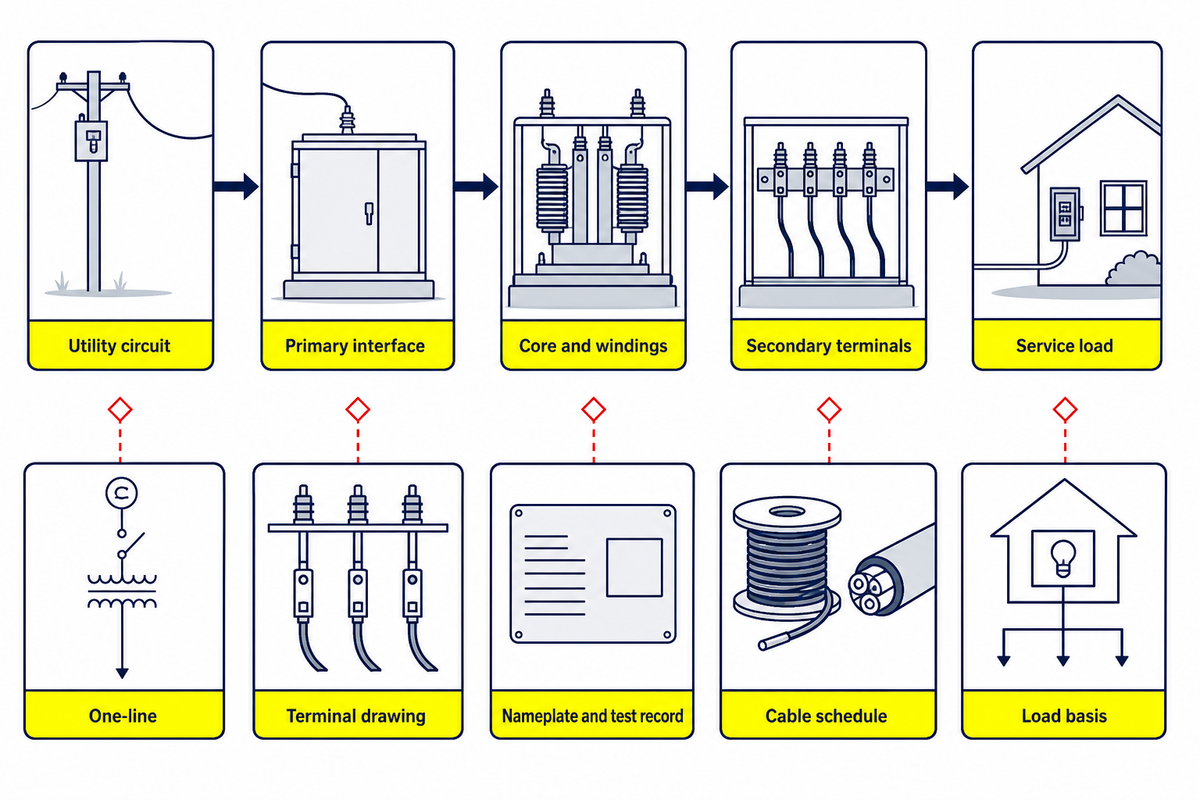
A component list is useful only when each item connects to a function and a verification record. The table below is a document-review map. It does not specify a particular accessory package, because the standard scope, utility arrangement, project drawings, and supplier design may assign different requirements.
Engineers often use coil as shorthand for a winding, but a transformer design is verified as an assembled core-and-winding and insulation system, not by one word. That boundary also applies to oil-filled construction, power cables, a current-limiting fuse, switchgear, and no-load records: each can be relevant, yet none is guaranteed by the product-family label. Electrical and mechanical evidence must come from the applicable design and purchase documents.
| Part | System function | Verification evidence | Do not infer |
|---|---|---|---|
| Core and windings | Establish the electromagnetic voltage relationship | Approved design data, nameplate, and factory records | That a familiar kVA proves the voltage or thermal fit |
| Insulating liquid and tank | Provide insulation, heat-transfer, containment, and mechanical housing functions | Supplier data, nameplate, shipment inspection, and fluid records where required | Fluid type or condition from enclosure appearance |
| Primary bushings or terminals | Connect the incoming medium-voltage circuit | Utility one-line, approved drawing, interface schedule, and cable data | Circuit topology from a product photograph |
| Secondary terminals | Connect the lower-voltage service conductors | Voltage schedule, conductor design, terminal drawing, and torque record | Conductor quantity or terminal capacity from output voltage alone |
| Fusing and protection | Coordinate fault and abnormal-current response within the system design | Protection study, utility criteria, approved device schedule, and settings | A universal fuse arrangement for every utility |
| Surge arresters | Limit specified overvoltage exposure when included in the design | Insulation-coordination basis, utility standard, and supplier drawing | Presence, rating, or location from the transformer family name |
| Grounding points | Provide designated bonding and grounding interfaces | Grounding design, utility detail, site inspection, and test record | That a visible lug proves the complete grounding system |
| Nameplate | Identify the manufactured unit and declared ratings | Purchase record, approved drawing, serial record, and field photo | That identity alone closes site, cable, and utility acceptance |
| Locked enclosure | Restrict access and protect the interfaces within its stated design scope | Enclosure standard, supplier drawing, coating record, and site inspection | Permission for an unqualified person to enter the compartment |
Accessory evidence matters because requirements do not all come from IEEE C57.12.38 itself. Its public scope explicitly excludes requirements for accessory devices from the standard’s stated coverage. Projects should therefore name the drawing, local service rule, contract section, or separate standard that governs each arrester or other accessory instead of using “meets IEEE” as an all-purpose answer.
Separate Feed Arrangement From Interface Style
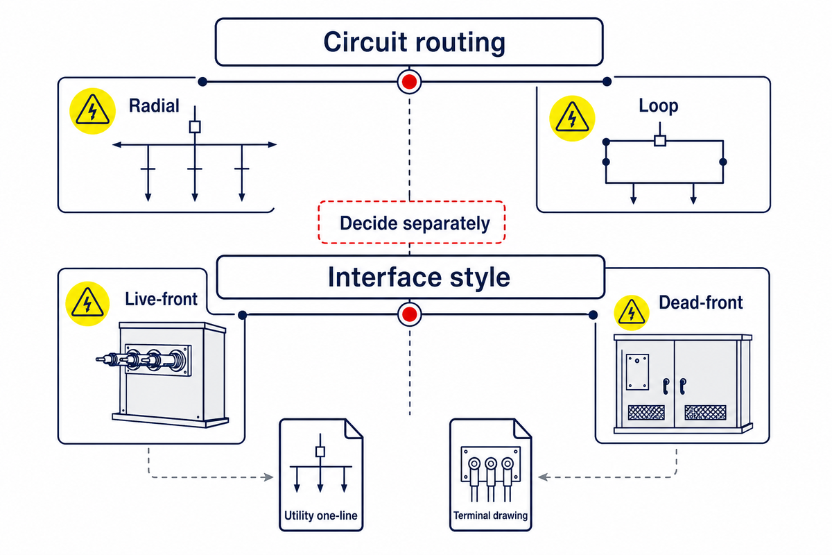
Radial and loop feed describe circuit routing and primary connection configuration. Live-front versus dead-front answers an interface-style question. The terms influence one another, but they are not synonyms and should occupy separate fields in the project basis.
| Decision axis | Question it answers | Evidence to request | What the label cannot prove |
|---|---|---|---|
| Radial arrangement | How the transformer sits on a circuit path with one source-side route | Utility one-line, primary-cable schedule, terminal drawing, operating rules | Connector style, switching permission, protection settings, or restoration procedure |
| Loop arrangement | How an in-and-out circuit route and associated terminals are arranged | Utility one-line, normal-open point, cable identities, operating practice | That both sides are energized, or that the equipment itself authorizes switching |
| Live-front interface | How energized primary parts may be exposed within the authorized work arrangement | Interface drawing, barriers, utility practice, qualified-work procedure | Feed topology or permission for general access |
| Dead-front interface | How separable insulated high-voltage connectors and shielded interfaces are arranged | Connector ratings, bushing-interface data, cable system, accessory schedule | A de-energized condition, feed topology, or a universal accessory set |
IEEE C57.12.38-2025’s public scope includes radial feed and loop arrangements of connectors, bushings, and terminals, which supports keeping the circuit field explicit. Do not import “three bushing versus six bushing” shortcuts from three-phase articles into a single-phase review. Ask for the single-line diagram and the actual terminal drawing.
Configuration rule: The one-line diagram proves the intended circuit route; the approved interface drawing proves how the cable connects; the operating procedure defines who may switch or access it. No one label replaces all three records.
If the route itself is still open, use Talite’s equipment-path discussion guide. This article keeps the vocabulary distinct but does not reproduce that tool’s decision tree.
Use the 3-Track Pad-Mount Lifecycle Atlas
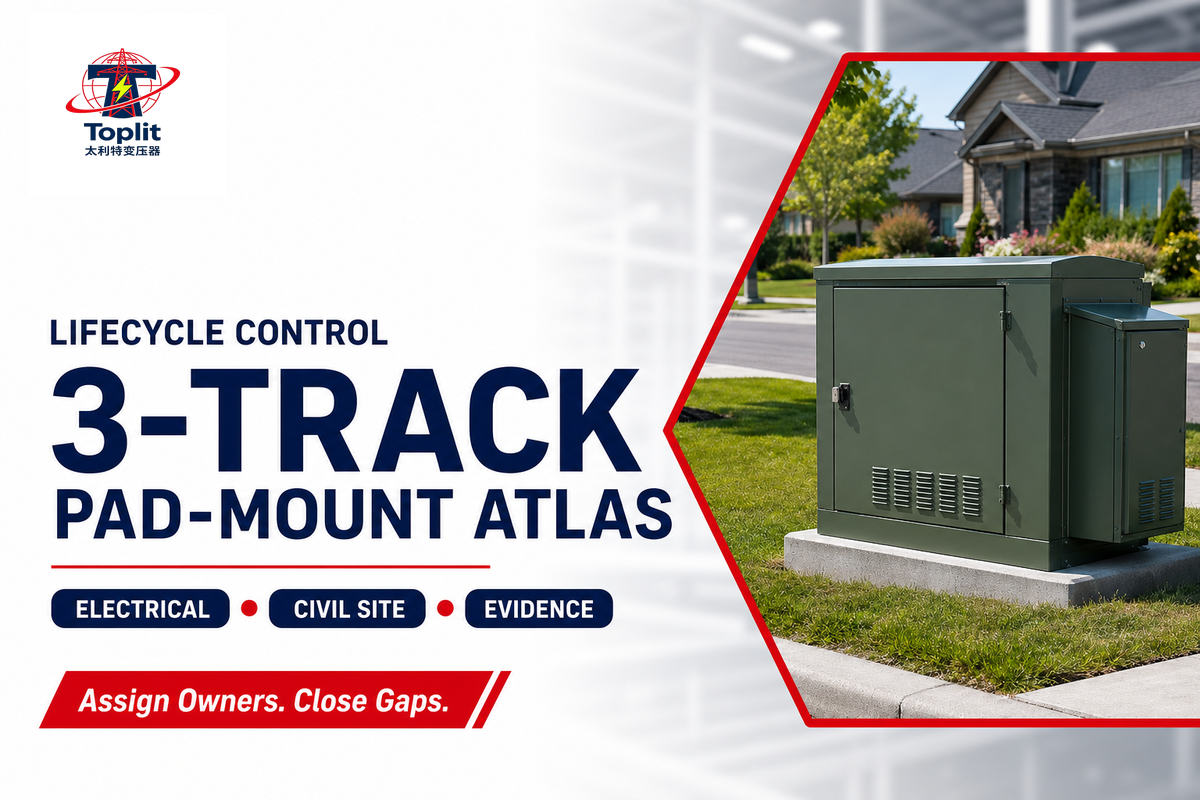
With the feed arrangement and interface style recorded as separate fields, the next hidden bottleneck may not be a missing number. It is an input with no decision owner or governing source. Use the atlas below to mark each row known, owner-confirmed, source-confirmed, or unresolved. An unresolved item is not an automatic rejection; it is a routing instruction.
| Track category | Field | Decision owner | Governing source | If unresolved |
|---|---|---|---|---|
| Electrical | Load basis and duty | Owner + engineer | Load schedule and design criteria | Issue a load-data request |
| Electrical | Primary and secondary voltage | Utility + engineer | Utility service letter and one-line | Stop rating comparison |
| Electrical | Feed and interface axes | Utility + engineer | One-line and interface schedule | Request both records |
| Electrical | Protection and grounding basis | Engineer + utility | Study, utility standard, grounding design | Create a design hold point |
| Civil/site | Pad geometry and loading | Civil engineer + utility | Approved equipment drawing and local detail | Do not pour the pad |
| Civil/site | Conduits and cable route | Utility + electrical contractor | Duct-bank drawing and pulling plan | Coordinate bends and entries |
| Civil/site | Drainage and flood exposure | Civil engineer + owner | Grading, flood, and stormwater documents | Reassess location/elevation |
| Civil/site | Access and impact protection | Owner + utility | Site plan, utility clearance rules, traffic plan | Resolve access before delivery |
| Evidence/ownership | Product and enclosure scope | Engineer + supplier | Applicable standards and specification | Issue a scope clarification |
| Evidence/ownership | Manufacturing and factory records | Supplier + procurement | Purchase order and approved data | Hold shipment acceptance |
| Evidence/ownership | Site inspection and test pack | Contractors + commissioning lead | Inspection and test plan | Open an evidence action |
| Evidence/ownership | Utility release and project acceptance | Utility + owner | Release notice, acceptance record, deviation log | Do not declare ready |
The atlas converts public standards and utility information into a buyer action; it is not a design form. One reviewed municipal utility manual, for example, separates developer and power-company responsibilities and publishes its own pad, conduit, grounding, access, and barrier details. That proves role and document variability, not that its dated dimensions apply to another service territory. See the Springville utility manual example.
Size the Load Without Treating Catalog kVA as Design Approval
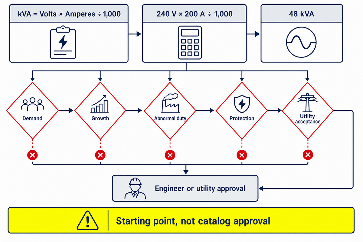
For single-phase loads, a preliminary apparent-power calculation provides a transparent starting point, not a final transformer selection. Use the documented voltage and current below, then test demand, growth, abnormal duty, voltage, protection, and utility acceptance before an engineer or network owner approves a catalog kVA rating.
Single-phase planning formula
kVA = volts × amperes ÷ 1,000
Hypothetical example: 240 V × 200 A ÷ 1,000 = 48 kVA.
Both the formula and 48 kVA arithmetic can be independently reproduced; a commercial kVA calculator provides a cross-check. That result is neither a standard transformer size nor permission to order one. It does not yet describe demand, load profile, motor starting, temperature, growth, abnormal operating cases, primary voltage, secondary arrangement, protection, efficiency classification, provider rules, or the engineer’s design basis.
Published kVA ratings become useful only after the calculation, voltage, duty, configuration, and approval basis agree. A list of kVA ratings is therefore an output of supplier and engineering review, not a substitute for the load schedule.
| Input | Illustrative value | Status | Real-project source |
|---|---|---|---|
| Service voltage | 240 V | Hypothetical | Utility service letter and one-line |
| Planning current | 200 A | Hypothetical | Load schedule and demand study |
| Arithmetic result | 48 kVA | Calculated | Checked calculation sheet |
| Demand/diversity factor | Not assumed | Unresolved | Engineer-accepted study and utility criteria |
| Growth allowance | Scenario only | Owner decision | Approved expansion forecast |
Test the arithmetic before discussing a rating. At 240 V and 150 A, the same formula gives 36 kVA. At 240 V and 250 A, it gives 60 kVA. At 208 V and 200 A, it gives 41.6 kVA. These three sensitivity rows show how an input change moves the planning result; they still do not establish a standard size or acceptable loading practice.
| Scenario | Voltage | Current | Calculated apparent power | Decision lesson |
|---|---|---|---|---|
| A | 120 V | 100 A | 12 kVA | Arithmetic only; confirm the actual service arrangement |
| B | 208 V | 100 A | 20.8 kVA | Voltage still needs utility confirmation |
| C | 208 V | 200 A | 41.6 kVA | Doubling current doubles the arithmetic result |
| D | 240 V | 100 A | 24 kVA | Connected current is not a demand factor |
| E | 240 V | 150 A | 36 kVA | Load profile remains unresolved |
| F | 240 V | 200 A | 48 kVA | Base example, not a catalog selection |
| G | 240 V | 250 A | 60 kVA | Growth and duty still need justification |
| H | 480 V | 100 A | 48 kVA | Same kVA does not mean the same voltage system |
Every row uses kVA = V × A ÷ 1,000. These scenarios are mathematical comparisons, not recommended services, standard ratings, or loading limits.
- Build a load schedule with units and operating cases.
- Separate connected load from justified demand or diversity assumptions.
- Calculate the base case and at least two growth or duty scenarios.
- Confirm primary and secondary voltage, phase, circuit arrangement, protection, and provider criteria.
- Ask the responsible engineer and network owner to confirm the final rating and configuration.
Do not copy a Talite three-phase or oil-immersed product range into this calculation. The commercial target page provides a project-review destination, not a verified public model table for the single-phase target family.
Coordinate the Pad, Cables, Grounding, Access, and Drainage
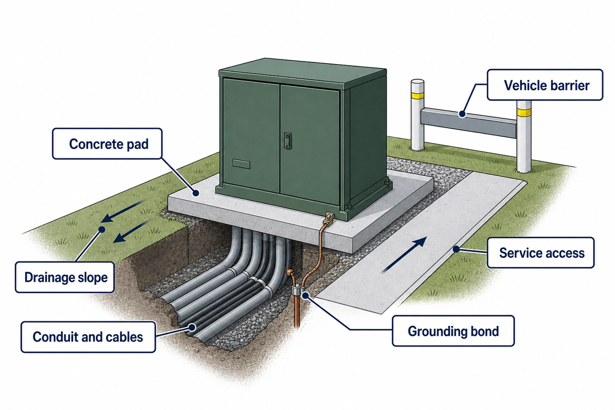
Once the load-basis arithmetic and rating boundary are documented, site coordination works best as a responsibility ledger because a technically correct item can still arrive too early, use the wrong drawing revision, or wait on another party’s release. The six role groups below are a starting structure. Replace them with the names and contract assignments on the actual project.
| Interface | Responsible role | Governing document | Needed by | Hold point / evidence |
|---|---|---|---|---|
| Service voltage and point | Utility/owner | Service letter and one-line | Before equipment data approval | Written utility confirmation |
| Electrical design basis | Engineer | Load, protection, grounding studies | Before supplier review | Approved calculations |
| Equipment footprint and mass | Supplier | Approved general arrangement | Before final foundation design | Released drawing revision |
| Foundation and anchors | Civil contractor | Civil design + utility detail | Before delivery | Survey, strength, level, dimensions |
| Conduit entries and bends | Civil + electrical contractors | Duct-bank and cable-pull drawings | Before concrete placement | Joint pre-pour inspection |
| Primary cable supply/pull | Utility or electrical contractor | Ownership matrix and cable schedule | Before termination | Cable identity and test record |
| Secondary conductors | Electrical contractor | Conductor and terminal schedules | Before connection | Phase/neutral identity and termination record |
| Grounding and bonding | Engineer + electrical contractor | Grounding design and utility rules | Before energization inspection | Inspection and test record |
| Grading, drainage, flood exposure | Owner + civil engineer | Site grading and flood documents | Before location approval | Elevation/location acceptance |
| Access and vehicle protection | Owner + utility | Site/traffic plan and utility criteria | Before final site release | Clear access and barrier inspection |
| Factory data and shipment condition | Supplier + procurement | Purchase order, approved data, shipping plan | Before receipt acceptance | Serial, nameplate, condition, record pack |
| Release and handover | Commissioning/operations + utility | Inspection/test plan and utility process | Before energization | Signed release and open-item disposition |
Do not copy a generic pad dimension or clearance from a search result. That reviewed Springville document is useful because it shows how one power company allocates work and publishes detailed site requirements, but it is a dated local example. Current provider rules, the approved equipment drawing, civil design, site conditions, and the contract control the real project.
IEEE C57.12.28-2023 has a narrower role: its public scope addresses enclosure and coating integrity for qualifying above-grade pad-mounted equipment over 600 V that may be exposed to the public. It does not decide the pad geometry, drainage, cable route, network ownership, or full purchase specification. Review the C57.12.28-2023 scope.
Match Each Standard or Project Document to Its Decision
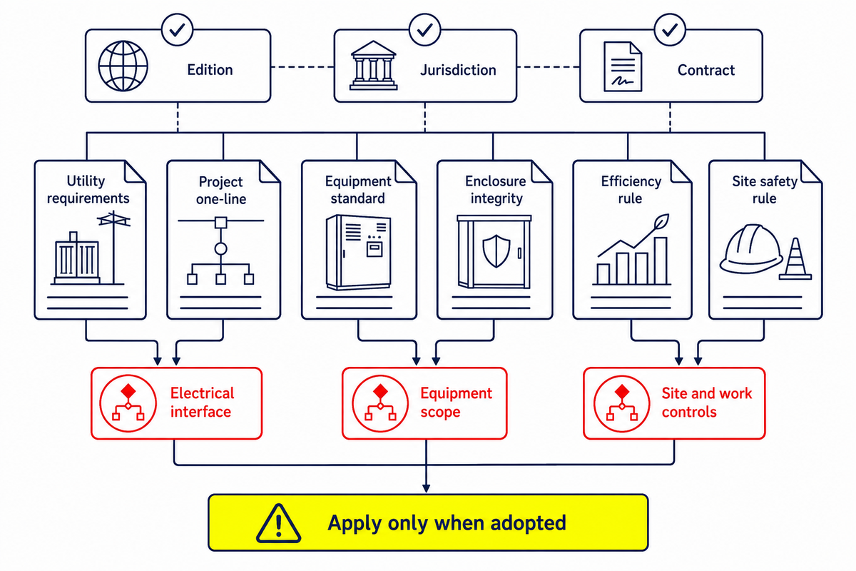
A standards list becomes useful only when it states what each document governs, and what it does not. Edition, jurisdiction, equipment class, manufacturing date, utility adoption, contract hierarchy, and project-specific deviations can all change the answer.
Do not turn acronyms into a compliance bundle. ANSI, NEMA, RUS, UL, IEC, IEEE Std references, C57.12.00, and other industry standards may appear in specifications, but only the applicable ANSI and IEEE requirements, or other adopted requirements, belong in the final scope. Serving-jurisdiction rules and the contract must identify which ones apply. Terms such as fire-resistant, fire safety, energy efficiency, renewable energy, and superior dielectric performance also need a defined test, rating, or source before they become acceptance criteria.
| Document | Status at research time | Decision it informs | Limit |
|---|---|---|---|
| IEEE C57.12.38-2025 | Published active edition | Specified characteristics and safety requirements within its single-phase pad-mounted scope | Not a claim of model availability; accessory requirements sit outside its stated scope |
| PC57.12.38 | Active revision project; PAR approved May 14, 2026 | Signals a future superseding project | Not yet a published replacement edition |
| IEEE C57.12.28-2023 | Published active edition | Enclosure and coating integrity within its above-grade public-exposure scope | Not a complete civil, cable, or purchase specification |
| 10 CFR Part 431, Subpart K | Current U.S. regulation | Covered equipment definitions, test procedures, and efficiency tables | Apply the correct class and manufacturing-date tier; do not reduce it to one universal number |
| June 15, 2026 DOE notice | Request for information | Collects information about the April 2024 rule, 2029 compliance, manufacturing, and supply constraints | It is not a final amendment |
| Serving-utility requirements | Local and revision-dependent | Service arrangement, ownership, accepted interfaces, site details, and release process | Another utility’s manual is not transferable approval |
| Project specification, drawings, and contract | Project-specific | Selected requirements, responsibilities, submittals, tests, and acceptance | Conflicts need formal clarification; do not choose a hierarchy by guess |
IEEE lists C57.12.38-2025 as the published edition. It separately lists PC57.12.38 as an Active PAR approved May 14, 2026 that is intended to supersede it. A revision project is not a published replacement.
Unit discipline: 60 Hz and 250 kVA belong to the stated C57.12.38 scope; 600 V belongs to the C57.12.28 enclosure-scope boundary; 50 V appears in the OSHA qualified-work boundary. These four source-scoped values answer different questions and aren’t a combined product recommendation.
For covered U.S. distribution transformers, the current eCFR text attaches efficiency tiers to manufacturing dates. For equipment manufactured on or after April 23, 2029, it provides separate liquid-immersed tables for units that are not submersible and for submersible distribution transformers. DOE’s June 15, 2026 document is a request for information, not a final change to that rule.
Use Talite’s standards-scope triage when a project needs a deeper document-by-document check. That tool owns the triage logic; this guide owns the basic scope map.
Reconcile Evidence Before Energization
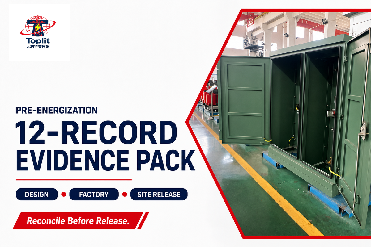
After each standard or project document has been matched to a decision, “factory tested” does not mean “site ready.” Factory evidence, shipment condition, installed interfaces, utility release, project acceptance, and unresolved deviations are separate evidence classes. Each release pack should let a reviewer trace the manufactured unit to the approved design and the installed system without assuming that one record covers another stage.
| Record | Stage | Owner | Acceptance source | Open-item field |
|---|---|---|---|---|
| Approved general arrangement | Design | Engineer/supplier | Submittal procedure | Revision and deviations |
| Nameplate and serial match | Receipt | Procurement/site | Purchase order and approved data | Mismatch disposition |
| Factory test records | Manufacture | Supplier | Specification and approved plan | Exceptions and approvals |
| Shipment/receipt condition | Logistics | Carrier/site/supplier | Shipping and receiving plan | Damage or fluid concern |
| Pad survey and condition | Civil | Civil contractor | Approved civil/utility detail | Level, strength, entry conflict |
| Primary cable identity/test | Installation | Utility/contractor | Cable and utility procedures | Failed or incomplete result |
| Secondary conductor/termination record | Installation | Electrical contractor | Approved design and procedure | Identity, torque, or damage issue |
| Grounding/bonding inspection | Installation | Contractor/engineer | Grounding design and utility rule | Missing connection or result |
| Protection settings/coordination acceptance | Commissioning | Engineer/utility | Protection study and utility criteria | Unapproved setting |
| Enclosure, access, drainage inspection | Site release | Owner/utility | Site and utility requirements | Impact, access, water, lock issue |
| Utility release | Energization | Utility | Utility acceptance process | Conditions of release |
| Project acceptance and deviation log | Handover | Owner/commissioning lead | Contract and turnover plan | Owner, due date, operating constraint |
Use one file index with record name, revision, date, owner, acceptance source, status, and deviation reference. Blank fields should remain visibly unresolved; replacing one with “N/A” without an approved reason hides a coordination risk.
Field-testing guidance also needs scope control. IEEE C57.152-2025 is a broader guide for diagnostic field testing of liquid-immersed power transformers and regulators. Its public scope says several test types should be interpreted together and manufacturer acceptance criteria consulted. It is not established here as a product-specific single-phase distribution-transformer acceptance standard. Read the IEEE C57.152-2025 scope.
Read Common Problems Without Entering the Compartment
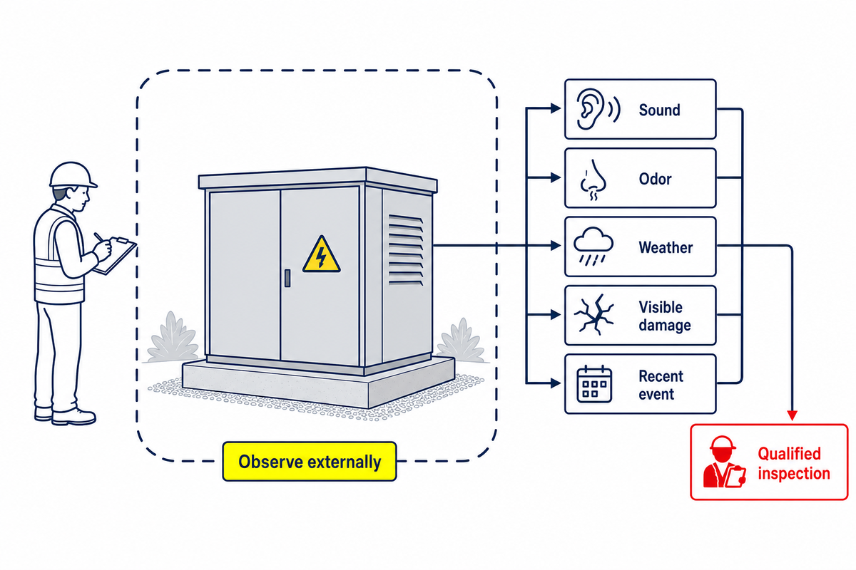
After the evidence pack is reconciled, observation and root-cause determination remain different tasks. From a safe external position, a site representative can record a condition, time, location, sound, odor, weather, visible damage, and recent event. That record can justify isolation or qualified inspection. It cannot prove one internal failure mode.
For covered electric-power work, OSHA 1910.269 restricts work around unguarded energized parts at 50 V or more to qualified employees and requires lines or equipment to be treated as energized until deenergized under the applicable procedure. It also addresses the energized status of transformer cases unless grounding is determined. This article is not an operating or deenergization procedure. Review OSHA 1910.269.
| External signal | Safe record from outside | Escalation trigger | Do not |
|---|---|---|---|
| Visible liquid or staining | Location, spread, color, time, weather, photo from boundary | Active leak, spreading liquid, environmental exposure, or unknown fluid history | Touch, sample, clean, or open the enclosure |
| New or accelerating corrosion | Panel/location, coating loss, drainage conditions, dated image | Perforation, door/lock impairment, rapid progression | Scrape, paint, or test the surface on energized equipment |
| Unusual or changed sound | Time, duration, load/event context, safe audio if permitted | Sudden change, sharp intermittent sound, or accompanying odor/heat evidence | Assign an internal cause from sound alone |
| Unusual odor or smoke | Wind direction, visible source area, time, nearby activities | Smoke, burning odor, fire evidence, or worsening condition | Approach to identify the source |
| Heat discoloration or damaged coating | External location and dated photo | New discoloration, deformation, odor, or protective operation | Touch the enclosure or use unapproved test equipment |
| Damaged lock, door, or panel | Damage point, access condition, impact evidence, photo | Compromised security, exposed gap, or public access risk | Push, realign, or enter the compartment |
| Disturbed cable area or soil | Excavation, settlement, animal activity, vehicle event, location | Possible cable-route disturbance or exposed conduit | Probe, dig, or move material near the route |
| Repeated protective operation or outage | Event times, affected loads, weather, upstream/downstream observations | Repeat event, unknown protection status, or abnormal restoration | Reset, switch, or bypass protection without authority |
| Flooding or standing water | Water extent/depth from distance, rainfall/event, drainage path | Water reaching equipment or cable interface area | Enter water or assume the enclosure is submersible |
| Vehicle or object impact | Impact direction, visible displacement, barrier condition, photo | Any enclosure movement, deformation, leak, or cable-area disturbance | Move the equipment or damaged barrier |
Purpose-built monitoring can support a qualified assessment, but it must be specified and verified. One reviewed patent, for example, describes measurement channels, thresholds, and overload notification logic. That is evidence that cause determination may require instrumentation; it is not evidence that ordinary pad-mounted equipment contains the patented system.
Conditional legacy note: If an existing transformer has an unknown fluid history or records indicating a regulated PCB classification, the owner should preserve the scene and obtain qualified environmental and network-owner guidance. EPA describes registration obligations for covered PCB transformers and points to 40 CFR Part 761 for disposal and storage rules. This does not imply that modern Talite equipment contains PCBs. See EPA’s PCB transformer disposal and storage guidance.
Move From Education to a Supplier-Specific Review
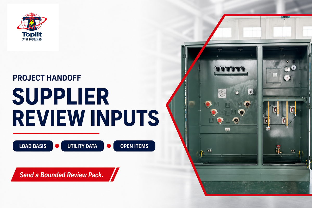
After an external condition has been recorded and escalated, supplier-specific review becomes productive when the project team can send a bounded, source-linked basis instead of asking the supplier to fill every blank. The handoff should identify verified inputs, unresolved assumptions, their decision owners, and the documents that govern each open item. Before the handoff, collect:
- the verified load basis, operating cases, and growth assumptions;
- primary and secondary voltage requirements and the service-provider one-line;
- the separate feed-arrangement and interface-style decisions, with owners;
- applicable service-provider requirements, standards scope, and manufacturing-date jurisdiction;
- pad, conduit, cable, grounding, drainage, access, and impact-protection boundaries;
- factory, site, utility-release, and project-acceptance evidence expectations;
- a visible list of unresolved assumptions and who will close them.
Talite Transformer Co., Ltd. describes more than three decades in the power-equipment sector, with R&D, production, and sales operations in the Hai’an Economic and Technological Development Zone of Nantong, Jiangsu Province. For models, project fit, availability, pricing, lead time, and supplier review, continue to Talite’s single phase pad mounted transformer solutions and project review.
That commercial handoff is where project-specific power solutions, transformer design options, sound levels, and any customizable features should be confirmed. This guide does not claim those attributes for an unreviewed unit.
If the project basis is already assembled, use the Talite 8-input RFQ completeness checker to test whether key fields are still missing. That checker owns input completeness; this guide owns the lifecycle explanation.
Have a load schedule and service-provider basis?
Share the known electrical, site, and evidence fields, including each unresolved owner or source. Talite can identify supplier-side questions and documentation gaps, while your network owner and responsible engineer retain authority for service acceptance, protection, site approval, and the final equipment decision.
Frequently Asked Questions About Single Phase Pad Mounted Transformers
What is a single-phase pad-mounted transformer?
A single-phase pad-mounted transformer is a ground-level distribution unit that connects to an underground medium-voltage circuit and supplies a lower-voltage single-phase service to a defined load area.
A single-phase pad-mounted transformer is a ground-level distribution unit normally connected to an underground medium-voltage circuit. It changes that supply to a lower-voltage single-phase service for a defined load area. Its locked enclosure, cable interfaces, protection, ratings, and utility ownership rules vary by system, so the equipment name alone does not establish a complete project specification.
What is the purpose of a pad-mounted transformer?
Placed near the served load, a pad-mounted transformer connects to an underground distribution network, but its cables, protection, foundation, grounding, access, and utility interfaces still require coordination.
Its purpose is to place the voltage-conversion point near the served load while connecting to an underground distribution network. A project still has to coordinate primary and secondary voltages, load basis, cable interfaces, protection, foundation, grounding, access, and utility rules. Enclosure location is only one part of the electrical and civil system.
What are common problems with padmount transformers?
Common observable concerns include fluid leakage, corrosion, damaged enclosures, unusual sound or odor, heat evidence, flooding, disturbed cable areas, and repeated protective operation; qualified personnel must determine the cause.
Observable concerns can include fluid leakage, corrosion, damaged locks or enclosure panels, unusual noise or odor, heat evidence, flooding, disturbed cable areas, and repeated protective operation. These signs do not identify one root cause from the outside. Record the condition, maintain the required safety boundary, and notify the utility or qualified owner rather than opening an energized compartment.
Is there such a thing as a single-phase transformer?
Single-phase transformers exist, and pad-mounted versions serve some underground distribution systems; the network architecture, load, voltage, protection, and utility requirements determine whether that route is appropriate.
Yes. Single-phase transformers exist, and pad-mounted versions serve some underground systems. Network architecture and load determine whether that route fits.
How do you size a single-phase pad-mounted transformer?
Sizing starts with a documented load schedule, transparent kVA arithmetic, justified demand, and engineer/utility approval; the 240 V by 200 A worked example yields 48 kVA before project-specific adjustments.
Start with a documented load schedule, calculate apparent power in kVA, apply only justified demand or diversity factors, and test expected growth and abnormal operating cases. Then confirm primary and secondary voltages, feed arrangement, protection, efficiency rules, and the serving utility’s standard. This result is a planning basis; the responsible engineer and utility must approve the final rating and configuration.
What is the difference between radial and loop feed pad-mounted transformers?
Radial feed uses one source-side circuit route, while loop feed uses an in-and-out route that may support different isolation or restoration practices; neither label defines the interface style.
Radial feed places the transformer on a circuit path with one source-side route. A loop arrangement uses an in-and-out circuit route that may support different isolation or restoration practices. Those labels do not define connector style, switch positions, operating permission, or protection settings. Confirm the utility one-line, primary terminal drawing, accessory schedule, and operating rules.
Key takeaway
A reviewable pad-mount project is a chain of owned decisions: load basis, circuit and interface, site work, governing documents, installed evidence, release, and safe operating responsibility.
References and Sources
- IEEE C57.12.38-2025: single-phase pad-mounted compartmental transformer scope and status
- IEEE PC57.12.38: active revision project status
- IEEE C57.12.28-2023: pad-mounted equipment enclosure integrity scope
- IEEE C57.152-2025: diagnostic field testing scope for liquid-immersed power transformers and regulators
- eCFR: 10 CFR Part 431, Subpart K, distribution transformers
- U.S. Department of Energy: April 2024 distribution-transformer efficiency rule announcement
- Federal Register: June 15, 2026 distribution-transformer request for information
- OSHA 1910.269: electric power generation, transmission, and distribution
- U.S. EPA: disposal and storage of PCB waste and covered transformer registration
- Springville City: utility-specific underground electrical requirements example
Why we write this
About Toplit Engineering Insights
Toplit publishes transformer field guides from project routing, factory loss-data discipline, and specification review experience. We help engineering and procurement teams compare transformer types, voltage classes, installation constraints, and quotation evidence before they commit to a build.
- Oil-immersed, dry-type and pad-mounted transformer routes
- Loss data, rating schedules and factory evidence
- IEC / IEEE specification and site-input review
- Factory-direct transformer engineering support
Contact Profile
Talk with the Toplit Transformer Team
Company
Toplit Transformer Engineering Team
Toplit Transformer Engineering Team
Factory base
Hai'an, Nantong, Jiangsu, China
Hai'an, Nantong, Jiangsu, China

![Single Phase Pad Mounted Transformer Guide [2026]](https://toplit-transformer.com/wp-content/uploads/2026/08/single-phase-pad-mounted-transformer-guide-featured-1-150x150.png)