Get in touch with Talite Transformer Co., Ltd Company

Compact Substation Project Guide: 7 Readiness Gates

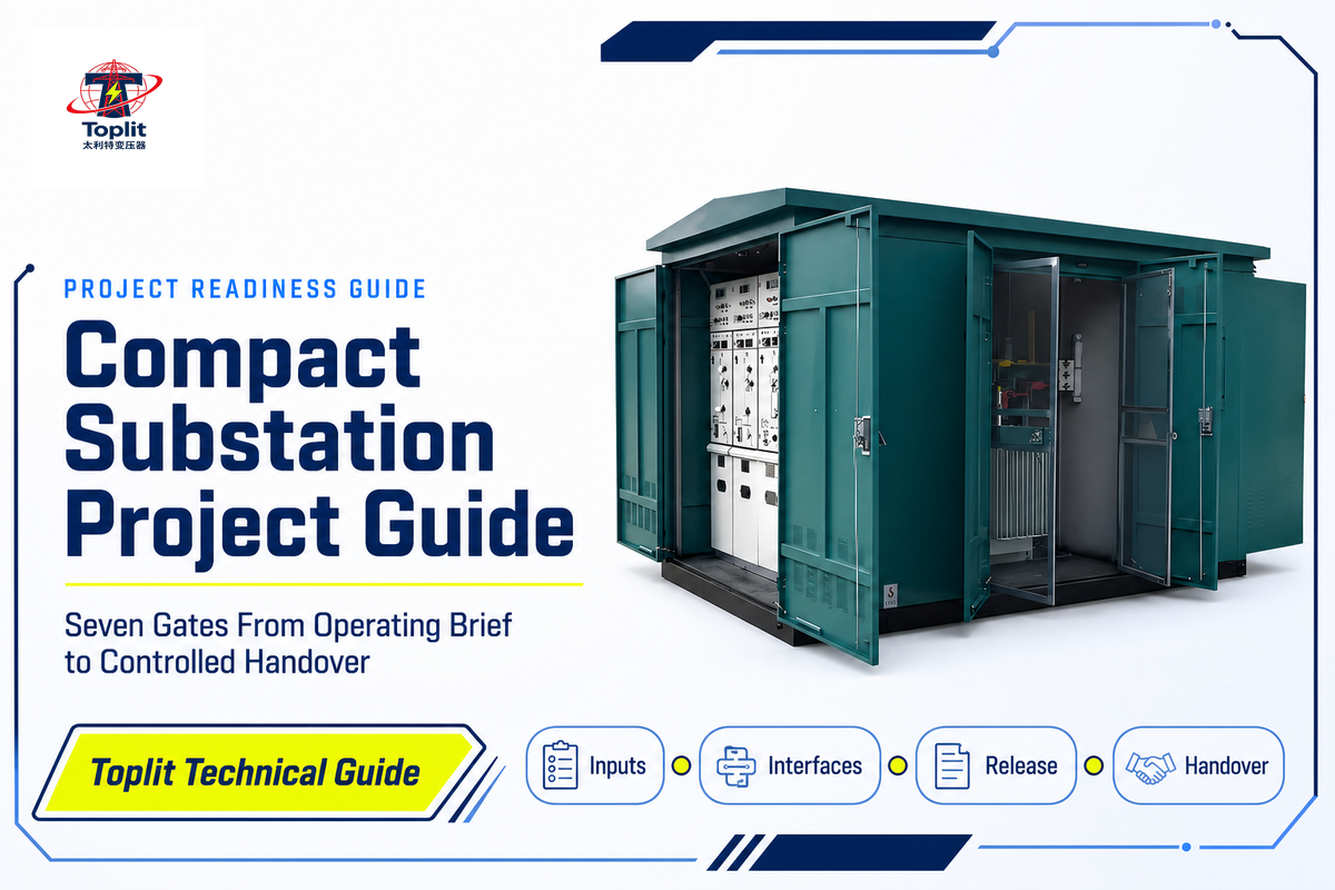
A compact substation project is ready to advance only when every critical input has an owner, an accepted record, and a clear release decision. The enclosure may be compact; the project interfaces are not. Network data, civil works, cable routes, protection decisions, documentation, site readiness, and operating records must converge before release.
This guide translates that work into seven readiness gates. It is written for owners, EPC teams, consultants, utility coordinators, and project engineers moving from an early need to a controlled handover. Readers looking for definitions, components, and classification boundaries can use the separate prefabricated compact substation guide. This page does not select a rating or quote a project from broad assumptions; those are separate tasks.
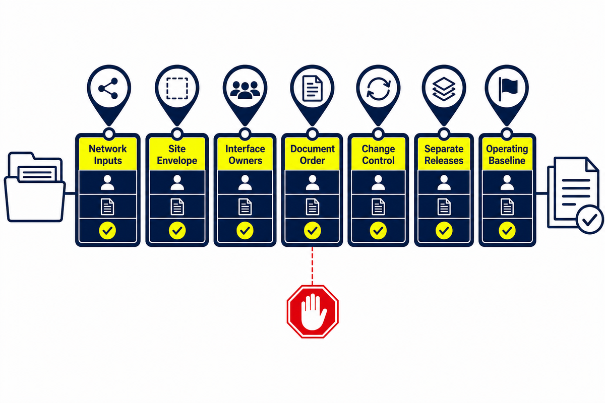
The seven-gate rule
Don’t just ask “Is the equipment ready?” Ask three questions at every gate: Who owns the decision? What record proves it? What must stop the project if it’s missing?
Start With an Operating Brief, Not a Catalogue
The first useful project document is a short operating brief. It describes what the electrical system must achieve before anyone converts that need into equipment details. A strong brief records the intended service, normal and abnormal operating modes, load profile, continuity expectations, growth assumptions, environmental and physical constraints, and the owner’s operating philosophy.
The same discipline applies whether the project supports an industrial distribution network, a solar or wind power project, or an interface near a transmission system. The brief should also identify where the compact substation scope ends and the external low-voltage distribution, high-voltage connection, and plant control responsibilities begin.
This is not a generic transformer-sizing exercise. One peak-load number cannot show starting currents, duty cycles, diversity, harmonics, redundancy expectations, or the consequences of losing a source. Likewise, “future growth” is too vague unless the team identifies what may grow, when it may grow, and which parts of the installation must accommodate it now.
A practical operating-brief checklist
- Service objective: what processes, equipment groups, or building areas will the project support?
- Operating modes: what is normal, planned-outage, standby, emergency, or alternate-source operation?
- Load basis: which load schedule, measured profile, design criterion, or study is the approved baseline?
- Continuity: which processes or loads can be temporarily interrupted and, for these, what is the expected recovery time and sequence?
- Growth: what future increases in load or in services must the facility accommodate within current project scope and timeframe, and what will be left outside?
- Ownership: who accepts responsibility for the brief’s content, and who can approve changes after sign off?
If an element of the operating brief remains provisional, downstream work should be marked provisional too. Treating an assumption as an approved input is one of the fastest ways to produce drawings that look complete but cannot be released.
Gate 1: Freeze Network and Load Inputs
Gate 1 turns the operating requirement into an approved electrical design-input basis. It should cover voltage and frequency, the connection arrangement, load data, available fault-duty basis, grounding approach, protection philosophy, metering requirements, utility constraints, and required study outputs. A preliminary value can support exploration, but it must not silently become a production-release input.
The official scope of IEC 62271-202:2022 covers enclosed AC prefabricated substations above 1 kV and up to and including 52 kV, connected by cable to high-voltage networks, at power frequencies up to and including 60 Hz. It also addresses walk-in and non-walk-in designs. That helps define a product-standard framework. It does not approve a particular project, settle a utility interface, or replace the owner’s specification.
A useful Gate 1 record is an approved electrical-input register. Each row names the input, its source, revision, approver, issue date, and dependent documents. That final field shows the team which calculations, schedules, settings, and drawings need review when an input changes.
| Input | Acceptable record | Gate 1 stop signal |
|---|---|---|
| Network parameters | Owner- or utility-approved data sheet | Values are copied from an old project without confirmation |
| Load basis | Approved load list or study revision | Growth and contingency assumptions are undefined |
| Protection concept | Accepted protection philosophy and study responsibility | Settings owner or coordination boundary is unclear |
Gate 2: Freeze the Site Envelope
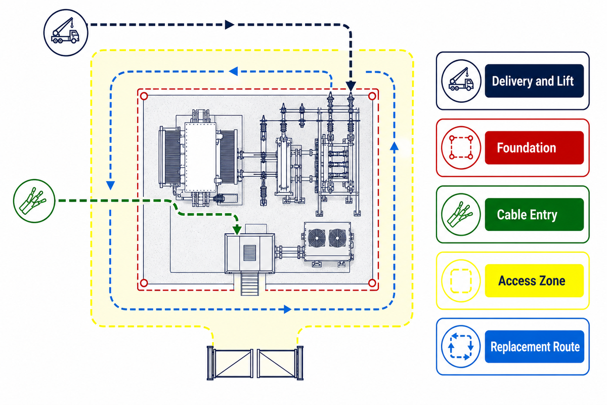
“Compact” describes the assembled solution, not an absence of site work. The project still needs a foundation interface, transport route, lifting approach, cable-entry zones, drainage strategy, ventilation clearances, operating access, maintenance access, and a credible replacement route. Fire, noise, flood, contamination, altitude, temperature, public-access, and adjacent-asset constraints may also change the accepted arrangement.
In U.S. construction contexts, OSHA 1926.966 requires sufficient access and working space around substation equipment for ready and safe operation and maintenance. That rule is jurisdiction-specific, but it shows why access cannot be reduced to an equipment footprint.
Freeze these interfaces as one coordinated site envelope. A footprint drawing alone is not enough. It may indicate the position of the unit with no concept of whether or not the delivery vehicle can turn, whether or not the cranes can reach the site, whether or not the cables will bend into the terminations, or whether a future transformer can move off the site.
The Western Power Distribution Substation Plant Manual is a useful example of why project teams should work from the applicable network’s approved installation information and arrangement drawings. It is not a universal template for other networks, but it demonstrates the relationship between approved arrangements and local constraints.
Review the route, use, and replacement cases together
A site-envelope review should follow the equipment through its life. Can it arrive and be positioned? Can cables and external systems connect without clashes? Can operators work around it? Can maintenance take place within the controlled access zone? Can a major component be removed later? A “yes” at installation and a “no” at replacement is not a frozen interface. The separate pad-mounted transformer lifecycle guide shows how access and records follow adjacent ground-mounted equipment through operation and replacement.
Gate 2 release: the owner, civil designer, electrical designer, logistics or installation party, and equipment supplier have accepted a coordinated drawing set with stated assumptions. Stop signal: any party is still using a different site revision, or a critical route is described only as “to be confirmed on site.”
Gate 3: Assign Every Interface to an Owner
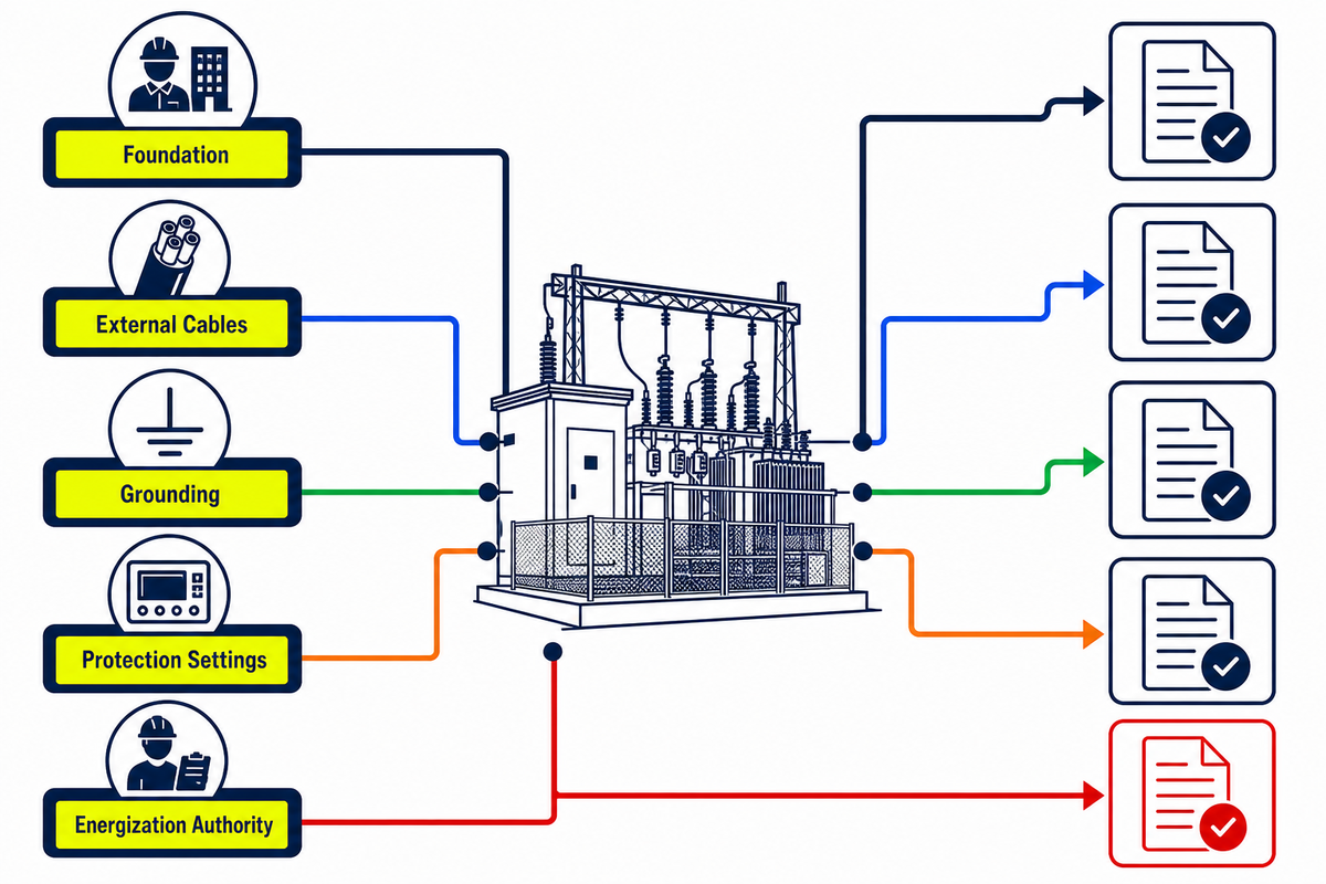
Supply scope and acceptance responsibility are not the same thing. A supplier may provide a connection point, but someone else must design the incoming route, install the external cable, test the completed interface, and accept the record. Gate 3 bridges those gaps with an interface responsibility matrix.
The matrix should identify an accountable owner, not only a list of participants. It should also specify the minimum record required to close the interface. The following example is indicative; the true allocation depends on the contract, utility, jurisdiction, and project organization.
| Interface | Typical accountable party | Supplier input | Closure record |
|---|---|---|---|
| Foundation and fixing points | EPC/civil designer | Loads, dimensions, tolerances | Approved interface drawing and inspection record |
| External cable routes and entries | EPC/electrical designer | Entry zones and termination data | Coordinated route and termination schedule |
| Grounding/earthing integration | Owner or EPC designer | Internal provisions and connection locations | Accepted design and completed test record |
| Protection settings | Named protection authority | Relay data and applicable test evidence | Approved settings file, issue record, and test result |
| Energization authorization | Owner/utility authorized role | Required equipment dossier | Signed release under the project’s rules |
If an interface does not have a named owner or closure record, leave it open. Don’t conceal it within a general note such as “by others.” That phrase allocates work but often does not allocate coordination or acceptance.
Gate 4: Review Documents in Dependency Order
Document control is most effective when reviews follow technical dependencies. A practical sequence begins with the accepted single-line diagram and design basis, then the general arrangement, equipment and cable schedules, civil and cable-interface drawings, control or I/O data, protection settings, test plans, and the handover index.
This is not an inflexible universal sequence; it is a method to prevent downstream documents from being approved against an upstream decision that has yet to be firmed up. For example, a change to the connection arrangement made late in the design process may have implications to the general arrangement, cable schedule, protection study, control interfaces, and test plan. A dependency register makes that impact apparent.
- Identify the controlling inputs. Record the exact revision used by each document.
- Review interfaces, not just individual drawings. Compare dimensions, cable entries, ratings, tags, and terminal references between documents.
- Deal with comments by ownership. Each comment requires a disposition and approver, not just a closed status.
- Retire out-of-date information. Make it difficult for the field team to lay out from an outdated revision.
- Re-open affected records after change. Approval is not enduring when the basis has changed.
Gate 4 release: the project has an accepted dependency sequence, current revision register, resolved critical comments, and a defined production-release set. Stop signal: the disciplines cannot identify the same current single-line diagram, general arrangement, or interface revision.
Gate 5: Control Changes Before Production Release
Compact substation projects concentrate many interfaces into a small physical package. That makes informal late changes especially risky. A change to cable entry, external dimensions, protection data, auxiliary supply, or access can affect work already released by several parties.
Maintain a change record that answers five questions: What changed? Why did it change? Which documents, interfaces, tests, cost, and schedule are affected? Who approves the consequence? Which revised records replace the previous set? If any answer is missing, the change is not controlled.
Gate 5 red flags
- Fault or load data is still provisional while production drawings are marked approved.
- Utility comments remain open but the affected interface is released.
- Cable type, quantity, entry direction, or termination responsibility is unresolved.
- The supplier, civil contractor, and commissioning team hold conflicting revisions.
- A commercial change is logged, but the technical record has not been reissued.
The gate closes when every approved change has an impact review and every affected record has either been reissued or explicitly confirmed unchanged. “We discussed it in a meeting” is context, not configuration control.
Gate 6: Separate Factory Proof, Site Readiness, and Energization
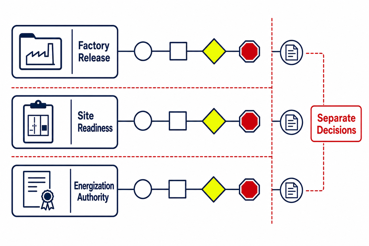
These are three separate release decisions. Conflating them into a single notion—”the substation passed testing”—gives a misleading sense of certainty.
Factory proof
Factory records demonstrate the agreed equipment scope against the applicable inspection and test plan. They may support shipment or another contractual release. They do not prove that the foundation, external cables, grounding system, site controls, utility interface, or operating authorization is complete.
Site readiness
Site readiness confirms that the receiving works, access, external interfaces, installation status, documents, and commissioning plan are ready for the next controlled activity. The open-item status should be explicit: closed, accepted with conditions, or blocking progress.
For the low-voltage installation itself, IEC 60364-6:2016 defines requirements for initial and periodic verification. Its scope is not a substitute for the project’s high-voltage, utility, or energization requirements; it reinforces the distinction between factory evidence and verification of the installed system.
Energization authorization
Energization is governed by the owner’s, utility’s, and jurisdiction’s authorized process. It requires the applicable records and approvals; it is not granted by this guide, a factory report, or a supplier statement. Only qualified and authorized personnel should perform the relevant inspection, testing, switching, and energization work under the site’s approved procedures.
| Release | Primary question | What it does not prove |
|---|---|---|
| Factory release | Does the agreed equipment evidence support the contractual release? | That the site and external systems are ready |
| Site release | Are the installed interfaces and plans ready for controlled commissioning? | That energization is authorized |
| Energization release | Have the authorized parties accepted the required evidence and conditions? | That all operational follow-up is complete |
Gate 7: Hand Over an Operating Baseline
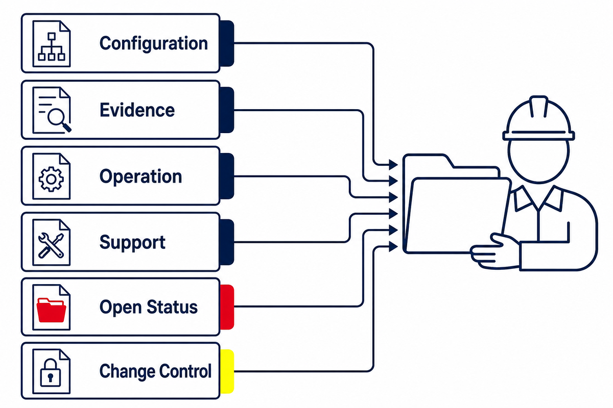
A proper handover leaves operations with a controlled baseline, not a folder of unrelated files. The baseline normally includes accepted as-built drawings, approved settings, applicable test records, OEM manuals, software or configuration versions where relevant, training records, spares information, warranties, open-item status, and the person or function that controls future changes.
Ausgrid NS210 provides an owner-specific example of a controlled project documentation set that includes commissioning plans, as-built information, OEM manuals, software information, and test or commissioning records. Other owners and utilities will use their own requirements, but the broader lesson is transferable: commissioning evidence and operating information need structure, revision control, and an accountable recipient.
The operating baseline handover stack
- Configuration: accepted as-builts, schedules, equipment data, settings, and configuration versions.
- Evidence: applicable inspection, factory, installation, and commissioning records.
- Operation: manuals, limitations, normal operating information, and training records.
- Support: spares, warranties, contacts, and agreed response boundaries.
- Open status: punch-list items, concessions, temporary conditions, owners, and due dates.
- Change control: the custodian of the baseline after handover.
Gate 7 release: the operating custodian accepts the baseline and every remaining condition is visible. Stop signal: the project cannot identify which settings, drawings, or open-item list are current.
Use the Seven-Gate Compact Substation Readiness Board
This board is a coordination tool, not a certification checklist. Mark every gate as Ready, Conditional, or Not Ready. A conditional entry needs the condition, owner, expiry or due date, and the authority that accepted it. An empty entry is not conditional; it is unknown.
| Readiness stage | Accountable owner | Minimum record type | Release decision | Stop signal |
|---|---|---|---|---|
| Entry. Operating brief | Asset owner/project sponsor | Accepted operating brief | Project basis opened | Need, continuity, or growth assumptions are undefined |
| 1. Network and load | Owner/utility design authority | Approved input register | Electrical basis released | Critical data remains provisional |
| 2. Site envelope | EPC/site design authority | Coordinated site/interface set | Layout released | Access, route, or cable clash unresolved |
| 3. Responsibilities | Project manager | Accepted interface matrix | Battery limits accepted | Work is assigned “by others” without closure owner |
| 4. Documents | Lead engineer/document controller | Revision and comment register | Production set released | Disciplines use different controlling revisions |
| 5. Changes | Project change authority | Approved change and impact log | Affected work re-released | Technical consequence is not traced |
| 6. Factory/site/energization | Named authority for each release | Separate signed release records | Next controlled activity authorized | Factory evidence is treated as site approval |
| 7. Operating baseline | Operating custodian | Accepted handover index | Baseline transferred | Current settings or as-builts cannot be identified |
| Exit. Commercial configuration | Owner/procurement lead | Controlled configuration inputs | Supplier discussion authorized | Quotation would depend on unresolved critical assumptions |
Stop Signals That Should Block the Next Gate
A stop signal means the evidence needed for a responsible release is absent, unresolved, or contradictory. The most common signals are:
- The approved load basis cannot be identified.
- Network, fault, grounding, or protection inputs remain provisional.
- Delivery, lifting, installation, relocation, maintenance and repair route is not shown.
- Foundation, cable-entry, or external grounding interfaces conflict across drawings.
- A battery limit has “by others” but there is no responsible closure owner.
- Critical utility or owner comments are still open.
- The production team and site team hold different revisions.
- A late change has no documented cross-discipline impact review.
- Factory completion is being leveraged as a proof of readiness for either site or energization works.
- Operations fail to verify the accepted as-builts, settings, test evidence, or outstanding open items.
The reaction to a stop signal is not always delay. Sometimes the authorized party can accept a clearly defined condition. But that condition still needs an owner, record, boundary, and release authority. Silent assumptions are not an acceptable substitute.
Move From Planning to a Commercial Configuration
Once the operating brief, approved inputs, site envelope, and interface ownership are stable, the project can move into equipment-level configuration without forcing a supplier to price unknowns. Review Toplit’s compact substation engineering and configuration options when the team is ready to discuss ratings, arrangement, applicable requirements, scope boundaries, and quotation inputs. The broader pad-mounted transformer platform keeps adjacent ground-mounted product routes separate.
Jiangsu Toplit Electric Co., Ltd. describes its Hai’an facility as integrating R&D, production, and sales, and lists prefabricated substations, transformers, and supporting switchgear among its product groups. These are company-provided statements; project-specific suitability and compliance still depend on the accepted requirements and evidence for the project.
Have the first four gate records ready?
Share the operating brief, approved network inputs, site interfaces, and responsibility boundary so the technical discussion begins from controlled information.
Frequently Asked Questions
What information should an owner prepare before a compact substation project starts?
Draft an operating brief, an approved load basis, the intended network connection, known utility needs, continuity expectations, site and access restrictions, environmental factors, growth assumptions, and a first-pass responsibility boundary. The detail does not need to contain a finished equipment specification. It does need to clearly delineate approved facts from provisional assumptions. Naming the source, revision, owner, and required approval for each critical input gives the supplier and project team a controlled starting point.
Add a current site drawing, known delivery restrictions, target milestones, and a list of decisions still outstanding from the utility or owner. That allows each participant to price and schedule uncertainty visibly instead of assuming it has been settled as scope.
Who is responsible for the foundation, cables, and grounding?
Responsibility is not universally distributed. Responsibility is contract-dependent, jurisdiction-dependent, and utility rule-dependent. The equipment supplier may supply loads, dimensions, entry zones, and internal connection provisions, while an EPC or owner-appointed designer is responsible for external civil, cable, and grounding works. The project team should record both who does the work and who accepts the finished interface. A note noting “by others” remains incomplete without also naming that responsible party and the closure record.
Does factory testing mean the compact substation is ready to energize?
No. Factory evidence supports the agreed scope of equipment and may support shipment or some other contractual release. Site readiness depends on the receiving works, installation, external cables, grounding, controls, protection information, documentation, and approved commissioning arrangements. Energization depends on the relevant owner, utility, and jurisdictional permissions. These decisions should be separate even though the same team tracks them on a single readiness board.
What is the typical size of a compact substation?
There is no universally correct size. The envelope varies with voltage level, transformer rating, switchgear arrangement, internal access, cable-entry approach, environmental factors, maintenance clearances, and the applicable project requirement. An equipment supplier’s project-specific general arrangement may be used after the key inputs are set. A catalogue dimension can assist initial space planning but should not be used as a released civil interface.
How long does compact substation installation take?
A generic duration can be deceptive. Site preparation, access, civil completion, cable work, utility scheduling, inspection, testing, documentation, and approval are often the dominant constraints as much as equipment location. Create a schedule based on project-specific gate releases and dependencies. Consider broad “weeks instead of months” statements to be marketing hype unless they are substantiated by the defined scope, site realities, resources, and approval process for the individual project.
Is this guide a substitute for the supplier specification or utility approval?
No. This is a project-coordination framework. It helps teams identify missing owners, records, and decisions, but it does not certify equipment, define every technical requirement, replace a contract, or authorize fieldwork or energization. The project must follow the applicable laws, adopted standards, utility rules, owner requirements, supplier documents, and approved procedures. Where those requirements differ from this guide, the project-specific requirements control.
References & Sources
The standards and utility documents linked above are used for bounded examples: the public scope of IEC 62271-202:2022, the relationship between approved network arrangements and installation information in Western Power documentation, and a controlled project-documentation example from Ausgrid. They do not establish one global approval process. Toplit company information is attributed to its own About page. Always verify the current edition and the requirements adopted for the project location.
Why we write this
About Toplit Engineering Insights
Toplit publishes transformer field guides from project routing, factory loss-data discipline, and specification review experience. We help engineering and procurement teams compare transformer types, voltage classes, installation constraints, and quotation evidence before they commit to a build.
- Oil-immersed, dry-type and pad-mounted transformer routes
- Loss data, rating schedules and factory evidence
- IEC / IEEE specification and site-input review
- Factory-direct transformer engineering support
Contact Profile
Talk with the Toplit Transformer Team
Company
Toplit Transformer Engineering Team
Toplit Transformer Engineering Team
Factory base
Hai'an, Nantong, Jiangsu, China
Hai'an, Nantong, Jiangsu, China
![Pad-Mounted Transformer: How It Works [2026 Guide]](https://toplit-transformer.com/wp-content/uploads/2026/08/pad-mounted-transformer-guide-featured-150x150.png)
![Single Phase Pad Mounted Transformer Guide [2026]](https://toplit-transformer.com/wp-content/uploads/2026/08/single-phase-pad-mounted-transformer-guide-featured-1-150x150.png)