Get in touch with Talite Transformer Co., Ltd Company

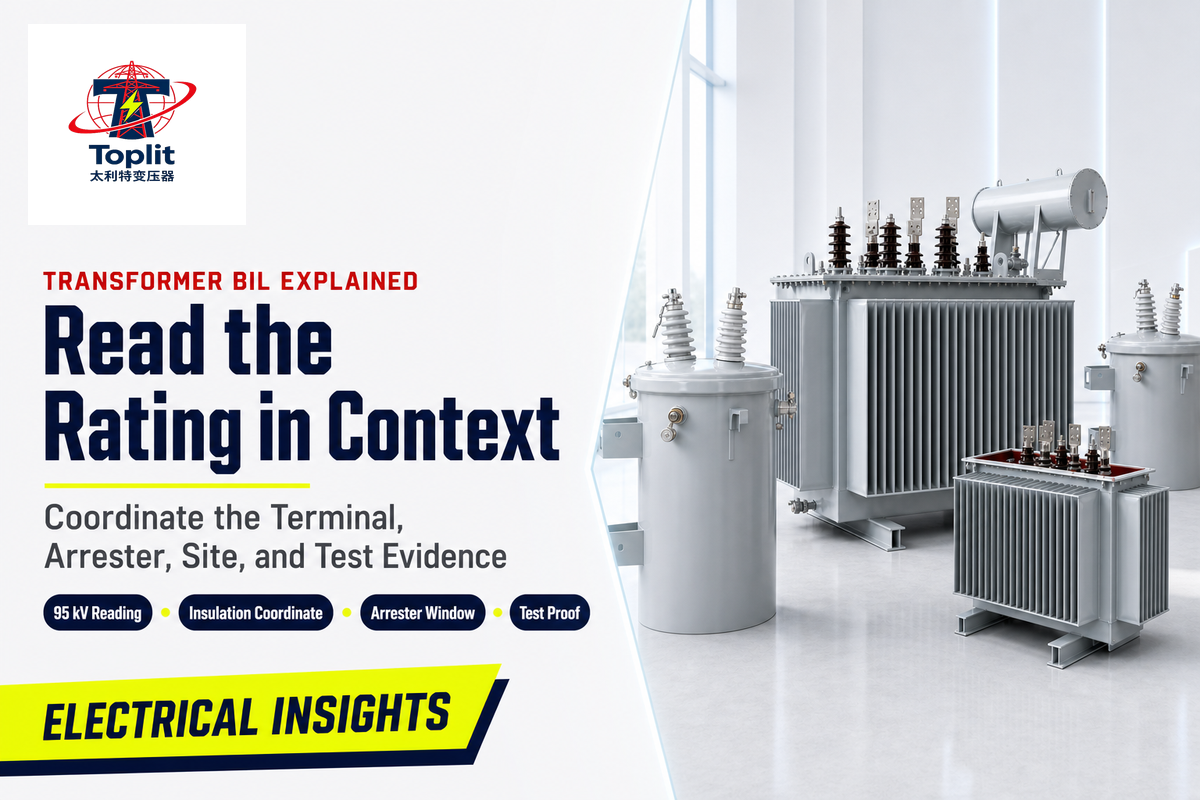
Transformer BIL explained refers to the procurement meaning of Basic Impulse Insulation Level: a peak impulse withstand assigned to a known insulation path for a stated test, not the transformer’s fixed operating voltage. The purchaser’s task is to relate that level to the correct winding or terminal, equipment voltage class, applicable standard, expected overvoltage, surge-arrester duty, site conditions, and test evidence.
The safe reading ruleAn incomplete specification results when the BIL value lacks a standard, terminal, voltage class, coordination basis, or evidence scope.
Generic tables help people recognize a rating but cannot select the value for a live project. IEC 60071-1:2019 frames insulation coordination as a selection procedure, while transformer-specific requirements belong under an applicable transformer standard such as IEC 60076-3:2013+A1:2018 or the relevant IEEE document.
Updated August 2026. Standard editions and project requirements should be checked again when the purchase specification is issued.
Transformer BIL Explained in One Minute
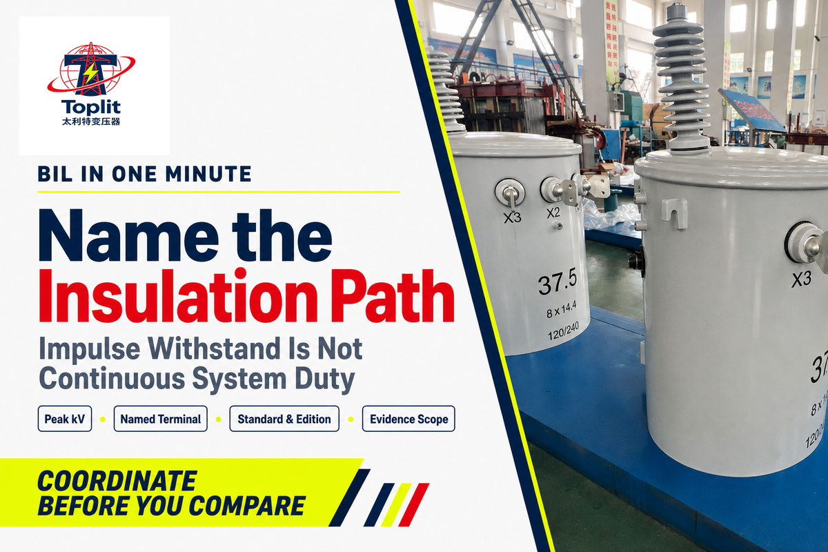
Transformer BIL states how a specified insulation coordinate in electrical equipment is rated against a standardized lightning-impulse test. BIL levels express the dielectric strength assigned to that part of the system insulation in peak kilovolts; they do not describe continuous system duty or guarantee survival under every possible surge.
Rating
Peak impulse withstand in kV
Peak impulse withstand in kV
Event
Defined impulse test, not normal duty
Defined impulse test, not normal duty
Proof
Matched standard, coordinate, and report
Matched standard, coordinate, and report
The phrase “basic insulation level” can tempt a reviewer to treat one number as a whole-transformer property. In practice, different insulation interfaces can have different duties, so a quote that says only “95 kV BIL” leaves the protected coordinate unresolved.
Do
- Identify the winding or terminal.
- Name the governing standard and edition.
- Request evidence tied to the offered design.
Don’t
- Treat BIL as operating voltage.
- Copy a value from another equipment class.
- Assume a label proves every test was run.
The 95 kV (95,000 V) example contains one peak-voltage number; approval still needs the insulation coordinate, equipment class, standard, and test basis.
What Does 95 kV BIL Actually Mean?
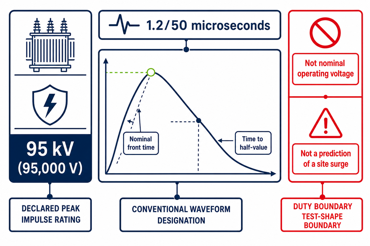
Read a 95 kV BIL entry as a 95 kV (95,000 V) peak lightning-impulse withstand rating for the named insulation path and specified test basis. It is not a 95 kV continuous rating, a universal selection rule, or proof that every terminal has the same impulse level.
95 kVstated peak rating in this example
1.2/50 µsconventional lightning-impulse designation
The standardized lightning impulse waveform is conventionally designated 1.2/50 microseconds, specifying nominal front time and time to half-value. This impulse waveform describes a defined test shape, not a prediction of a site surge; IEC 60060-1:2025 supplies the general terminology while the applicable transformer standard determines the requirement.
Worked reading example
- Read 95 kV as a peak test level, not a continuous voltage.
- Locate the associated winding, terminal, or insulation path.
- Check the equipment voltage class and governing standard.
- Confirm that the cited evidence matches the offered design.
What does 95 kV BIL mean?
A 95 kV (95,000 V) BIL line communicates one declared impulse-withstand voltage rating, not the nominal operating voltage. Selection still depends on the system’s highest voltage for equipment, named terminal, grounding and overvoltage assumptions, environmental conditions, protection arrangement, and applicable standard edition.
Buyer objection: “The number is on the schedule, so why is it not enough?” Because a peak value without its coordinate and test basis cannot be compared consistently across offers.
The 1.2/50 µs label defines a waveform family; 95 kV defines the example crest, while the transformer standard and named terminal define what the entry covers.
BIL Is Not Operating Voltage or Power-Frequency Withstand
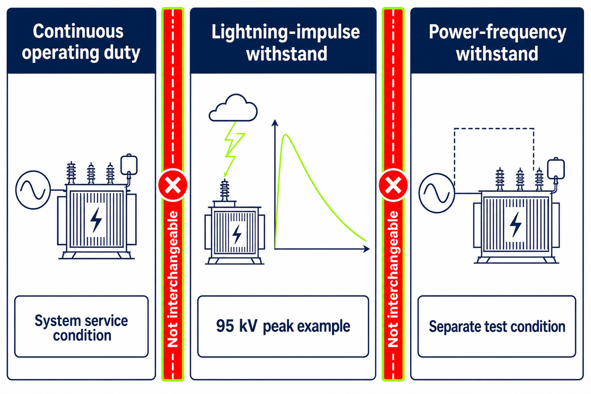
Operating voltage, short-duration power-frequency withstand, and lightning impulse withstand can all be written in kilovolts, yet each describes a different voltage level and electrical duty. Procurement schedules must label the duty, test form, insulation coordinate, and applicable standard instead of relying on the shared kV unit.
| Entry | What it describes | Buyer check |
|---|---|---|
| Operating voltage | Continuous system duty | Rated system and winding basis |
| Power-frequency withstand | Specified alternating-voltage test duty | Exact test label and standard |
| Lightning impulse withstand | Specified impulse test duty | Peak value, coordinate, and test basis |
Adjacent circuit breakers, switchgear assemblies, instrument transformers, and power transformers may be connected equipment in the same electrical system, power system, or voltage distribution network without sharing an equipment standard. The coordination study establishes the relationship among equipment in the system; it does not nullify their part-specific test provisions.
What is the difference between BIL and power-frequency withstand voltage?
BIL refers to lightning-impulse withstand duty. Power-frequency withstand refers to alternating-voltage test duty under the chosen equipment standard, so a clean specification might state “HV terminal: lightning impulse withstand, 95 kV (95,000 V) peak” on one row and “HV terminal: power-frequency withstand, value and test conditions per [standard/edition]” on another.
Common mistake
An unlabeled “kV” column makes three duties look interchangeable. Return the schedule for clarification before comparing bids.
An unlabeled “kV” column makes three duties look interchangeable. Return the schedule for clarification before comparing bids.
One 95 kV peak impulse entry cannot substitute for the separate operating-voltage and power-frequency fields in a transformer specification.
How BIL Fits Into Insulation Coordination
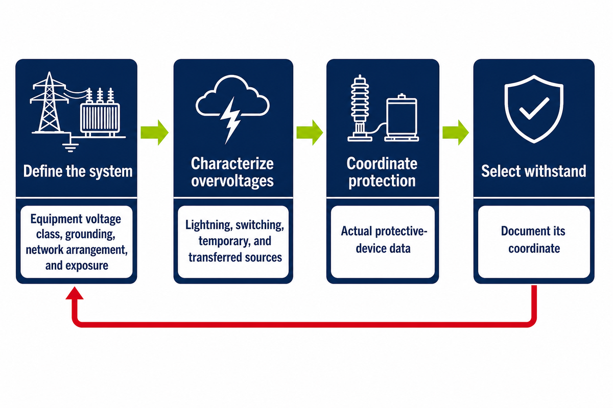
BIL coordination starts with representative overvoltages and the system conditions that shape them, then derives coordination and required withstand levels before one of the applicable standard BIL values is selected. Nominal voltage is one input, not a complete answer, and the responsible engineer must own the project calculation.
- Define the system — record equipment voltage class, grounding, network arrangement, and exposure.
- Characterize overvoltages — identify lightning, switching, temporary, and transferred sources that apply.
- Coordinate protection — use the applicable method and actual protective-device data.
- Select withstand — choose the standardized equipment rating and document its coordinate.
The public scope of IEC 60071-1 connects rated withstand voltages with highest voltage for equipment and phase-to-earth, phase-to-phase, or longitudinal insulation. Copied values can therefore fail even when the nominal system voltage looks familiar.
Boundary condition
Changes in grounding, line exposure, cable transition, protection location, equipment class, or environment reopen the coordination question. “We used it last time” is not a quantified engineering basis.
Changes in grounding, line exposure, cable transition, protection location, equipment class, or environment reopen the coordination question. “We used it last time” is not a quantified engineering basis.
IEC 60071-1 organizes one selection chain from project overvoltages to rated withstand; it never turns nominal voltage alone into a universal BIL choice.
The Arrester-to-Terminal Protection Window
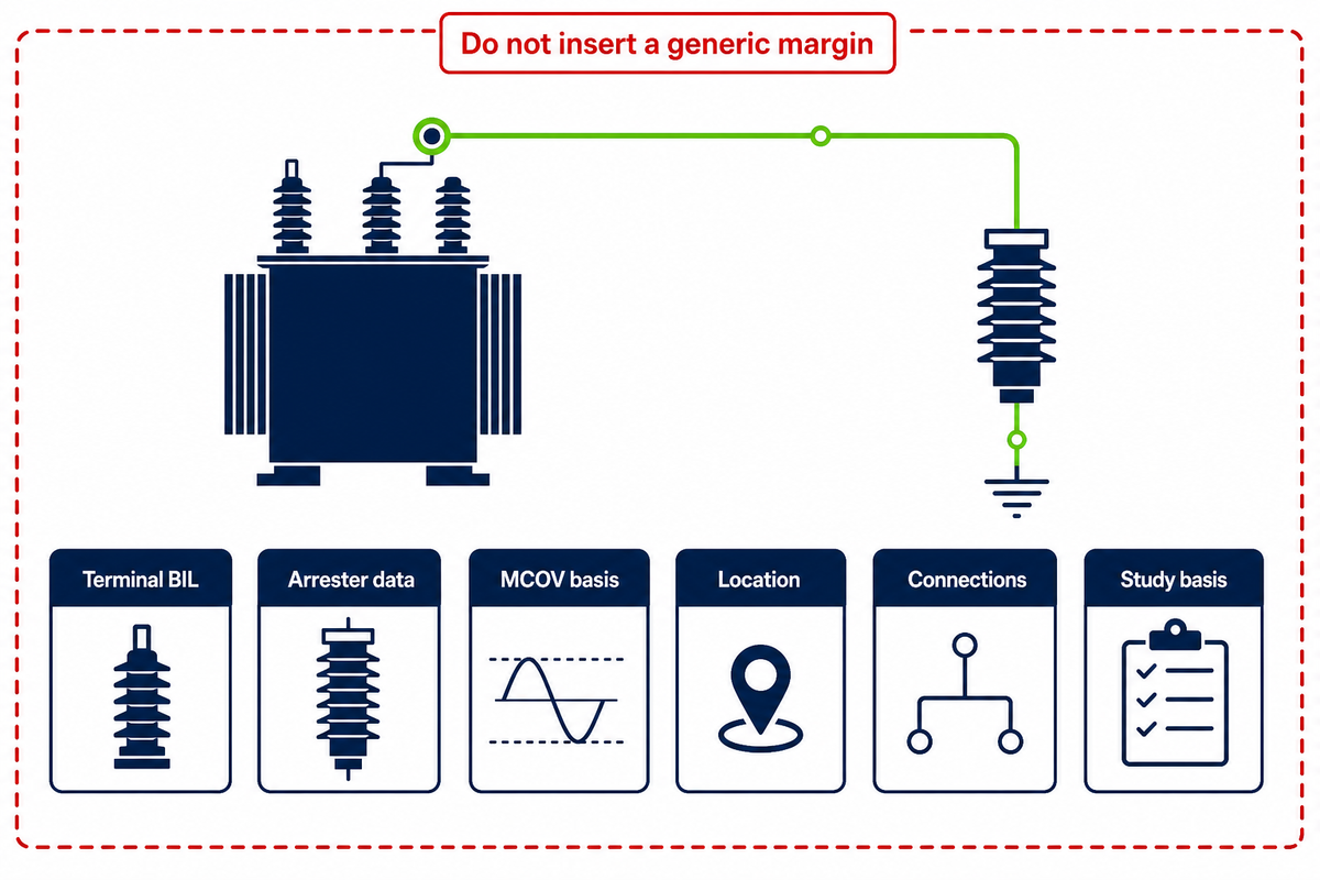
The Arrester-to-Terminal Protection Window compares transformer terminal withstand with the protective voltage that can actually appear at that terminal during lightning surges. Sound surge protection therefore needs the named terminal rating, arrester data, location, connections, grounding, and the applicable coordination method.
1. Terminal BIL
Named coordinate and standard
Named coordinate and standard
2. Arrester data
Relevant protective levels
Relevant protective levels
3. MCOV basis
System and grounding conditions
System and grounding conditions
4. Location
Mounting point and separation
Mounting point and separation
5. Connections
Lead and grounding arrangement
Lead and grounding arrangement
6. Study basis
Overvoltage and model assumptions
Overvoltage and model assumptions
IEEE C62.11-2020 covers metal-oxide surge arresters for alternating-current circuits above 1 kV (1,000 V), while IEEE C62.82.2-2022 provides insulation-withstand selection procedures. Named arrester classes alone cannot calculate the voltage at the transformer terminal.
“The higher the BIL, the higher the amplitude of the direct and indirect lightning voltage surges.”
The quotation comes from a specific Eskom study, not a universal rule. Its 22 kV (22,000 V) feeder included 372 pole-mounted transformers over 6 years, illustrating why line insulation, arresters, installation details, and equipment protection must be studied as one system.
Field-case boundary
The measured feeder was 156 km (156,000 m) long and used 400 kHz recording. Two scoped indirect-strike examples compared −120,000 A and −99,000 A inputs with induced estimates of 2,980,000 V and 3,560,000 V; nearby arresters limited recorded values to 133,000 V and 157,000 V.
The measured feeder was 156 km (156,000 m) long and used 400 kHz recording. Two scoped indirect-strike examples compared −120,000 A and −99,000 A inputs with induced estimates of 2,980,000 V and 3,560,000 V; nearby arresters limited recorded values to 133,000 V and 157,000 V.
Do not insert a generic margin. The often-repeated “15–20% protective margin” lacks the conditions needed for this project, so this guide does not use it.
The same 22,000 V case included 1,116 arresters. In a scoped recalculation that assumed no nearby trees and treated the three largest lightning currents as direct strikes, the study reported an induced overvoltage below 111,000 V; none of its measurements is a universal transformer setting.
Which Installation Inputs Can Change the Required Insulation Level?
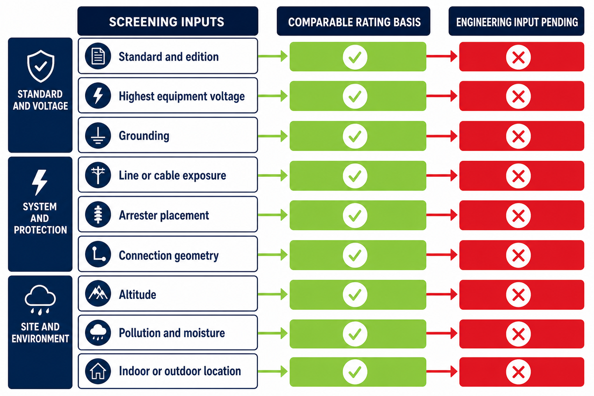
BIL selection remains unresolved until the inquiry identifies the governing standard, highest voltage for equipment, grounding, surge exposure, network arrangement, arrester position, altitude, pollution or clearance conditions, equipment location, and other environmental conditions. Do not specify higher BIL merely to cover missing system data or an unsuitable protection arrangement.
| Input | Why it changes the decision | If unknown | Limitations / Not suitable for |
|---|---|---|---|
| Standard and edition | Defines equipment and test scope | No comparable rating basis | Not a cross-standard equivalence |
| Highest equipment voltage | Anchors the coordination class | Voltage class unresolved | Not nominal voltage alone |
| Grounding | Shapes temporary overvoltage duty | Arrester basis incomplete | Not a generic earthing label |
| Line or cable exposure | Changes incoming surge behavior | Representative surge unclear | Not a mounting-style proxy |
| Arrester placement | Affects terminal protective voltage | Protection window unknown | Not device class alone |
| Connection geometry | Lead effects enter the terminal duty | Installation effect omitted | Not a nameplate parameter |
| Altitude | Rules stated for sea level may need correction for external insulation and air clearances | Atmospheric basis missing | Not a universal metre threshold |
| Pollution and moisture | Influence external insulation and creepage choices | Site duty incomplete | Not BIL alone |
| Indoor or outdoor location | Changes environmental exposure | Insulation system scope unclear | Not enclosure wording alone |
Keep external-insulation questions explicit: ask the engineer whether flashover risk, creepage distance, insulator geometry, or a conductive pollution layer belongs in the site assessment. In the wider distribution system study, separately record any required impedance or capacitance model, and identify whether the equipment is oil-immersed or of the dry type, because none of these entries substitutes for the named BIL coordinate.
How does altitude affect insulation performance?
Air density and atmospheric conditions can affect external insulation behavior and required clearances, so the buyer should state site altitude rather than copy a sea-level assumption. The applicable standard and equipment scope determine whether a correction factor or altered clearance is required; this guide deliberately avoids an unsourced “above X metres” shortcut.
Procurement response
If the project altitude is unknown, mark the BIL and external-insulation decision “engineering input pending.” Do not let a supplier silently assume sea level.
If the project altitude is unknown, mark the BIL and external-insulation decision “engineering input pending.” Do not let a supplier silently assume sea level.
IEC 60060-1 applies its general dielectric-test terminology above 1.0 kV AC (1,000 V) and 1.5 kV DC (1,500 V); the equipment standard still controls how dielectric strength is applied to a transformer.
How to Read BIL in a Transformer Schedule or Nameplate
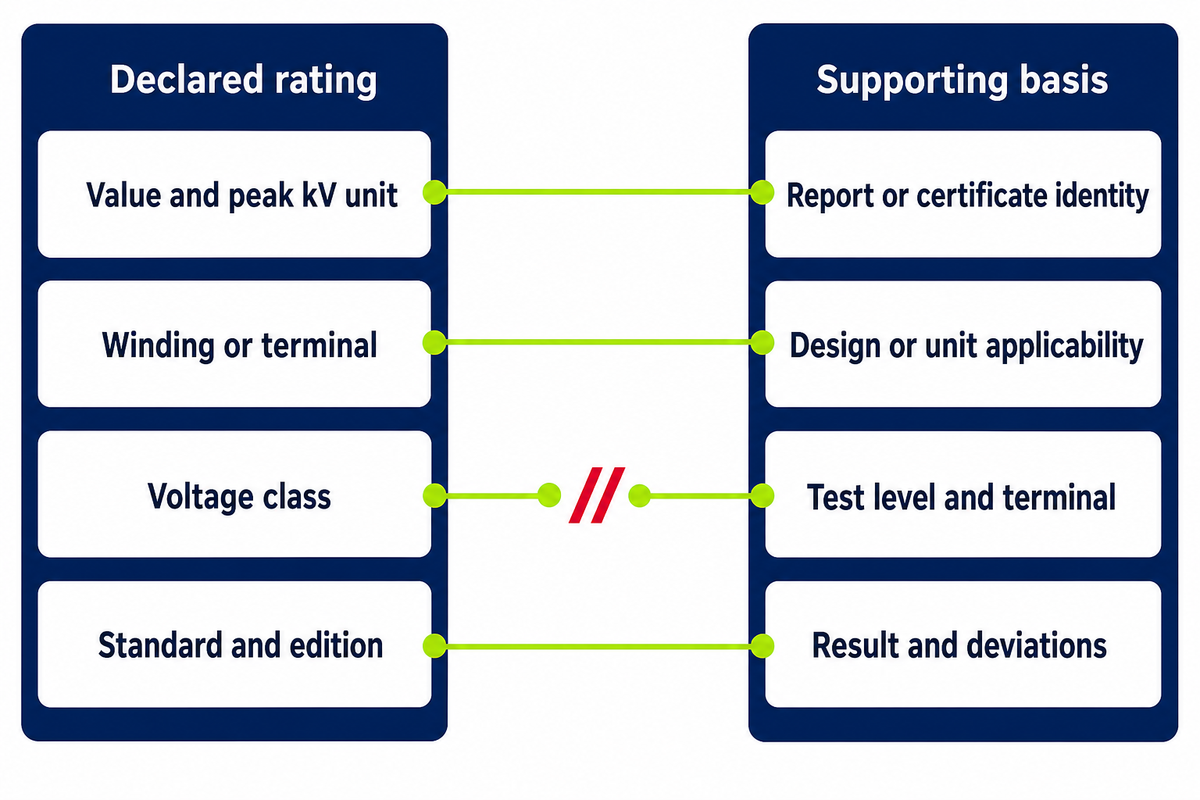
Schedule reviewers should check a BIL entry for six items: value, peak-kilovolt unit, winding or terminal, equipment voltage class, applicable standard and edition, and separate insulation levels or conditions. Missing coordinates turn a declared rating into an ambiguous bid comparison.
Nameplate-and-Test Proof Pair
The Nameplate-and-Test Proof Pair links the declared insulation rating to evidence that covers the same design, terminal, level, and standard.
Declared rating
- Value and peak kV unit
- Winding or terminal
- Voltage class
- Standard and edition
Supporting basis
- Report or certificate identity
- Design or unit applicability
- Test level and terminal
- Result and deviations
Plate photographs can settle transcription questions but do not prove that every test was performed on every supplied unit. The purchase specification and applicable standard decide which tests are routine, type, special, design-based, witnessed, or unit-specific. Searches for a transformer BIL rating table or standard BIL ratings for transformers can locate published values, but they cannot resolve a live project’s coordinate or standard.
Common mistake
Copying one rated BIL across high-voltage, low-voltage, neutral, and accessory interfaces without checking which insulation coordinate the source document covers.
Copying one rated BIL across high-voltage, low-voltage, neutral, and accessory interfaces without checking which insulation coordinate the source document covers.
One proof pair must preserve all 4 matching coordinates: design identity, terminal, test level, and governing standard.
What Test Evidence Should a Buyer Request?
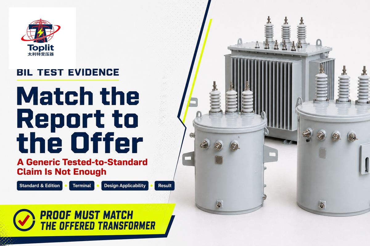
Reviewable BIL evidence identifies the purchase requirement, governing standard and edition, test category, applied level, impulse waveform, winding or terminal, design or unit applicability, result, and authorized report. It must show what insulation can withstand under the specified test and whether insulation failure occurred; “tested to standard” alone is not enough when the report cannot be matched to the offered transformer.
| Evidence type | Required match | Reject or clarify when |
|---|---|---|
| Purchase specification | Required level and coordinate | BIL line is unlabeled |
| Standard reference | Document and edition | Only “IEC” or “IEEE” appears |
| Test category | Applicable classification | Category is absent |
| Test level | Peak kV and polarity basis | Number differs from offer |
| Terminal identity | Named winding or coordinate | Whole unit is implied |
| Design identity | Offered design applicability | Report covers another design |
| Waveform record | Required test trace or parameters | Record is required but absent |
| Result | Pass, observations, and acceptance basis | Only a marketing statement exists |
| Authorization | Report number, date, and issuer | File cannot be traced |
IEEE C57.12.90-2021 publicly identifies dielectric tests within its liquid-immersed transformer test-code scope. IEC 60076-3 supplies the transformer insulation and dielectric-test context, while IEC 60060-1 remains the horizontal reference for general high-voltage test terminology.
Evidence hierarchy
The transformer-specific standard and purchase specification control applicability. Horizontal test-technique standards can define terms but do not prove that a particular offered design meets the purchaser’s requirement.
The transformer-specific standard and purchase specification control applicability. Horizontal test-technique standards can define terms but do not prove that a particular offered design meets the purchaser’s requirement.
The current IEC 60060-1 publication covers 4 voltage-test families; transformer proof still needs its specific product standard and matching report.
From a BIL Requirement to a Pole-Mounted Transformer Inquiry
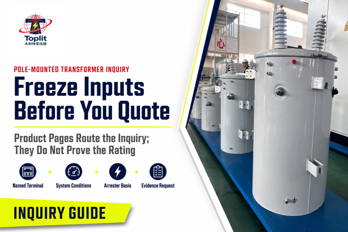
Verified BIL requirements should enter the supplier inquiry as frozen engineering inputs, accompanied by the named terminal, standard, system conditions, arrester basis, site conditions, and evidence request. Product-family pages help route the inquiry; they do not prove a configuration-specific rating or test result.
1. Engineering requirement
Freeze the coordinated BIL inputs and unresolved assumptions.
Freeze the coordinated BIL inputs and unresolved assumptions.
2. Supplier evidence response
Return the offered rating, deviations, and matching documentation.
Return the offered rating, deviations, and matching documentation.
Talite’s overhead single-phase inquiry inputs page provides product-family and inquiry context, including a request for the utility-required BIL or insulation basis. Use it after the responsible engineer has resolved the selection inputs.
Keep the scope cleanUse the fault-zone protection workflow for the wider protection architecture and the network design-basis workflow for network planning.
The product page requests 8 broader inquiry inputs; the BIL Coordination Brief below covers only the BIL subset and doesn’t replace kVA sizing or installation design.
The BIL Coordination Brief
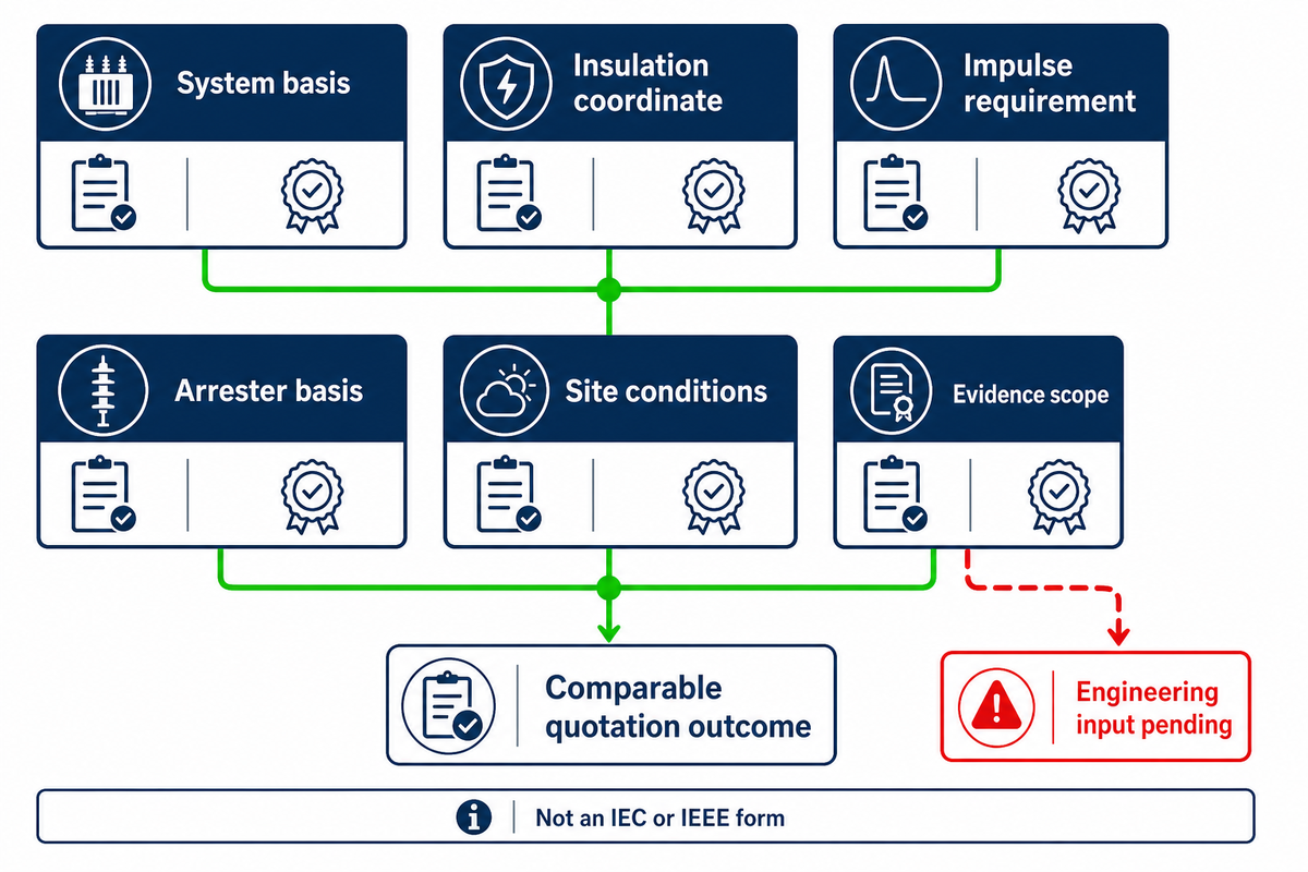
In this guide, the BIL Coordination Brief is an editorial procurement checklist that groups six coordinated inputs for comparing quoted impulse ratings across suppliers. It is not an IEC or IEEE form.
RFQ checklist — copy these into your quote request:
| Parameter | Required entry | Why it matters | How to verify |
|---|---|---|---|
| System basis | Highest equipment voltage, grounding, controlled-overvoltage assumptions | Sets coordination context | Approved single-line and study basis |
| Insulation coordinate | Winding, terminal, or path | Prevents whole-unit ambiguity | Schedule and drawing |
| Impulse requirement | Peak kV plus standard and edition | Creates a comparable rating | Purchase specification |
| Arrester basis | Protective data, location, and connections | Defines terminal protection window | Arrester data and layout |
| Site conditions | Altitude, pollution, exposure, and location | Controls external insulation assumptions | Site data sheet |
| Evidence scope | Test category, report, design match, and result | Turns a claim into reviewable proof | Authorized report set |
When one field remains unknown, return it to the project engineer rather than inserting a standard BIL from a generic chart. Higher-BIL alternatives can be quoted as documented deviations, but they shouldn’t replace the coordinated base requirement or conceal mismatched arrester or test evidence.
| Bid condition | Action |
|---|---|
| All 6 inputs match | Proceed to technical evaluation |
| Site condition unresolved | Hold insulation approval |
| Higher-BIL alternative | Record cost, fit, and coordination deviation |
| Evidence does not match | Reject proof or request a corrected report |
Separate this insulation packet from load selection. Use the load-to-nameplate capacity method for capacity, and the overhead-versus-underground route comparison for installation-format tradeoffs.
Key takeaway
This guide’s comparison method uses 6 coordinated inputs; a larger kV number cannot repair a missing coordinate, site assumption, arrester basis, or evidence match.
Frequently Asked Questions
What does BIL rating stand for and what does it represent?
BIL stands for Basic Impulse Insulation Level, the peak impulse withstand rating assigned to a specified insulation path under the named equipment standard and test basis.
Read the number with its standard, winding or terminal, equipment voltage class, and test basis. BIL contributes to insulation coordination, but it is not a promise that every surge condition is safe or that every terminal has the same rating. The purchase file must also identify the protected coordinate and evidence scope before approval.
Is transformer BIL the same as operating voltage?
Transformer BIL is not operating voltage: BIL describes standardized impulse withstand duty, while operating voltage describes the transformer’s continuous electrical duty in normal service conditions.
Operating voltage identifies continuous system duty, while BIL identifies a standardized impulse withstand condition. Procurement schedules can also include a short-duration power-frequency withstand entry, which is a third requirement. Reject unlabeled kV columns because a shared unit does not make these duties interchangeable. Each field needs its own test or rating label.
Does a higher BIL always mean a better transformer?
Higher BIL does not universally mean a better transformer; suitability depends on the coordinated project requirement, correct insulation coordinate, actual installation conditions, and matching evidence.
Project coordination may justify a higher standardized level under the governing standard. It cannot correct unsuitable arrester data, poor placement, missing grounding information, unresolved clearances, or a report that covers another design. Compare the coordinated requirement and proof package rather than awarding the bid to the largest number during evaluation.
Is BIL shown on a transformer nameplate?
BIL may appear on a transformer nameplate, schedule, drawing, or data sheet, but the buyer must still verify its terminal, standard, unit, and evidence scope.
Wherever it appears, confirm the peak-kV unit, winding or terminal, equipment voltage class, governing standard, and whether separate insulation levels apply.
How should a surge arrester be coordinated with transformer BIL?
Coordinate a surge arrester by comparing transformer terminal withstand with the protective voltage that can reach that terminal under the governing method and installation conditions.
Request the transformer’s terminal BIL and the arrester’s relevant protective data, then include maximum continuous operating conditions, system grounding, overvoltage source, arrester location, connections, and separation or lead effects. Apply the method and edition that govern the installation; a universal percentage margin is not reliable without those conditions.
What is the difference between BIL and SIL?
BIL concerns lightning-impulse withstand, while SIL concerns switching-impulse insulation duty; the applicable equipment and insulation coordination standards determine whether either or both ratings are required.
The terms are not interchangeable, and both are not automatically required for every distribution transformer. IEC 60076-3 publicly distinguishes switching-impulse treatment above 72.5 kV (72,500 V); the applicable equipment and insulation-coordination standards decide what the project needs.
Need a configuration-specific transformer review?
Send the BIL Coordination Brief with your system and site requirements so Talite can confirm the review scope and identify which configuration-specific documents can be included in the quotation.
References & Sources
- IEC 60071-1:2019, Insulation co-ordination International Electrotechnical Commission
- IEC 60076-3:2013+A1:2018, Power transformers, insulation levels and dielectric tests International Electrotechnical Commission
- IEC 60060-1:2025, High-voltage test techniques International Electrotechnical Commission
- IEEE C62.11-2020, Metal-Oxide Surge Arresters IEEE Standards Association
- IEEE C62.82.2-2022, Insulation withstand selection guide IEEE Standards Association
- Lightning Tamed T&D World, Willem van Schalkwyk and John van Coller
- IEEE C57.12.90-2021, Liquid-Immersed Transformer Test Code IEEE Standards Association
Editorial transparency: This guide was prepared from public standard scopes, named trade-press evidence, and Talite product-family context. It doesn’t claim project-specific engineering approval or a test result for an unreviewed configuration.
![Pad-Mounted Transformer: How It Works [2026 Guide]](https://toplit-transformer.com/wp-content/uploads/2026/08/pad-mounted-transformer-guide-featured-150x150.png)
![Single Phase Pad Mounted Transformer Guide [2026]](https://toplit-transformer.com/wp-content/uploads/2026/08/single-phase-pad-mounted-transformer-guide-featured-1-150x150.png)