Get in touch with Toplit Transformer Co., Ltd Company

![Pad-Mounted Transformer: How It Works [2026 Guide]](https://toplit-transformer.com/wp-content/uploads/2026/08/pad-mounted-transformer-guide-featured.png)
Talite Transformer Technical Guide
An evidence-led guide to the energy path, component roles, public safety boundaries, project handoffs, and lifecycle records behind ground-level distribution equipment.
Updated August 2026
A Pad-Mounted Transformer is easy to recognize and easy to misunderstand. That locked steel cabinet sits at ground level, often near homes, shops, factories, or campuses. What happens inside is only one part of the story. Underground cables, utility operating rules, civil work, protection, records, and public-access controls all shape how the unit can be used safely.
This guide explains that complete system without becoming a product catalogue. It follows electrical power from the incoming medium-voltage circuit to the lower-voltage service, then shows who owns each decision from the pad drawing through maintenance and replacement. Ratings, available configurations, quotations, and supplier-specific options belong on Talite’s commercial page, not here.
Quick answer
A pad-mounted transformer lowers distribution voltage inside a secured ground-level enclosure. Underground cables carry power in and out. Approved drawings, utility rules, and qualified procedures govern its configuration and use.
The guide’s core boundary
Members of the public can observe and report. Qualified personnel diagnose and work. Utilities, engineers, manufacturers, installers, owners, and local authorities approve different parts of the system; one product label never replaces those approvals.
Guide Quick Specs
- trace the energy path through nine functional component groups;
- separate phase, feed, and primary-interface terminology;
- match a standard to the evidence it can actually support;
- route ten common project decisions to the right approval seat;
- classify outside observations without attempting energized diagnosis;
- connect commissioning records to inspection, repair, and end-of-life planning.
What Is a Pad-Mounted Transformer, and What Is It Not?
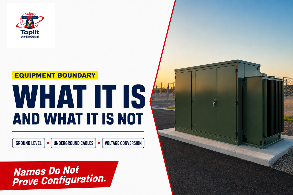
A pad-mounted transformer is a ground-level distribution transformer in a locked enclosure, normally connected to underground primary and secondary cables. It changes voltage for a defined part of an electrical distribution system. By itself, the term doesn’t identify the phase, circuit arrangement, exact rating, fluid, accessory package, ownership, or site rules.
Active IEEE product-scope pages distinguish single-phase and three-phase pad-mounted equipment. That’s useful for classification, but the scope of a standard isn’t a manufacturer’s model list and doesn’t prove that a specific unit meets a project’s contract. Unit-level evidence comes from the approved nameplate, drawings, purchase documents, and acceptance records.
| Term | Primary role | Do not infer from the name |
|---|---|---|
| Pad-mounted transformer | Ground-level voltage conversion connected to an underground distribution system | Phase, feed, interface, rating, protection, or ownership |
| Pole-mounted transformer | Voltage conversion on an overhead distribution structure | That it is a direct substitute at an underground site |
| Compact substation | Packaged assembly that may combine switching, transformation, and low-voltage distribution | The same access, testing, or product-standard scope |
| Switchgear cabinet | Switching, isolation, or protection without the transformer’s voltage-conversion function | That every green utility cabinet contains a transformer |
Scope references: IEEE C57.12.34-2022 and IEEE C57.12.38-2025.
The 10-Type Search-Language Boundary Map
Search language often mixes system roles, installation descriptions, equipment types, standards names, and unverified benefit claims. Below, the map keeps those word families available for document review without treating them as interchangeable specifications.
| Language type | Terms a reader may encounter | How this guide treats them |
|---|---|---|
| 1. System role | power distribution, electric power distribution, power distribution systems, and energy distribution | System context, not a unit specification |
| 2. Network context | distribution networks, distribution lines, power transmission and distribution, and modern power infrastructure | The surrounding grid, not the cabinet alone |
| 3. Installation wording | mounted on a concrete pad, designed for outdoor installation, underground power, and underground power distribution systems | A location description that still requires civil and utility approval |
| 4. Equipment wording | electrical transformer, type of electrical transformer, three-phase pad-mounted transformers, and the search variant “3 phase pad mounted transformers” | Classification language, not proof of project fit |
| 5. Electrical input | primary voltage, primary power, voltage level, high-voltage, kV, kVA, and power supply | Fields that need exact values and owners |
| 6. Design and work | transformer design, fuses and switches, installation and maintenance, and power transformers | Separate engineering, accessory, and qualified-work scopes |
| 7. Standards shorthand | IEEE, NEMA, CSA, and UL | Organization names; cite the applicable document and edition |
| 8. Use environment | used in residential areas, used in underground systems, industrial environments, urban infrastructure, and harsh environmental conditions | Application context that requires site evidence |
| 9. Grid-change language | renewable energy, wind power, and sustainable energy | Possible load or network drivers, not product features |
| 10. Benefit and selection claims | reliable power, efficient power, uninterrupted power, long service life, safety and durability, space-saving, efficient power delivery, reliable and efficient, and choosing or selecting the right transformer | Claims to verify, not benefits implied by the category name |
In short, the role of pad-mounted transformers is voltage conversion within a governed network interface. A tamper-resistant enclosure is an access-control characteristic, not proof that the surrounding site is risk-free. Likewise, “efficient and reliable power” may describe a project objective, but reviewers need a design basis, loss evidence, protection, installation, load, and operating history before they can measure it. Choosing the right transformer therefore starts with owned system inputs, not search-language benefits.
How Does a Pad-Mounted Transformer Work?
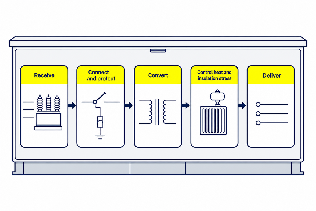
Incoming medium-voltage power reaches the primary compartment through underground cable, passes through the approved connection and protection arrangement, and energizes the transformer’s primary winding. Magnetic flux in the core links the secondary winding, which supplies a lower-voltage output. Insulation, fluid or another cooling system, grounding, and the enclosure support that conversion.
- Receive: the serving circuit reaches the primary cable interface defined by the utility one-line diagram.
- Connect and protect: terminals, connectors, switching provisions, fuses, arresters, or other devices perform only the functions assigned in the approved design.
- Convert: alternating current in the primary winding produces changing magnetic flux in the core and induces voltage in the secondary winding.
- Control heat and insulation stress: the tank, dielectric system, cooling surfaces, and internal clearances support the transformer’s declared duty.
- Deliver: secondary terminals connect to service conductors and downstream distribution equipment.
No step in that explanation authorizes operation. A diagram can show the intended energy path while omitting the actual switch position, cable status, test result, or work boundary. Those facts come from current system records and qualified field procedures.
What does a pad mount transformer do?
A pad mount transformer creates a usable voltage interface between an underground distribution circuit and the loads served nearby. It doesn’t generate electricity, and its cabinet isn’t a complete substation by definition. Voltage conversion happens in the unit, while the surrounding system supplies cable routing, fault protection, grounding, switching rules, metering, and downstream distribution.
Whether it serves one building, several homes, a campus area, or an industrial load depends on the approved network design. Its presence at ground level also creates an access-control obligation: authorized crews must keep the enclosure secured and the work area available, while planners account for connected underground cables before excavation. Product-specific questions start only after the service voltage, load basis, utility circuit, and site constraints are known.
The 9-Component Energy Chain: What Each Part Does
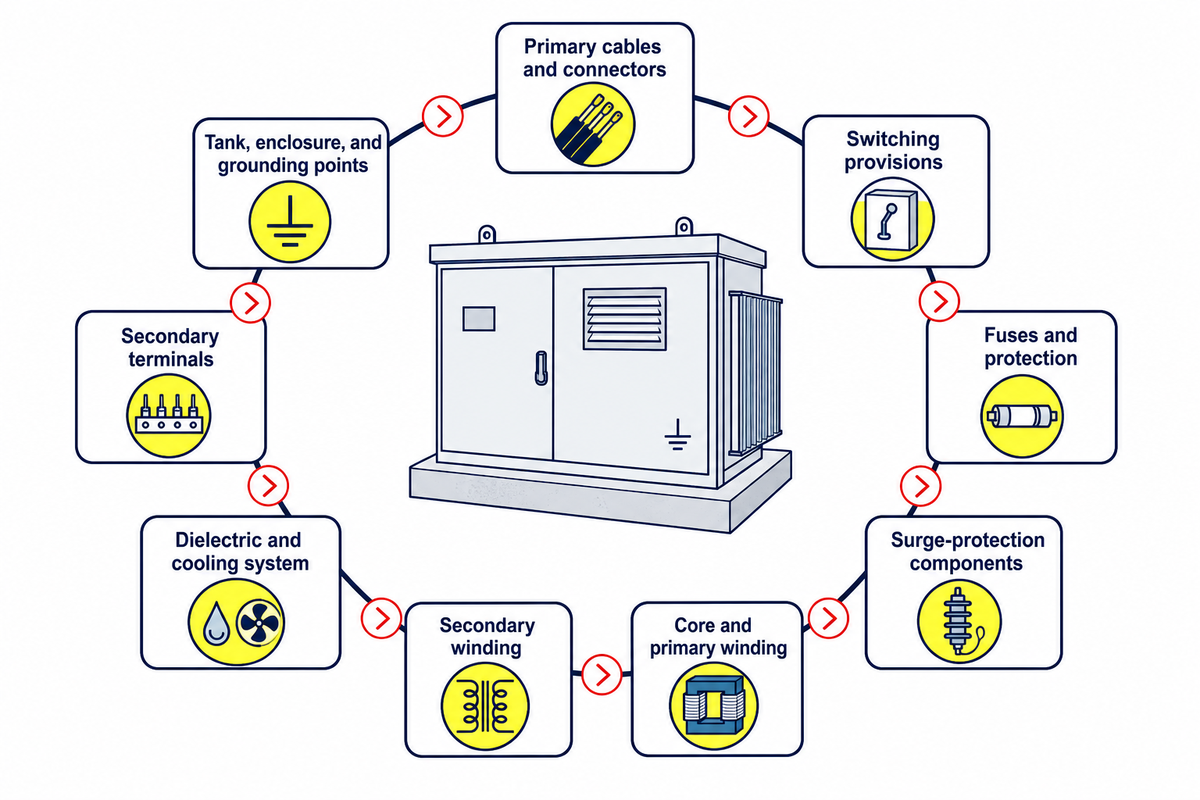
Our 9-Component Energy Chain connects each major component group to a function, an evidence source, and a limit. It helps a reader understand a drawing without assuming that every design contains the same accessories. Used here, this table is educational; it isn’t an inspection, switching, or maintenance procedure.
| Component group | Function in the chain | Normal evidence interface | Important limit |
|---|---|---|---|
| 1. Primary cables and connectors | Bring the medium-voltage circuit to the unit | Utility one-line, cable schedule, terminal drawing | Connector appearance does not prove de-energization |
| 2. Switching provisions | Support the approved isolation or circuit arrangement when specified | Operating diagram, device data, utility procedure | Presence does not grant switching authority |
| 3. Fuses and protection | Respond to assigned abnormal-current conditions within a coordinated scheme | Protection study, approved schedule, test records | A fuse does not explain why an event occurred |
| 4. Surge-protection components | Limit specified transient overvoltage exposure when included | Insulation-coordination basis and accessory drawing | They are not universal or self-verifying |
| 5. Core and primary winding | Create the magnetic field from the incoming alternating current | Approved design data and factory test evidence | An external observer cannot assess internal condition |
| 6. Secondary winding | Produces the lower-voltage output relationship | Nameplate, ratio data, factory and field records | Voltage alone does not prove load suitability |
| 7. Dielectric and cooling system | Provides insulation and transfers operating heat | Supplier data, nameplate, fluid and condition records | The cabinet style does not prove fluid type |
| 8. Secondary terminals | Transfer output to the service conductors | Terminal drawing, conductor design, installation records | Terminal count does not approve conductor loading |
| 9. Tank, enclosure, and grounding points | Contain, protect, restrict access, and provide defined bonding interfaces | Enclosure standard, coating record, grounding design, site inspection | A locked door does not remove external impact or excavation risk |
Component functions are synthesized from standard scopes and ordinary transformer principles. Test-method scope is checked against IEEE C57.12.90-2021; the approved design determines which tests and accessories apply.
Single-Phase, Three-Phase, Dead-Front, and Live-Front: Four Labels That Answer Different Questions
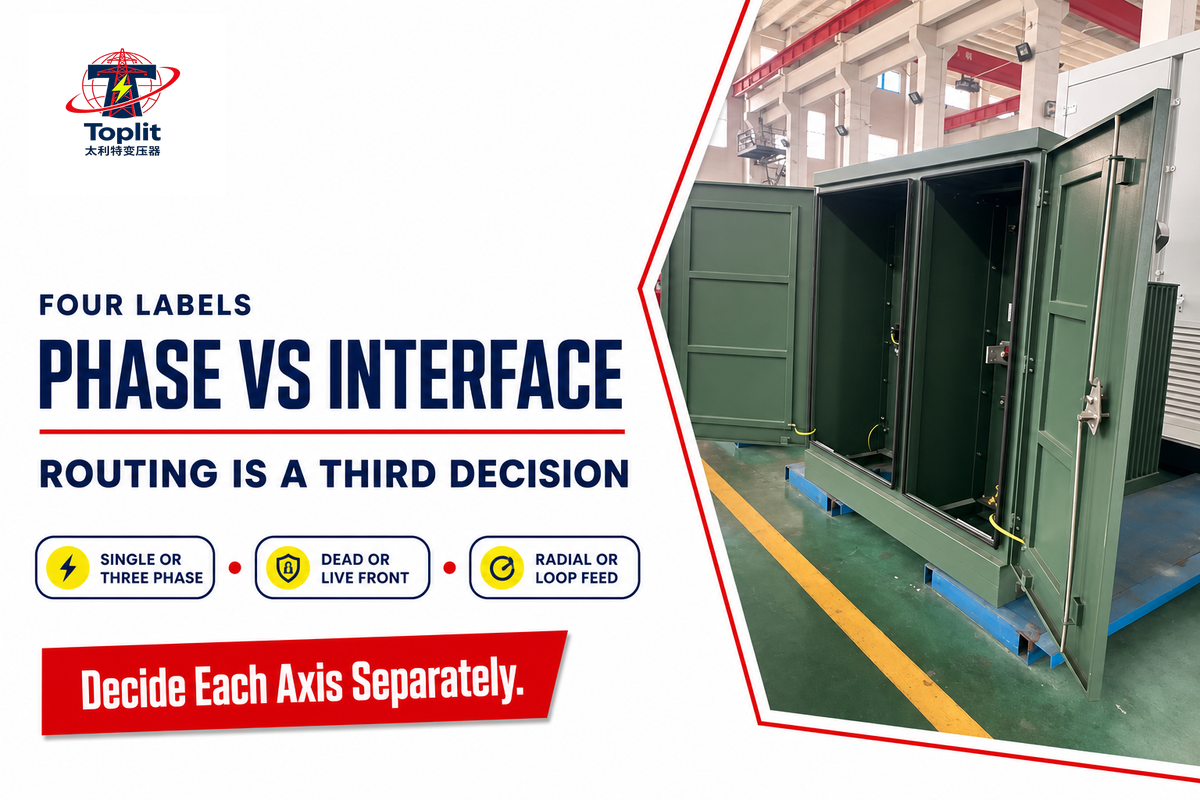
Single-phase and three-phase describe the electrical phase arrangement; dead-front and live-front describe the primary interface presented inside the authorized-access compartment. Those component functions establish the energy path; radial feed and loop feed form another axis: circuit routing. Treating these labels as one product list hides the decisions that the utility and engineer still need to make.
| Label | What it describes | What it does not decide | Who confirms it |
|---|---|---|---|
| Single-phase | Phase arrangement for the served system | Feed routing, interface, rating, or site acceptance | Engineer and serving utility |
| Three-phase | Three-phase electrical supply arrangement | Whether the primary is radial or loop feed | Engineer and serving utility |
| Dead-front | An insulated, shielded primary-interface arrangement | That equipment is de-energized or safe to touch | Utility, engineer, and approved drawings |
| Live-front | An interface where energized parts may be exposed after authorized access | Feed routing, phase, or work permission | Utility, engineer, and qualified-work procedure |
Readers who need more detail can use the dedicated single-phase pad-mounted transformer guide. Product questions belong on the pages for single-phase pad-mounted units or three-phase pad-mounted distribution transformers. Those links are handoffs, not claims that one configuration fits every network.
Which Standards Govern the Unit, Enclosure, and Tests?
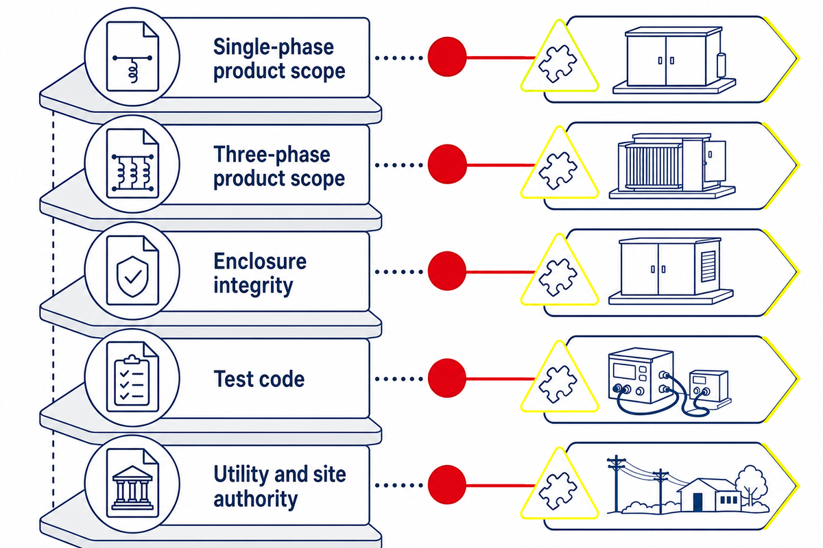
No single citation proves the entire equipment-and-site package. Those four equipment labels are only one evidence layer; product-family characteristics, enclosure integrity, test methods, federal energy rules, utility interfaces, and local installation acceptance come from different documents. Contracts must also identify the required edition instead of assuming that the newest public page automatically governs an existing order.
| Document or authority | Evidence question | What it cannot prove alone |
|---|---|---|
| IEEE C57.12.38-2025 | Public scope for a defined family of single-phase pad-mounted units | Manufacturer availability or project acceptance |
| IEEE C57.12.34-2022 | Public scope for a defined family of three-phase pad-mounted units | Every site, accessory, or utility requirement |
| IEEE C57.12.28-2023 | Enclosure integrity and coating requirements within its scope | Electrical performance or complete installation safety |
| IEEE C57.12.90-2021 | Test code for liquid-immersed distribution, power, and regulating transformers | Which tests the purchase contract requires |
| 10 CFR Part 431, Subpart K | Covered U.S. distribution-transformer definitions and energy-conservation requirements | Global applicability, site design, or utility approval |
| Serving utility and site authority | Circuit interface, civil details, access, local clearances, inspections, and release | Factory conformance outside their stated review |
How to read the numbers without turning them into a product range
The active three-phase scope describes 60 Hz, liquid-immersed, self-cooled units rated 10 MVA and smaller, with a 34.5 kV nominal high-voltage limit and a 15 kV nominal low-voltage limit. For unit orientation, 10 MVA equals 10,000 kVA, 34.5 kV equals 34,500 V, and 15 kV equals 15,000 V. These conversions clarify the document title; they don’t state a Talite offering.
The active single-phase scope describes 60 Hz units rated 250 kVA and smaller. Its public boundary lists 34,500 GrdY/19,920 V and below on the high-voltage side and 480/240 V and below on the low-voltage side. In equivalent notation, 250 kVA is 0.25 MVA, 34,500 V is 34.5 kV, and 19,920 V is 19.92 kV. Don’t mix a 15 kV scope boundary with a 480 V or 240 V boundary, and don’t compare the 10 MVA and 250 kVA ceilings as if they were supplier range cards.
The 9-Evidence Numeric Scope Register
Numbers become useful only after their source and scope are visible. This register keeps product-standard boundaries, local siting examples, regulatory modeling, and research funding in separate evidence categories. Metric conversions are rounded for orientation; the original authority document remains controlling.
| Evidence type | Published number | Permitted use | Forbidden inference |
|---|---|---|---|
| 1. Three-phase frequency | 60 Hz | C57.12.34-2022 public scope | Global frequency availability |
| 2. Three-phase voltage boundaries | 34.5 kV high; 15 kV low | Active standard scope limits | A Talite model or site voltage |
| 3. Single-phase frequency | 60 Hz | C57.12.38-2025 public scope | Project frequency approval |
| 4. Single-phase primary boundaries | 34,500 V GrdY/19,920 V | Active standard scope limits | A selected primary voltage |
| 5. Single-phase secondary boundaries | 480 V/240 V | Active standard scope limits | The required service voltage |
| 6. LLNL local access example | 10 ft, about 3.05 m | That owner standard’s three-phase loop-feed scope | A universal public clearance |
| 7. SELCO local access example | 10 ft front (about 3.05 m); 4 ft sides (about 1.22 m) | That municipal utility’s work-space guidance | Another utility’s requirement |
| 8. Logan local siting examples | 10 ft front (about 3.05 m); 10 ft combustible (about 3.05 m); conditional 3 ft noncombustible (about 0.91 m) | That utility’s stated conditions | A national building rule |
| 9. Federal context examples | 32 years in broad rule modeling; $200,000 Phase I monitoring award | Policy-model and funded-development context | Pad-unit life guarantee or monitoring adoption rate |
A final notation check prevents two common reading errors: a stated 60 Hz frequency can’t be compared with a 34.5 kV voltage limit. 60 Hz is frequency, while 34.5 kV or 34,500 V is voltage. Likewise, 19.92 kV and 19,920 V are equivalent notation; 15 kV equals 15,000 V; and 480 V and 240 V remain distinct low-voltage boundaries in the cited single-phase scope. Both active product-scope descriptions use a 60 Hz frequency boundary. As a cross-check, the active scope texts independently repeat 60 Hz, 34.5 kV, 15 kV, 480 V, and 240 V. None is an orderable value until the project and manufacturer confirm it.
The April 2024 U.S. final rule became effective July 8, 2024 and states that covered equipment manufactured or imported on or after April 23, 2029 must meet the amended standards. A June 2026 Federal Register action is a request for information, not a replacement final rule. Check the current codified text and project jurisdiction before relying on either date. Talite’s covered-transformer scope checker can organize an initial screening, but it isn’t an authority determination or legal advice.
The 5-Seat Responsibility Relay
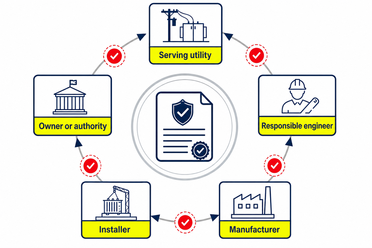
The 5-Seat Responsibility Relay routes each decision through the utility, engineer, manufacturer, installer, or owner/authority, with the required evidence visible before production or energization. It’s a coordination method, not a universal contract chart. Projects may combine seats or reassign work, but the approving party and controlling record should remain visible.
| Decision | Initiating seat | Approval seat | Evidence handed forward |
|---|---|---|---|
| 1. Service characteristics | Owner and engineer | Serving utility | Service letter, one-line diagram, voltage basis |
| 2. Load basis | Owner | Responsible engineer | Load schedule, demand basis, operating cases |
| 3. Phase and feed | Engineer | Serving utility | Approved network one-line and operating basis |
| 4. Protection interface | Engineer and utility | Named system authority | Coordination study and approved device schedule |
| 5. Equipment design | Manufacturer | Purchaser, engineer, and utility as contracted | Approved drawings, data sheets, exceptions list |
| 6. Pad and conduit design | Engineer or utility | Civil authority and utility | Stamped pad drawing, conduit plan, site details |
| 7. Installation | Installer | Engineer, owner, utility, or inspector by scope | Inspection, torque, grounding, cable, and as-built records |
| 8. Acceptance testing | Qualified test provider | Named project authority | Approved procedure, calibrated results, exceptions disposition |
| 9. Energization release | Project team | Serving utility or owner authority | Release checklist and closed deficiencies |
| 10. Operating custody | Owner or utility | Named asset authority | Asset record, access rules, maintenance and incident history |
A current Lawrence Livermore National Laboratory site standard illustrates why the relay matters. Within its limited scope, engineers approve pad design, qualified third parties perform acceptance testing, and the owner approves energization. Another site can allocate those tasks differently. Copying a responsibility without copying its governing contract creates a gap, not compliance.
“A product name starts the discussion; the one-line, interface drawing, and custody records decide what the system actually is.”
From Approved Pad Drawing to Energization: Handoffs, Not DIY Steps
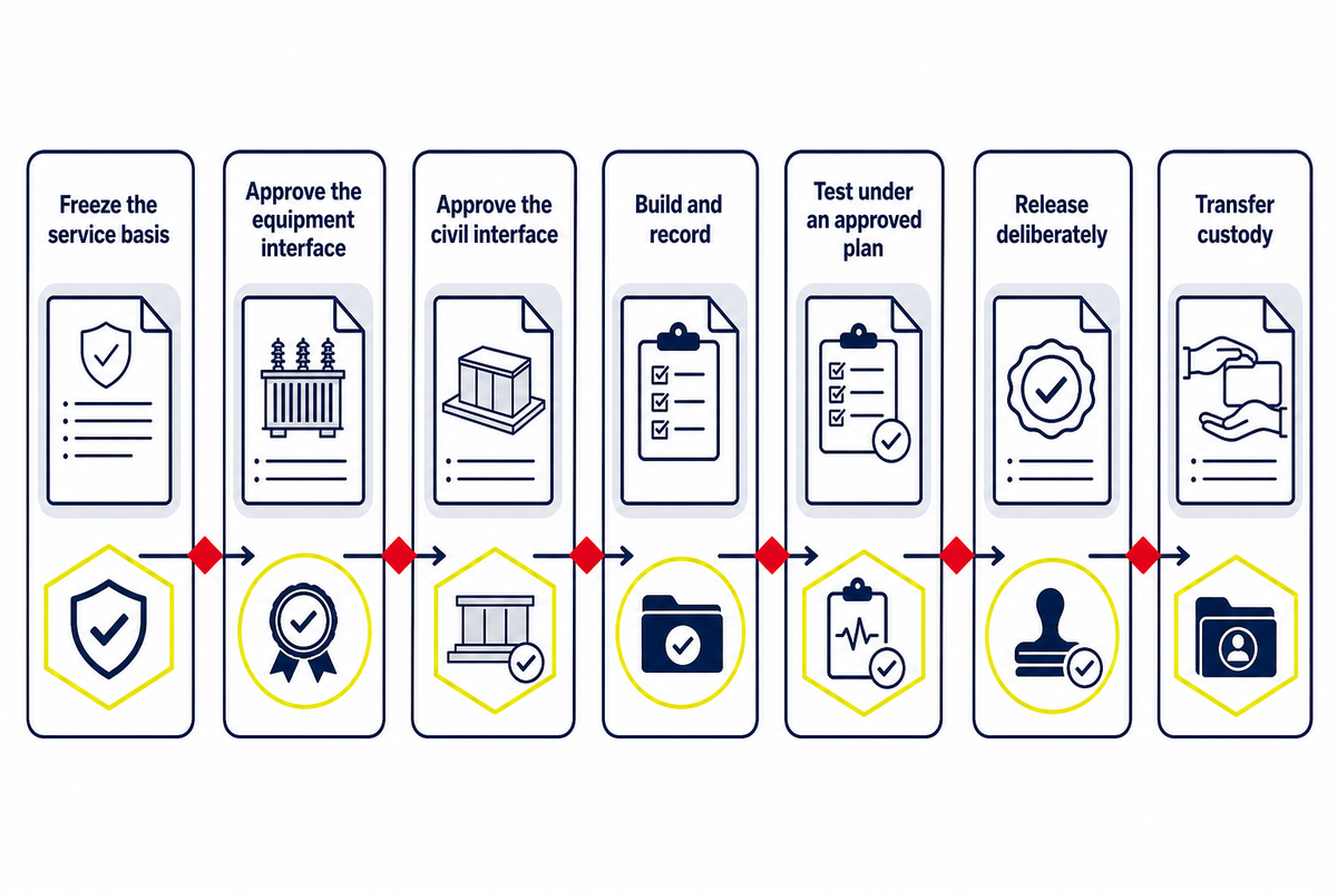
A safe project sequence is a chain of approved evidence, not a set of do-it-yourself installation instructions. Each step closes one uncertainty before the next party relies on it. Work on cables, compartments, grounding, protection, or energized equipment remains with qualified and authorized personnel under the controlling procedure.
- Freeze the service basis: utility circuit, phase, primary and secondary voltage, metering boundary, and operating ownership.
- Approve the equipment interface: drawings identify terminal arrangement, dimensions, cable entries, accessories, grounding points, and declared ratings.
- Approve the civil interface: the responsible designer closes pad, conduit, drainage, access, impact protection, and site-environment questions.
- Build and record: authorized installers produce the inspection and as-built evidence required by contract.
- Test under an approved plan: qualified personnel perform the applicable checks and disposition exceptions.
- Release deliberately: the named authority confirms that open items are closed before energization.
- Transfer custody: the owner receives nameplate data, drawings, test results, operating limits, contacts, and maintenance history.
The equipment discussion starts after the system basis exists. Talite’s page for pad-mounted transformer configurations is the right destination for drawings, supplier-specific options, and project review. This article deliberately doesn’t duplicate its selection path, rating information, or quotation inputs.
When Not to Use This Guide as a Buying Specification
Don’t use this article to release a purchase while the utility service basis, load schedule, phase, primary and secondary voltages, feed arrangement, protection responsibility, terminal interface, site drawing, or acceptance evidence remains unresolved. This guide also can’t settle which 60 Hz IEEE product scope the contract invokes, whether U.S. energy-conservation rules cover the equipment, or whether a local authority requires additional fire, drainage, access, or environmental measures. Those are approval questions, not missing blog paragraphs.
A useful stop rule is simple: if a choice changes system voltage, cable connection, protective coordination, civil location, energized-work boundary, or acceptance test, send it to the named approval seat before asking a supplier to manufacture. A supplier can explain available construction and evidence; it can’t silently assume the utility’s network, the engineer’s load basis, or the owner’s site risk. This boundary keeps the informational guide from competing with the commercial solution page and prevents general education from being mistaken for a project authorization.
Is It Safe to Live or Work Near a Pad-Mounted Transformer?
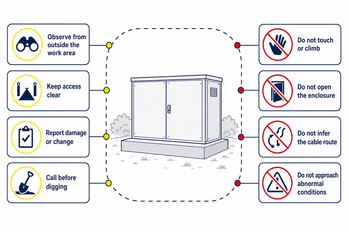
Ordinary proximity to intact, secured equipment is different from permission to touch, climb, dig, store materials, landscape, or work around it. Keep the cabinet and required crew-access area clear, follow the serving utility’s local rules, and report damage or abnormal conditions. Never use a generic online clearance as site approval.
Public-safe actions
- observe from outside the work area;
- keep children, vehicles, landscaping, and stored objects away;
- contact the utility or listed owner about damage, oil, odor, or a marked change in sound;
- use the applicable call-before-you-dig process before excavation.
Do not
- touch, sit on, climb, decorate, or obstruct the enclosure;
- open a door, defeat a lock, or insert anything through an opening;
- assume buried cables follow a visible straight line;
- approach after impact, smoke, fire, arcing, exposed conductors, or major leakage.
Is it safe to live next to a pad-mounted transformer?
Living or working near an intact pad-mounted transformer isn’t the same as entering its controlled work area. Safe placement for a specific site depends on utility rules, equipment access, building openings, fire and fluid considerations, barriers, local code, and the authority having jurisdiction.
Municipal examples show why one number can’t be universal: published access and combustible-clearance conditions vary by owner and construction context. Obtain the serving utility’s current written requirement before fixing the pad, conduits, landscaping, fence, or building layout. After installation, keep the required access area open and treat the connected underground cables as part of the hazard boundary. If a cabinet is open, displaced, struck, leaking, smoking, arcing, or exposing conductors, keep away and contact emergency services and the utility. Normal appearance doesn’t authorize touching or opening it.
The 10-Signal Safe-Observation Board: Normal, Report, or Emergency?
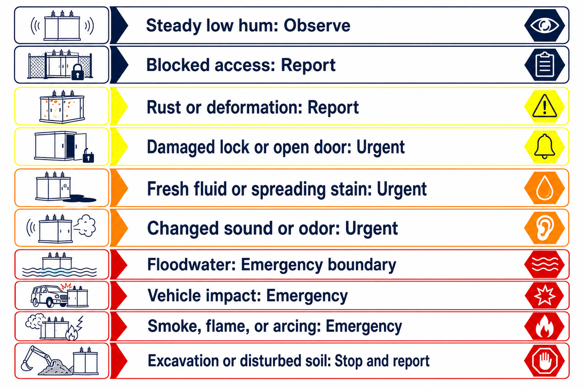
The 10-Signal Safe-Observation Board converts outside observations into escalation levels without pretending to diagnose an internal fault. “Possible significance” is intentionally broad. Only qualified personnel using approved procedures, current system status, records, and appropriate tests can determine cause or authorize work.
| Signal type | Action category | Public action | Qualified follow-up |
|---|---|---|---|
| 1. Steady low hum with intact cabinet | Observe | Keep clear; note only if it changes materially | Compare with asset history if reported |
| 2. Vegetation or stored objects blocking access | Report | Notify owner or utility; do not move items against the cabinet | Restore the governed work space safely |
| 3. New rust, coating loss, or panel deformation | Report | Photograph from a safe location and report | Assess enclosure integrity and moisture pathway |
| 4. Damaged lock, open door, or accessible compartment | Urgent report | Keep people away; call the utility or owner immediately | Secure and inspect under authorized procedure |
| 5. Fresh fluid or spreading stain | Urgent report | Avoid contact and runoff; notify responsible authority | Identify source, fluid, containment, and environmental response |
| 6. Marked change in sound or strong unfamiliar odor | Urgent report | Keep clear and report the change | Review loading, condition, protection, and test evidence |
| 7. Floodwater around the pad | Emergency boundary | Stay out of the water and call the utility | Control electrical status before inspection |
| 8. Vehicle or equipment impact | Emergency | Remain clear; call emergency services and utility | Isolate, inspect enclosure, cables, pad, and system condition |
| 9. Smoke, flame, arcing, or popping | Emergency | Move away; call emergency services and utility | Emergency isolation and incident response |
| 10. Excavation, stake, or disturbed soil near the unit | Stop and report | Stop digging, keep clear, and contact the utility process | Verify cable location and condition before work resumes |
The current LLNL site standard adds a useful environmental boundary within its own scope: oil-filled equipment placement may require review of containment near storm drains or bioswales. That doesn’t create a universal containment design. It shows why fresh fluid is more than a cleanliness issue and why the site’s environmental authority belongs in the escalation chain.
What happens if you hit a pad-mounted transformer?
Treat any vehicle, tool, or excavation impact as an electrical emergency even when the cabinet appears closed. Stop, keep everyone away, and don’t touch the vehicle, enclosure, pad, soil, cable, or leaked fluid. Call emergency services and the serving utility, describe the location and visible conditions, and follow their instructions from a safe place.
A displaced cabinet can stress concealed cables or internal connections without leaving an obvious external clue. If a vehicle remains in contact with equipment, occupants should follow emergency-dispatch and utility directions rather than improvising an exit. Qualified responders must control the electrical status before inspection, recovery, cleanup, or excavation continues.
Inspection, Maintenance, and End-of-Life: What Changes Across the Lifecycle?
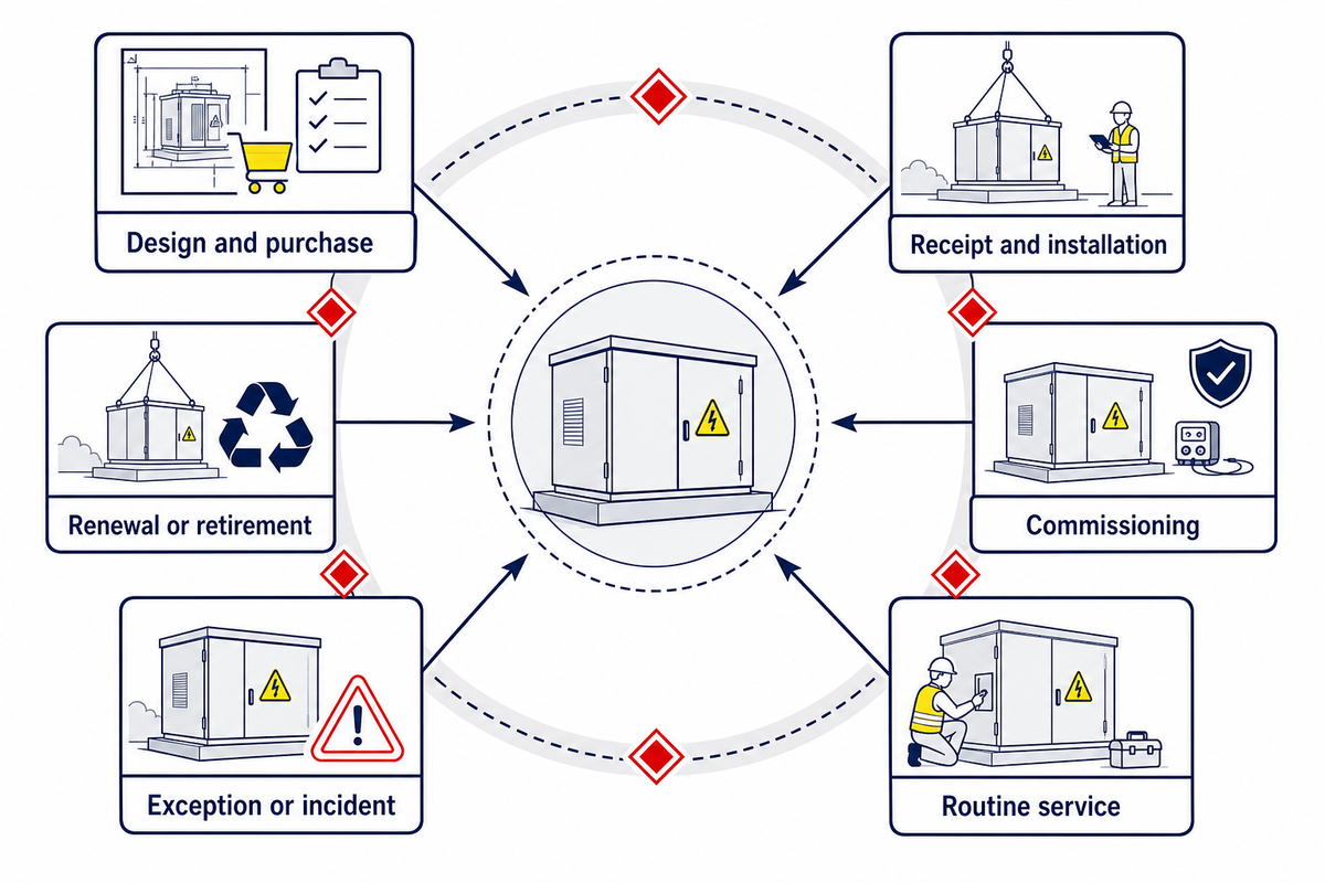
Lifecycle control changes from proving the installed baseline to tracking condition, investigating exceptions, and planning replacement. Those impact and inspection observations feed the lifecycle record, but they don’t set a universal interval, failure rate, or service-life promise for every pad-mounted transformer. Loading, environment, design, ownership rules, fluid system, event history, and test strategy all matter.
| Stage | Owner evidence | Qualified work | Escalation trigger |
|---|---|---|---|
| Design and purchase | Approved basis, drawings, deviations, source documents | Engineering review and factory verification plan | Unresolved interface or unowned requirement |
| Receipt and installation | Shipping condition, identity, storage and as-built records | Authorized placement, cable, grounding, and inspection work | Damage, mismatch, contamination, or incomplete civil work |
| Commissioning | Baseline test and acceptance package | Applicable tests under approved procedures | Result outside acceptance criteria or missing release |
| Routine service | Load, event, inspection, access, and maintenance history | Condition assessment and work defined by the owner program | Trend change, damage, leak, protection event, or record gap |
| Exception or incident | Time, operating state, external observation, alarms, weather, and actions | Isolation, inspection, testing, repair assessment | Safety, environmental, or reliability consequence |
| Renewal or retirement | Condition history, load outlook, compliance and interface changes | Replacement engineering, removal, environmental disposition | Unacceptable risk, obsolete interface, capacity need, or repair decision |
Test results have value when they’re comparable and interpreted in context. One reading can be misleading if the test method, temperature, equipment state, instrument, or baseline differs. Preserve raw results, conditions, exceptions, and the decision made. A clean record strengthens future diagnosis; an invented maintenance interval doesn’t.
What Is Changing in Modern Power Systems, and Why Do Lifecycle Records Matter?
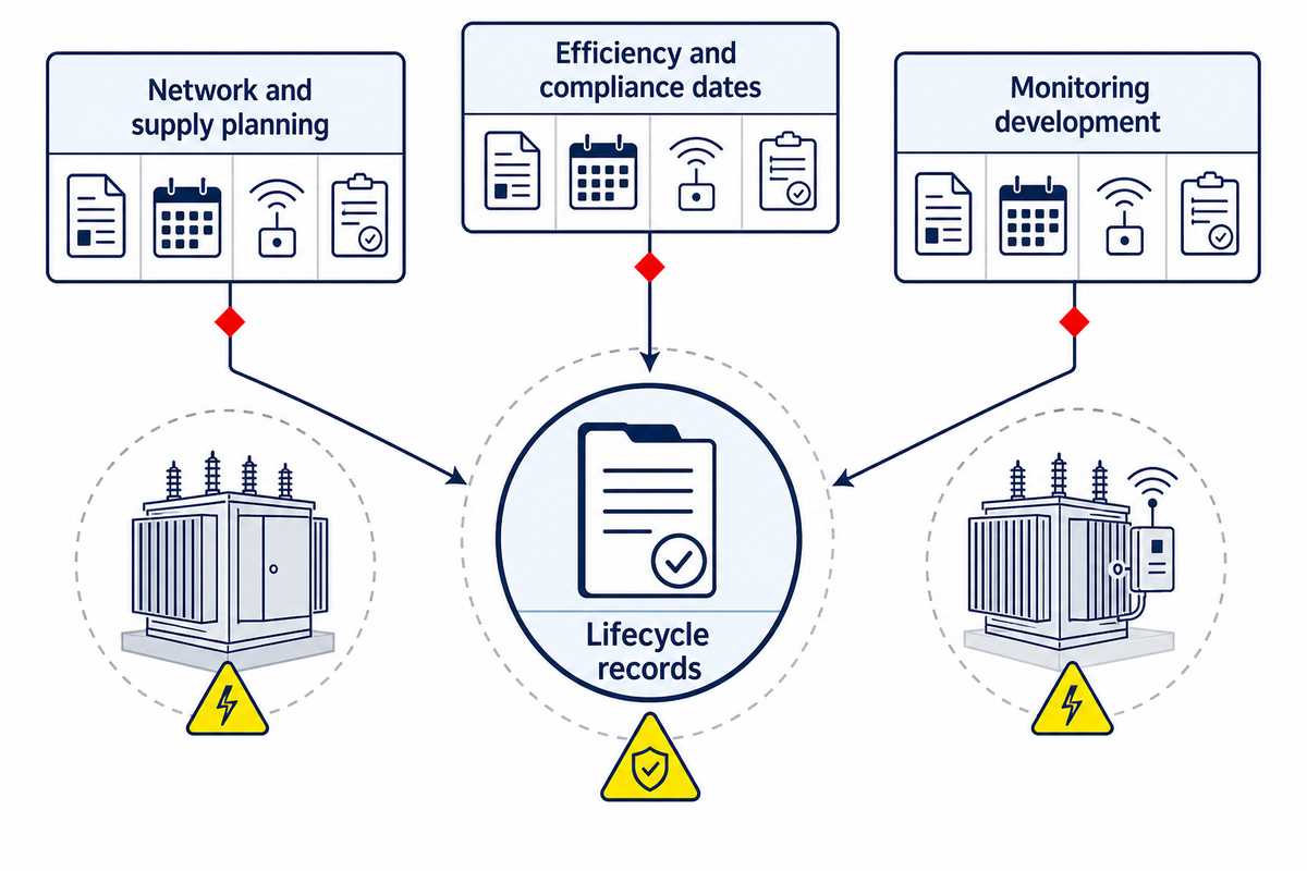
Grid investment, changing loads, efficiency rules, supply constraints, and condition-monitoring research make lifecycle records more valuable, but they don’t change the transformer’s basic voltage-conversion function. Those lifecycle records let teams date current facts and separate them from forecasts, supplier promises, or market-report estimates.
Network and supply planning
The U.S. Department of Energy identifies transformer shortages and long lead times as active supply-chain concerns. That supports earlier interface decisions, not a universal delivery estimate.
Efficiency and compliance dates
Under the 2024 final rule, April 23, 2029 is the compliance date for covered equipment. That 2026 inquiry doesn’t, by itself, erase the date. Recheck current law at purchase release.
Monitoring development
A 2024 federal Phase I award describes current, voltage, and temperature sensing research. It proves funded development, not that every modern unit includes embedded monitoring.
Records connect these drivers. A verified load history supports planning; a complete nameplate and test package supports replacement comparison; a documented fluid and site history informs environmental review; and an explicit responsibility trail prevents an emerging requirement from becoming an unowned assumption.
Frequently Asked Questions
Are pad-mounted transformers oil filled?
Many are liquid-immersed, but the enclosure shape alone does not prove the dielectric fluid or cooling system for a specific unit or site without nameplate evidence.
Many pad-mounted distribution transformers use a dielectric liquid for insulation and heat transfer. Still, cabinet appearance doesn’t establish the fluid type, fire-performance classification, condition, or spill-response requirement. Confirm the nameplate, approved supplier data, safety information, and site rules before making a maintenance, fire, environmental, or replacement decision. Legacy-asset questions may also require records that are irrelevant to a newly manufactured unit.
Are pad-mounted transformers still used?
Yes; they remain part of underground distribution systems, while each site’s phase, feed, interface, rating, and ownership still require approval before procurement or installation begins.
Yes. Utilities and facility owners continue to use pad-mounted transformers where underground distribution and ground-level voltage conversion fit the network. Current U.S. Department of Energy work on distribution-transformer supply constraints also confirms the equipment category remains operationally important. Continued use doesn’t mean one arrangement fits every residential, commercial, campus, or industrial site. The serving utility and responsible engineer must still approve the circuit and service basis.
What are common problems with padmount transformers?
Report leakage, corrosion, damaged access, sound or odor changes, flooding, impact, obstructed work space, and disturbed cable areas; those signs do not identify the root cause.
Observable concerns include fresh fluid, expanding corrosion, damaged doors or locks, a marked sound change, unfamiliar odor, floodwater, vehicle impact, blocked crew access, or disturbed soil near connected cables. None proves a particular internal fault. Members of the public should keep clear and notify the utility or responsible owner. Qualified personnel use operating records, approved tests, and the equipment’s actual status to decide whether isolation, repair, cleanup, or replacement is required.
What is the safe distance from a transformer to a house?
There is no universal distance; use the serving utility’s current written rule, approved site design, equipment access, fire conditions, and local authority requirements before siting.
There’s no single distance that can be copied safely into every project. Placement can depend on the serving utility’s standard, enclosure dimensions and door access, nearby building openings, dielectric fluid and fire conditions, barriers, drainage, property layout, local code, and the authority having jurisdiction. For example, municipal utilities publish different access and combustible-clearance conditions, while an owner-specific federal-facility standard can impose its own work-space and environmental review. Those are scoped examples, not national defaults. Obtain the applicable requirement in writing before fixing the foundation, conduit, fence, landscaping, or building opening. An approved transformer outline proves the equipment footprint; it doesn’t replace civil, fire, utility, or site approval.
Why do some pad-mounted transformers have six primary terminals?
Some three-phase loop-feed arrangements provide incoming and outgoing connection points for each phase; terminal count never grants switching permission or field-work authority for anyone onsite.
On some three-phase loop-feed designs, separate incoming and outgoing connections are provided for each phase. Actual circuit details must be confirmed by the utility one-line diagram, terminal drawing, connector schedule, and operating procedure. Never infer energization, normal-open position, isolation, or permission to operate from the number of terminals.
What is the difference between a pad-mounted transformer and a substation transformer?
A pad-mounted transformer is a ground-level enclosed distribution unit for underground cables; “substation transformer” describes a broader system role or installation context with different interfaces and controls.
A pad-mounted transformer is generally a locked, ground-level distribution unit arranged for underground cable systems and locations where public access must be controlled. “Substation transformer” can describe equipment serving a broader station role with different switching, protection, voltage, access, and enclosure arrangements. Names vary by market. A more reliable boundary comes from the approved one-line diagram, product-standard scope, terminal drawing, site layout, and operating ownership.
Turn the Guide Into a Reviewable Project Handoff
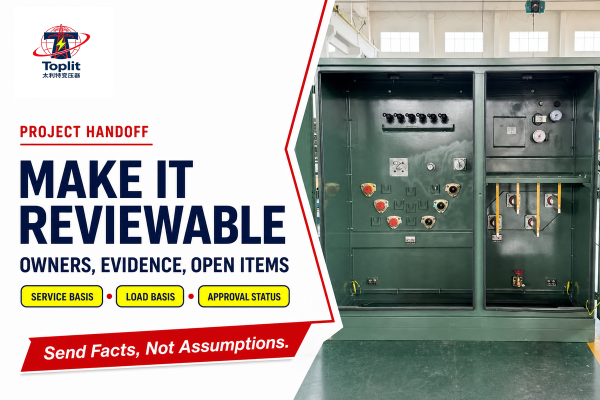
Use this guide to identify missing owners and evidence, not to fill unknown fields with assumptions. Before supplier review, assemble the utility service basis, phase and feed arrangement, required voltages, qualified load basis, site and cable interfaces, applicable standards and editions, testing expectations, energization authority, and any unresolved questions.
Talite Transformer Co., Ltd. has worked in the power-equipment sector for more than three decades and integrates research and development, production, and sales in Nantong, Jiangsu Province. That company background doesn’t prove the fit of an unreviewed design. Product availability, declared ratings, accessories, documentation, price, and lead time must be confirmed for the actual project.
If a qualified load basis is already available, the pad-mounted transformer sizing calculator can organize an initial planning check. Final selection still belongs to the responsible engineer, serving utility, and applicable project authorities.
Have the system basis and open questions ready?
Share the approved service information, load basis, site interfaces, governing documents, and unresolved ownership items. Include the current one-line diagram and approval status when available. Talite can review supplier-side configuration and evidence questions without displacing utility, engineering, or site approval.
Editorial and technical transparency
This guide separates general engineering evidence from project-specific configuration and uses public standard-scope pages, government records, owner standards, and utility safety guidance. It doesn’t claim field measurements, universal clearances, fixed maintenance intervals, or a guaranteed service life.
Key takeaway
A pad-mounted transformer is one link in a controlled distribution system. Understand the energy chain, keep phase and interface labels separate, route approvals through named seats, observe without diagnosing, and preserve the evidence needed for the next lifecycle decision.
References and Sources
- IEEE C57.12.34-2022: three-phase pad-mounted distribution transformer scope
- IEEE C57.12.38-2025: single-phase pad-mounted distribution transformer scope
- IEEE C57.12.28-2023: pad-mounted enclosure integrity scope
- IEEE C57.12.90-2021: liquid-immersed transformer test-code scope
- Federal Register: April 2024 distribution-transformer efficiency final rule
- Federal Register: June 2026 distribution-transformer request for information
- eCFR: 10 CFR Part 431, distribution-transformer provisions
- Lawrence Livermore National Laboratory: January 2026 pad-mounted distribution transformer site standard
- OSHA: insulated elbow and qualified-work interpretation
- U.S. Department of Energy Office of Electricity: distribution-transformer resources
- SELCO: public safety and access around transformer cabinets
- Logan City Light & Power: local pad-mounted transformer requirements
- SBIR.gov: 2024 transformer condition-monitoring Phase I award
![110kV Power Transformer Guide: Specs & Standards [2026]](https://toplit-transformer.com/wp-content/uploads/2026/07/110kv-power-transformer-guide-featured-150x150.png)