Get in touch with Toplit Transformer Co., Ltd Company

Substation Transformers for Power Utilities and Grid Distribution
Substation transformers for utility grid duty, published with the guaranteed no-load loss, load loss, no-load current and impedance for all 28 ratings we build: the numbers your bid evaluation clause actually multiplies. Talite has manufactured power equipment in Hai’an, Nantong for over three decades and ships to more than 30 countries.
- FOR SUBSTATION ENGINEERING
- FOR UTILITY PROCUREMENT
- FOR T&D ASSET PLANNING
A substation transformer is the unit that changes voltage between a transmission or sub-transmission circuit and a distribution circuit inside a substation. It is rated by its primary and secondary voltage pair and by its power carrying capability in kVA or MVA, and in utility service it is specified with guaranteed loss values because those losses are priced into the bid.
- 35 kV / 110–220 kV Voltage classes built
- 800 – 63,000 kVA Parameter-backed capacity
- ONAN / ONAF Cooling, three-phase
- 6.5 – 10.5 % Short-circuit impedance
- 28 ratings Guaranteed losses published
- 11 ratings Shipping size and mass published
Why Substation Transformer Procurement Stalls: Lead Time, Loss Cost, and Offers You Cannot Verify
Utility buyers aren’t short of suppliers. They’re short of offers they can put side by side without guessing at the numbers that decide the award.
Imports were expected to supply 80 % of US power transformers and 50 % of distribution transformers by 2025, with a projected 30 % supply shortfall for power units.
Demand for power transformers has risen 116 % since 2019, while US electricity consumption is up 7 % since 2020 after a decade of decline.
More than $1.8 billion of new North American capacity has been announced since 2023, which narrows the gap without closing it.
A utility-side engineer posting publicly put it plainly: “we’re being told it could now take 72+ weeks for basic electric utility transformers to come in”. Another reported that “It was going to be 2 year leadtime, but Eaton said they could do it in 18”.
- Data centre load. A single hyperscale campus can request more capacity than a mid-sized town, and data centers now sit near the front of most interconnection queues.
- Electric vehicle charging clusters, which raise both peak demand and the duty on local electricity distribution.
- Renewable energy projects: photovoltaic power plants and wind farms need step-up transformers before a single kWh reaches the electrical grid.
- Replacement of ageing electrical infrastructure and power infrastructure across US and European utility grids, much of it installed when power generation was centralised and electrical power flowed one way through simpler power systems.
All four compete for the same factory slots, which is why energy projects that would once have been scheduled around civil works are now scheduled around transformer delivery.
Drawing approval loops are the most common hidden delay in a substation transformer order, because each unresolved specification line (impedance, tap range, bushing arrangement, sound level, test scope) costs a full review cycle. A US utility bid document reviewed for this page allows the buyer two weeks for each drawing approval, and the manufacturer remains bound to the original shipping promise regardless.
Talite’s answer to that isn’t a promise about weeks. It’s to publish the technical particulars a specifying engineer needs before drawings are even issued, so the first submittal is closer to correct.
What the trade press actually recorded in 2025 and 2026
Contrary to the common assumption that lead times only get worse, the September 2025 supply-chain summary published by POWER recorded power transformer lead times easing by ten weeks in a single quarter. A separate 2026 piece in the same title quotes an industry figure arguing that a standard substation power transformer can be delivered 12 to 14 months after the initial engineering drawings are approved.
Where the 12 to 14 months actually starts
Read that second number carefully, because it relocates the problem. If the factory needs 12 to 14 months from approved drawings, then the months spent circulating an incomplete specification are months the schedule can’t recover.
What we do instead of promising weeks
That’s what the rest of this page is: the numbers, in the open. See the US Department of Energy overview of grid modernization for the wider infrastructure context our equipment sits inside.
Talite Substation Transformer Types for Grid Duty: 35 kV and 110–220 kV Three-Phase Ratings
Power and distribution transformers cover a wide span of duty, and this page deals only with the station end of it. Talite builds two families of substation transformer for utility and grid distribution duty, and both are oil-immersed transformers with a cold-rolled grain-oriented silicon steel core.
Two families, split by which loss the design minimises
⤑
The difference between them isn’t only voltage class. It’s which loss the design was engineered to minimise.
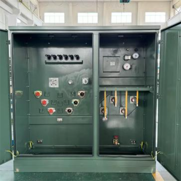
35 kV class, S11 and SF11, 800 to 31,500 kVA ▾
- Series S11, ONAN, oil natural and air natural, 800 to 5,000 kVA, vector group Yd11.
- Series SF11, ONAF, forced air, 6,300 to 31,500 kVA, vector group YNd11.
- High voltage 35 kV or 38.5 kV; low voltage 3.15, 6.3 or 10.5 kV on S11, extended to 3.3, 6.6 and 11 kV on SF11.
- Off-circuit tap ranges of ±5 %, ±2.5 % or ±2 × 2.5 %.
- Short-circuit impedance 6.5 % from 800 to 2,500 kVA, 7.0 % from 3,150 to 5,000 kVA, 8.0 % from 6,300 to 20,000 kVA and 10.0 % from 25,000 to 31,500 kVA.
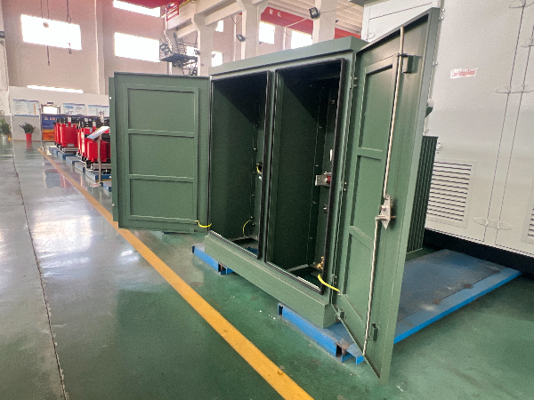
110–220 kV class, 6,300 to 63,000 kVA ▾
- Short-circuit impedance 10.5 % across the whole range.
- Shipping length, width, height and total mass published for every rating, from 21,100 kg at 6,300 kVA to 71,800 kg at 63,000 kVA.
- Designed and tested to IEC 60076 and GB/T 6451.
Rating-level detail for the most requested unit is set out on our 110kV power transformer page, and the wider category sits under power transformers.
Market Definition
Where our range meets what North American buyers usually mean
In US practice the phrase normally points at a unit of roughly 300 to 12,500 kVA with a primary between 2,400 and 34,500 V, built to ANSI/IEEE C57.12.00 and C57.12.36. That is the centre of gravity of the term, and it is worth saying plainly where Talite sits against it.
- Direct overlap: our 35 kV class runs 800 to 31,500 kVA with a 35 or 38.5 kV primary, so it answers the upper half of that band and the sub-transmission end of it.
- Above the band: the 110–220 kV class from 6,300 to 63,000 kVA is capability beyond the usual meaning of the term, not a mismatch with it.
- Outside our scope: every rating here has a low-voltage winding of 3.15 kV or above. If you need a 480 V or 208 V secondary, that is a distribution transformer question and not this page.
- Saying which of the three applies to your feeder takes one line in an email and removes most of the back and forth.
Naming crosswalk: what utilities call these units
Half the confusion in a first enquiry is vocabulary rather than engineering. North American practice, IEC practice and Chinese transformer manufacturing all name the same hardware differently, so the table below states which of our ranges answers which request.
| How the request usually arrives | What is being asked for | Which Talite range answers it |
|---|---|---|
| Substation transformer / substation distribution transformers | Station transformer performing the main voltage change | 35 kV class 800–31,500 kVA; 110–220 kV class 6,300–63,000 kVA |
| High voltage transformers / high-voltage power units | Transmission-connected units above 66 kV | 110–220 kV class |
| Medium-voltage transformers / three-phase transformers | Sub-transmission and MV station duty | 35 kV class, S11 and SF11 |
| Liquid-filled substation transformers | Oil-immersed rather than dry-type construction | Both ranges; all units are oil-immersed |
| Step-down transformers / step-up units | Direction of the voltage change on the same hardware | Both ranges, specified by winding arrangement |
| Unit substation transformers | Transformer section of a close-coupled switchgear line-up | Transformer section only; switchgear supplied by others |
| Pad-mounted transformers / pole-mounted transformers | Downstream distribution hardware, not station duty | Separate distribution ranges, not this page |
Why a vague request cannot be priced
What that table really shows is that a request for transformer solutions or power solutions is rarely specific enough to price, and that a request for a range of transformers isn’t a specification at all. Naming the duty and the guarantee turns a wish into a scope, and it’s why our first reply is usually four questions rather than a brochure of specialized transformers. Tell us the transformer needs behind the enquiry and the answer arrives faster.
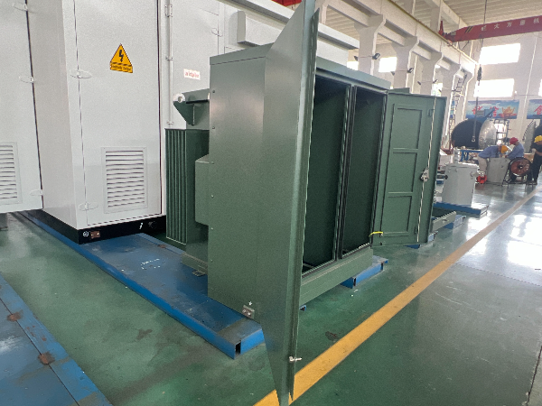
One boundary before you send a specification
One boundary is worth stating before anyone sends a specification. Talite builds the transformer itself, not the North American close-coupled assembly in which a unit substation transformer sits between primary and secondary switchgear. If your scope is that whole line-up, we supply the transformer section and your switchgear vendor supplies the rest.
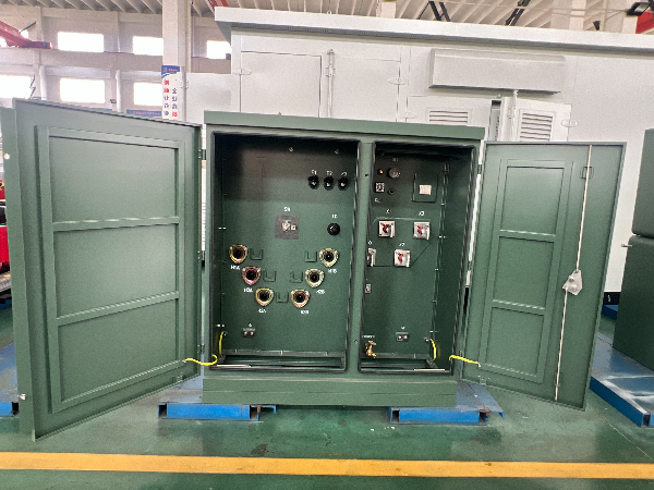
How these units are built
Both Talite families work on the principle of electromagnetic induction, with a laminated grain-oriented steel core linking a primary winding to a secondary winding inside a sealed tank. Every design decision below shows up somewhere in the loss ledger.
What the guarantee is a property of
A loss guarantee isn’t a marketing number; it’s a property of the core and coil assembly and of how heat leaves it. Core loss is fixed by the grain-oriented steel grade and the flux density chosen at design, while load loss is set by conductor cross-section in the primary and secondary winding and by stray losses in the tank and clamps.
Heat dissipation sets the cooling class: ONAN relies on natural oil and air circulation, while ONAF adds fans and lifts the rating of the same core and coil.
Every volt of tap range changes the turns ratio and therefore the current the winding must carry at the extreme tap.
Impedance is a design output, not a preference; pushing it away from the values in our ledger changes short-circuit current and parallel operation on the same bus.
28-Rating Guaranteed Loss Ledger
Why a published guarantee beats a quoted range
Every rating below carries a guaranteed no-load loss, load loss and no-load current from Talite’s own parameter schedule. These are the values a loss evaluation clause multiplies, so they’re the values we publish rather than describe.
28-Rating Guaranteed Loss Ledger — Talite parameter schedule. No-load current is expressed as a percentage of rated current.
That is the point. Loss guarantees that survive a witness test are the only kind worth quoting, and the routine tests behind them follow the measurement procedures in IEEE C57.12.90 and IEC 60076-1. Where a US federal test method applies instead of a bid-specified one, it is the procedure set out in 10 CFR 431.193.
Publishing this ledger is a deliberate trade-off, and it is worth naming. It removes the room a supplier normally has to shade a number late in a negotiation, and it invites any engineer to check our claims against the routine test report.
Voltage Levels and the Loss Step: 35 kV vs 110–220 kV Power Transformers of Equal MVA
Choosing the voltage class by habit is an expensive mistake, and it’s one that stays hidden until the first full year of metered losses. Eight capacities exist in both Talite families, which makes a direct comparison possible using nothing but published guarantees. What falls out is a step that most selection discussions never quantify, because the underlying numbers are rarely available.
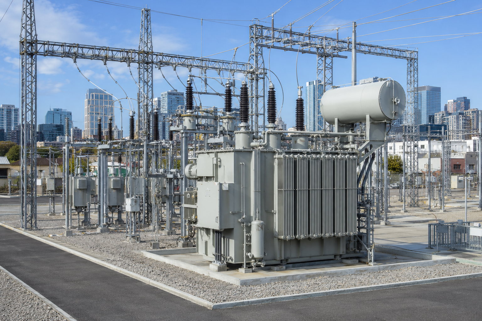
Same rated capacity, two voltage classes. All figures are Talite guaranteed values; the percentages are arithmetic on those values, not estimates.
| Rating | 35 kV no-load | 110–220 kV no-load | Step | 35 kV load | 110–220 kV load | Step |
|---|---|---|---|---|---|---|
| 6,300 kVA | 5.24 kW | 10.0 kW | +90.8 % | 35.0 kW | 36.9 kW | +5.4 % |
| 8,000 kVA | 7.2 kW | 12.0 kW | +66.7 % | 38.4 kW | 45.0 kW | +17.2 % |
| 10,000 kVA | 8.7 kW | 14.2 kW | +63.2 % | 45.3 kW | 53.1 kW | +17.2 % |
| 12,500 kVA | 10.0 kW | 16.8 kW | +68.0 % | 53.8 kW | 63.0 kW | +17.1 % |
| 16,000 kVA | 12.1 kW | 20.0 kW | +65.3 % | 65.8 kW | 77.0 kW | +17.0 % |
| 20,000 kVA | 14.4 kW | 24.0 kW | +66.7 % | 79.5 kW | 91.7 kW | +15.3 % |
| 25,000 kVA | 17.0 kW | 28.4 kW | +67.1 % | 94.0 kW | 110.7 kW | +17.8 % |
| 31,500 kVA | 20.2 kW | 33.5 kW | +65.8 % | 112.0 kW | 133.2 kW | +18.9 % |
■ 35 kV class
■ 110-220 kV class
05101520253035
Rated capacity (kVA), with the no-load loss step below each pair
Figure 1. The voltage-class loss step, plotted from the guaranteed no-load losses in the table above. Every rating in the 110–220 kV class carries between 63 and 91 per cent more core loss than the 35 kV unit of the same capacity, and core loss runs for all 8,760 hours of the year.
Reading the Voltage-Class Loss Step
Moving the same MVA up to the 110–220 kV class costs 63 % to 91 % more no-load loss but only 5 % to 19 % more load loss. Higher system voltage demands more core and more insulation, and core loss is where that shows up. That is a structural reason, not a design preference.
The 8,760-hour asymmetry
No-load loss runs for all 8,760 hours in a year whether the feeder is loaded or not. Load loss varies with the square of loading, so at 50 % load it contributes a quarter of its rated value. A step-down transformer substation that sits lightly loaded most of the year therefore pays the voltage-class penalty far more heavily than a fully loaded industrial feed.
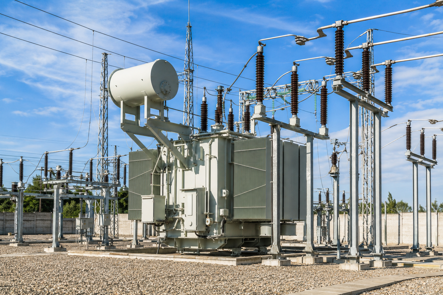
Worked example, 20,000 kVA, 50 % average loading, 8,760 hours
- 35 kV SF11-20000: 14.4 kW × 8,760 = 126,144 kWh of no-load energy, plus 79.5 kW × 0.25 × 8,760 = 174,105 kWh of load energy → 300,249 kWh per year.
- 110–220 kV, 20,000 kVA: 24.0 kW × 8,760 = 210,240 kWh, plus 91.7 kW × 0.25 × 8,760 = 200,823 kWh → 411,063 kWh per year.
- Difference: 110,814 kWh per year for the identical rated capacity, priced against whichever tariff applies to you; the US average sits in EIA Electric Power Monthly Table 5.3.
None of this argues against the higher voltage class. It argues that the class should be chosen from the grid position rather than from habit.
Quote the Voltage-Class Loss Step at your next design review and the loss penalty gets entered in the evaluation instead of discovered in the first full year of operation. Ask for the same-MVA figures for your rating →
Comparing two voltage classes for the same feeder? Ask for the same-MVA loss comparison as a one-page sheet →
Grid-Position Duty Bands: Where the Unit Sits in Power Distribution Decides Which Loss Matters
The most expensive mistake in transformer selection is treating “lowest loss” as a single target. It isn’t one target, and the reason is in the money, not the physics.
What a utility actually pays per kilowatt of loss
US Department of Agriculture Rural Utilities Service guidance publishes an evaluation clause pricing no-load losses at $2,450 per kW and load losses at $1,304 per kW, with auxiliary losses at $756 per kW. A kilowatt of core loss is therefore valued at 1.88 times a kilowatt of winding loss in that bid formula.
Three duty bands, three different right answers
Grid-Position Duty Bands. Peak-efficiency loading is the square root of the ratio of no-load to load loss, calculated from Talite’s published guarantees.
| Band | Typical grid position | Average loading | Dominant loss | Talite range whose design point matches |
|---|---|---|---|---|
| Band A | Generator step-up, continuous industrial process feed | 70–90 % | Load loss | Specify a load-loss guarantee first; confirm against project data |
| Band B | Distribution substation main transformer, urban feeder | 40–60 % | Balanced | 110–220 kV range, peak-efficiency loading 49–52 % |
| Band C | N-1 spare, contingency-sized bank, seasonal peak duty | 15–35 % | No-load loss | 35 kV S11 range, peak-efficiency loading 32–37 % |
| Band B/C edge | Mixed commercial and residential feeder with summer peak | 30–45 % | No-load loss weighted | 35 kV SF11 range, peak-efficiency loading 39–43 % |
Band C – no-load loss dominates
Band B – balanced
Band A – load loss dominates
0%20%40%60%80%100%
Average loading, percent of nameplate
Figure 2. Where each Talite range reaches its best efficiency, set against the three duty bands. The 35 kV S11 units peak inside band C, the SF11 units on the band B and C edge, and the 110–220 kV units inside band B. Peak-efficiency loading is the square root of no-load loss divided by load loss.
Reading a design point off the published guarantees
The peak-efficiency loading of a design is the square root of no-load loss divided by load loss, and it tells you the loading at which that particular unit is at its best. Our published guarantees put the 35 kV S11 units at 32 to 37 %, the SF11 units at 39 to 43 %, and the 110–220 kV units at 49 to 52 %.
One level down the chain
Below the substation fence the same logic runs one level down, where utility transformers serve individual feeders and the loading gets lighter again. Compact grid connections that combine the transformer with switchgear are covered under prefabricated substations.
Why the federal efficiency benchmark uses a light load point
The US Department of Energy test method for distribution transformers determines efficiency at 35 % of nameplate-rated load, not at full load, because light loading is the normal operating condition on much of the distribution system. Substation transformer loading studies show the same picture from the other direction: demand-side management can move a single substation from a load factor near 0.68 to one near 0.88, which changes which loss you should be buying down.
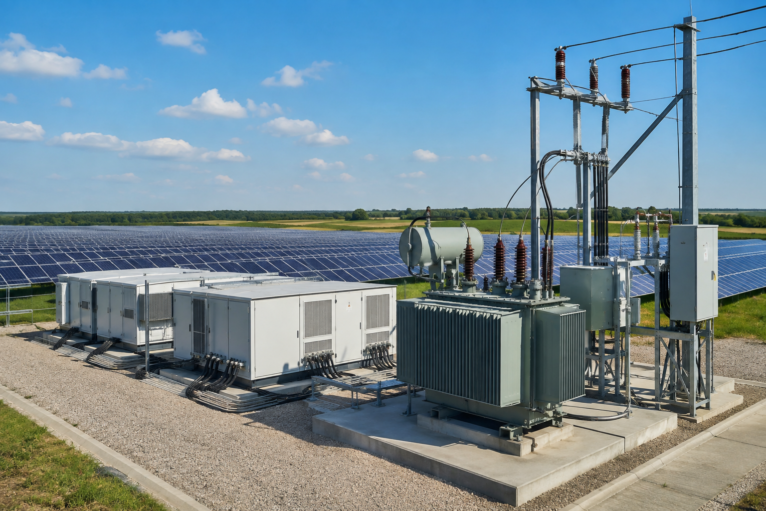
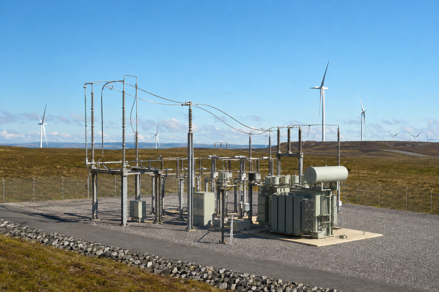
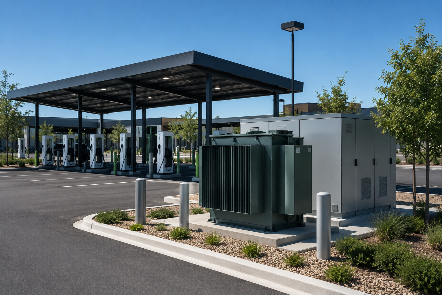
Where the unit sits in the power system
Upstream: transmission or sub-transmission circuit entering the station, typically 110 kV or 220 kV on our larger range.
The unit itself: the substation transformer, carrying the whole station transfer at 6.5 % to 10.5 % impedance.
Downstream: medium-voltage distribution lines leaving the station at 10.5 kV or a similar level, feeding pole-mounted units on the utility pole and pad-mounted units at ground level.
Final step: single-phase or three-phase padmount and pole units taking the last drop to utilisation voltage.
Written out in full, the chain runs: power plants and power stations increase the voltage through a step-up transformer, taking output to transmission voltage for voltage transmission over long distances; a substation transformer performs the first voltage reduction; distribution voltages then travel on overhead power lines or through underground distribution cable across distribution networks; and single-phase transformer units and padmount transformers make the final drop for electric service in residential areas, commercial areas and urban and suburban streets alike. Stepping down voltage levels that many times is what electricity distribution is, and the last pole-mount transformers mounted on a utility pole are what actually reach homes and small businesses, or any other residential or small commercial customers on that feeder. Distributing electrical power as one continuous chain is why a fault in local distribution looks nothing like a fault at the station.
A modern power distribution system steps down at three or four levels, with pad-mounted transformers and pole-mounted transformers serving residential and commercial streets at the bottom. Each stage down that chain runs at a lower average load factor than the one above it, which is why the no-load penalty compounds as you move toward the customer. Feeders carrying distributed renewable energy add a second effect: reverse power flow keeps a transformer energised at low net load for long stretches, and a unit energised at low load is a unit paying its no-load loss for nothing.
$138,948
Evaluated cost of the losses in one 20 MVA 35 kV unit, using the published Rural Utilities Service factors: 14.4 kW × $2,450 plus 79.5 kW × $1,304. That line item is added to the bid price before award.
IEC-to-ANSI Specification Crosswalk for Utility Transformers Built to IEC 60076
This is the section every specifying engineer asks about and almost no supplier page answers, because a North American manufacturer never has to. Talite builds to IEC 60076 and GB/T 6451. If your specification is written to IEEE C57 and NEMA, nine clauses behave differently, and each one changes a number on the test report.
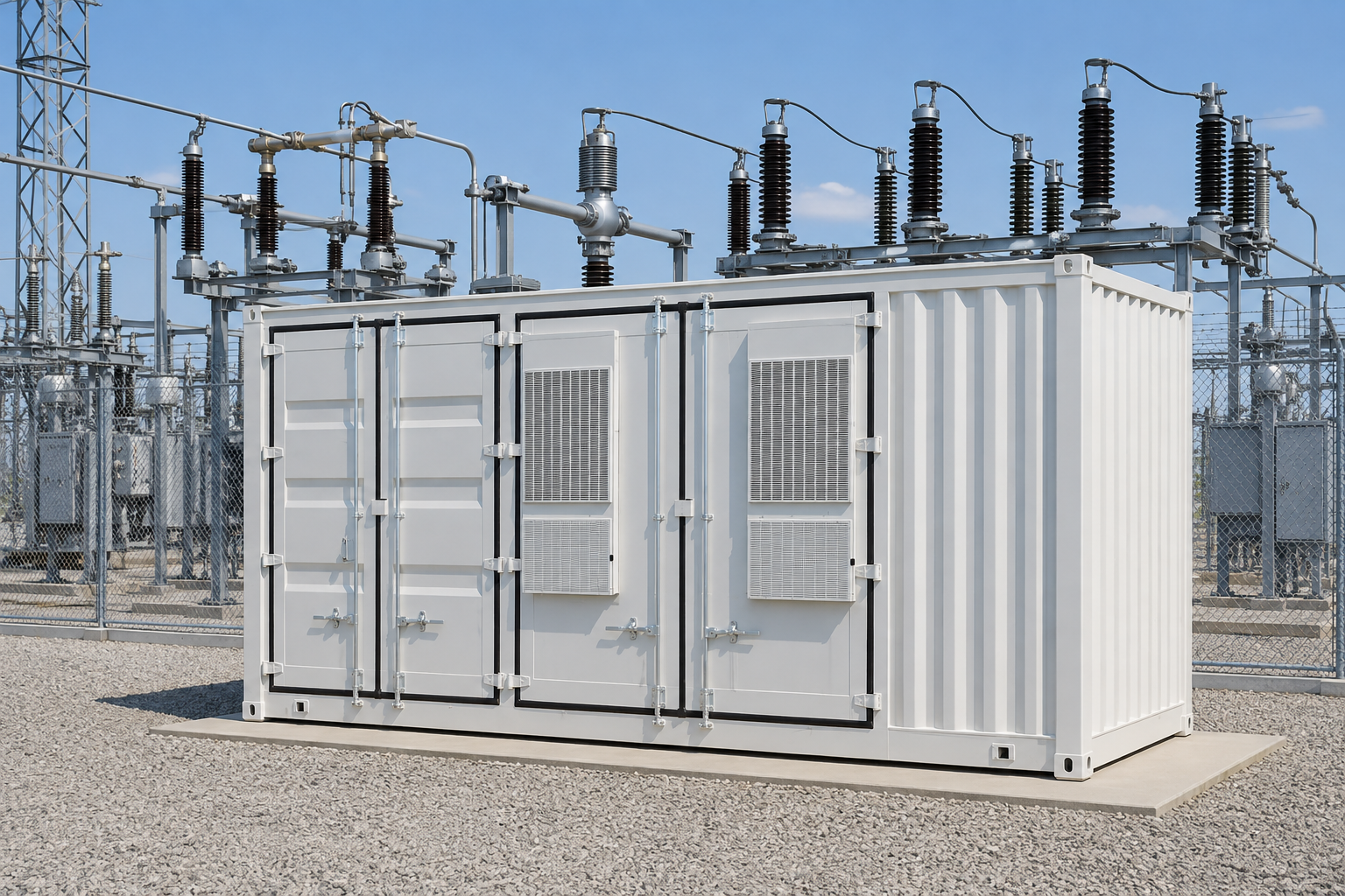
IEC-to-ANSI Specification Crosswalk. Clause comparisons are drawn from the SEAD Distribution Transformers Report Part 2, Test Method Review, Tables 2-1 to 2-3.
| Clause | IEC 60076-1 (2011) | IEEE C57.12.00-2010 | What to restate in the purchase order |
|---|---|---|---|
| Load-loss reference temperature | 75 °C | 85 °C | Name the reference temperature; otherwise two quotes are not comparable |
| No-load-loss reference temperature | 75 °C, measured at factory temperature and not corrected | 20 °C core-loss reference, with a correction equation | State whether a temperature correction is required |
| Loss tolerance | +15 % on an individual loss, total not above +10 % | No-load +10 %, total +6 % | Restate the tolerance you will hold, and the penalty formula |
| Excitation current limit | +30 % of design value | Not specified | Fix the no-load current guarantee explicitly |
| Load-loss test current | May be measured down to 50 % of rated current | Full rated current required | Require full-current measurement if that is your intent |
| Test supply frequency | Within 1 % of rated | Within 0.5 % of rated | Adopt the tighter figure in the test plan |
| Voltage waveshape | Total harmonic content up to 5 % | Not specified | State the acceptable waveform correction limit |
| Three-phase symmetry | Phase voltage spread up to 3 % | Not specified | Carry the IEC limit forward as a test condition |
| Maximum waveform correction | 3 % between average and r.m.s. voltage | Correction above 5 % requires a better waveform | Agree which rule governs before the witness test |
The one line that quietly distorts a bid comparison
Winding resistance rises with temperature, so a load loss referred to 85 °C is larger than the same physical loss referred to 75 °C. An IEC-quoted load loss placed next to an ANSI-quoted one, uncorrected, will look better than it is.
Two rulers, not a trick
That isn’t anybody cheating. It’s two rulers. Talite won’t claim an advantage that comes from a reference temperature, so we state the basis with every guarantee and will restate figures at 85 °C on request.
Where the US Department of Energy efficiency rule actually applies
A distribution transformer under 10 CFR 431.192 must have an input line voltage of 34.5 kV or less, an output line voltage of 600 V or less, 60 Hz operation, and a capacity of 10 to 5,000 kVA for liquid-immersed units. Every substation transformer on this page has a low-voltage winding of 3.15 kV or above, so none of them falls inside that rule.
The practical consequence is the opposite of reassuring: there’s no federal minimum efficiency doing the work for you on these units. What governs is the loss evaluation clause your own specification contains, which is the argument for asking every bidder for guaranteed values in writing.
Two mechanical items round out the crosswalk
Two mechanical items round out the crosswalk, and both are cheap to fix early and expensive to fix late. One US utility bid document is blunt about the first: “All Drawings shall be dimensioned in feet and inches; metric measurements alone will not be acceptable”, with dual dimensioning permitted. Talite issues dual-dimensioned drawings for North American projects, and quotes step down transformer substation ratings in both unit systems.
Route Clearance Register: Shipping Dimensions, Weight, and Installation Access
A substation transformer that can’t reach the pad on the promised date is a schedule failure regardless of how good the losses are. Transport constraints are decided by two numbers per rating, and most suppliers publish neither.
Route Clearance Register — shipping envelope and total mass for the 110–220 kV range. Dimensions are length × width × height.
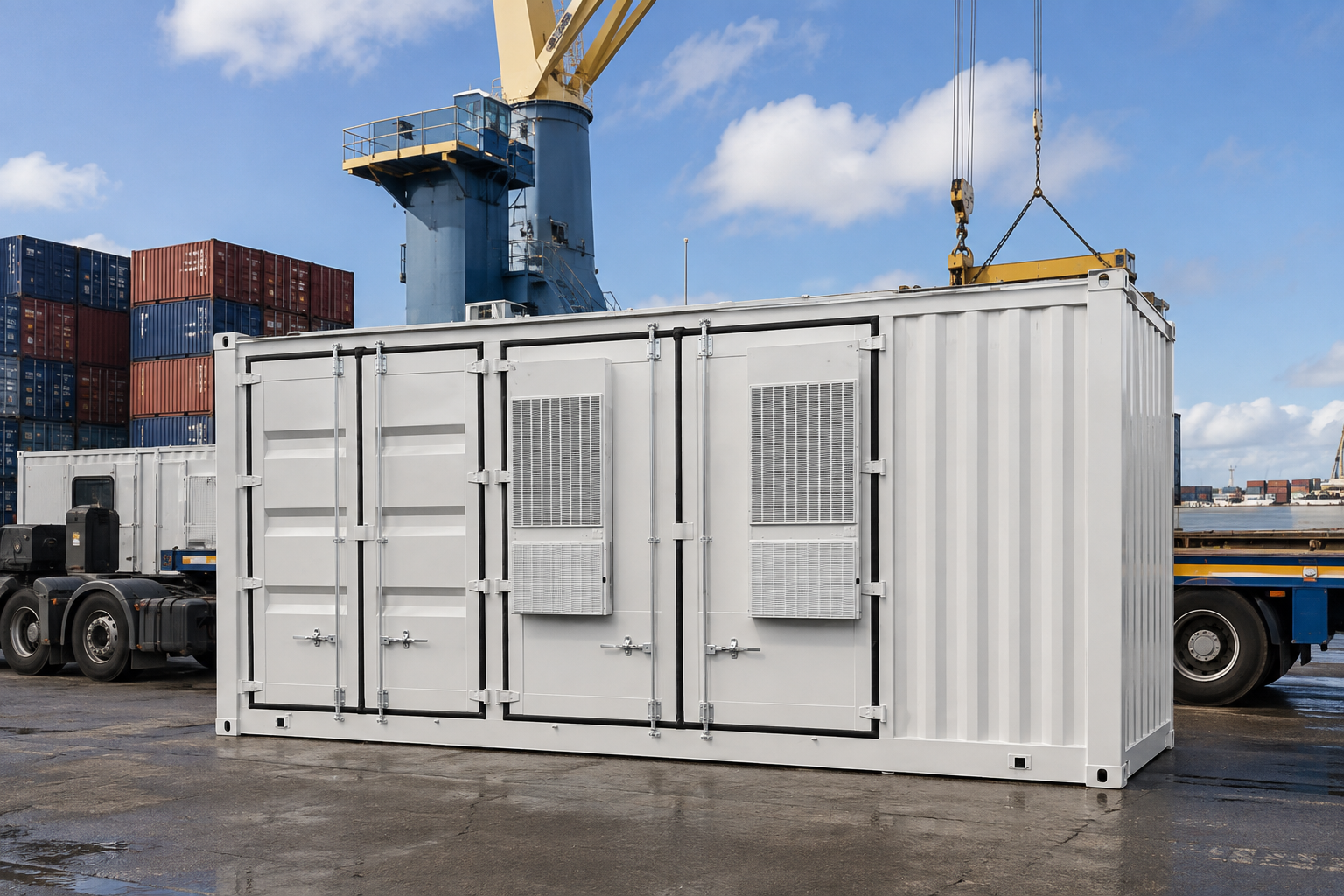
Substation transformer weight is the column that surprises people. Between 6,300 and 63,000 kVA the unit gets 3.4 times heavier while the footprint grows by roughly half, so the binding constraint migrates from gate width to ground bearing and crane capacity, and that has to be reconciled with whatever other substation equipment shares the same access road.
Site access questions worth answering before the order, not after
What’s the lowest overhead clearance on the final approach, and at what loaded deck height?
What’s the permitted axle loading on the last bridge, and does an oversize permit require a survey?
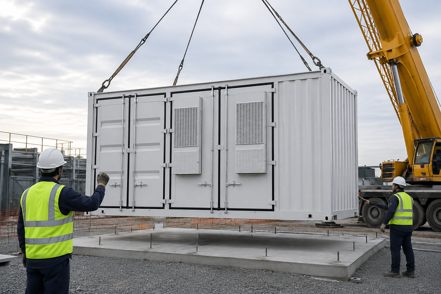
Is there a crane standing position that reaches the plinth centre without crossing a live bus?
Does the foundation design allow for the total mass in the register above plus the oil fill?
US oversize and overweight movements are permitted state by state, and the Federal Highway Administration compilation of state permit practice is the practical starting point for a route study. Talite issues the shipping envelope with the technical proposal so the haulier can begin that study in parallel with drawing approval rather than after it.
The rest of the electrical equipment the transformer has to live with
A substation transformer is never specified alone, and several neighbouring choices constrain it. Getting these settled early is the difference between a clean substation design and a second round of drawings.
Switching and protection: high-voltage circuit breakers on the incoming side, and the circuit breaker interrupting rating that your impedance choice helps to set.
For a new substation the sequence that works is impedance and voltage and current first, then the transformer, then the switchgear line-up around it. Power management and protection settings follow from those three, not the other way round. Knowing how the transformer substation work is sequenced on site is what keeps the commissioning window realistic.
What a Substation Transformer Manufacturer Should Hand You: Test Evidence, Standards, and Claim Boundaries
The approved-vendor barrier, stated plainly
The hardest objection a supplier outside your approved list faces isn’t technical. As one utility engineer put it plainly in a public discussion of a twelve-month lead time: “most commercial developers and utilities will only source from a shortlist of approved manufacturers”.
What the shortlist is really a proxy for
That’s a fair position, and arguing with it is pointless. A productive response works out what the shortlist is a proxy for, then supplies that evidence directly. Buyers screening utility transformer manufacturers are really screening for four things: a test record, a service record, a document pack and a spares path.
The honest version of our documentation position
We name the management systems we operate under and the standards we build to, and we don’t reproduce third-party certificate numbers on a marketing page. If your qualification package requires certificate copies, type test reports or an in-service unit list, we’ll send them against a specific rating and project rather than as a general claim. The Rural Utilities Service loss evaluation guide is the document most of our North American enquiries end up quoting, so that’s where we start.
Routine tests per ANSI C57.12.00 clause 8.2.1, with the buyer free to witness any or all of them.
Sound level tested to NEMA TR-1 as a separately priced adder rather than assumed.
Dissolved gas analysis on the oil 30 days after final assembly, with syringes and shipping containers supplied by the manufacturer.
Nothing ships until the utility approves: an explicit hold point, not a courtesy.
Cooperative utilities add a listing requirement. One public utility district specification reads: “Transformers provided shall conform to Rural Utility Services (RUS) requirements and be listed in the Informational Publication 202-1 – List of Materials.”
IEC 60076
Design and test basis, power transformers
GB/T 6451
Oil-immersed power transformer specification
ISO 9001
Quality management system
ISO 14001
Environmental management system
ISO 45001
Occupational health and safety
CCC
China compulsory certification
Safety and operational conditions that belong in the specification
Fire safety and environmental containment: oil volume, bund capacity and separation distance are site decisions that change the tank and the delivery sequence.
Voltage regulation: whether regulation is handled by an on-load tap changer here or by equipment elsewhere in the distribution systems downstream.
International standards to be applied, and which of them governs if two conflict.
Transformer installation conditions: altitude, ambient range, seismic class and pollution level all derate or reshape the design.
These four decide as much about transformer performance in service as the loss guarantee does, and they’re cheap to settle in week one.
Where our transformers are applied
Talite three-phase oil-immersed units are built to customer specifications for substation applications rather than sold from a catalogue, and the same core ranges serve several duties.
Utility substation duty: kVA-rated and MVA-class substation banks performing voltage reduction between transmission and medium voltage distribution, which is the classic power transmission and distribution interface.
Industrial facilities and industrial applications: three-phase power supplies through a three-phase substation arrangement for process plant, where industrial transformers feed a single site rather than a network.
Power generation interfaces: a three-phase oil-immersed step-up power transformer for generator connection, including photovoltaic power and other renewable energy projects.
Commercial and industrial campuses that take supply at medium voltage and distribute internally, including transformers for commercial estates and, at the specialised end, offshore oil and gas support facilities.
Reliable power distribution depends on matching what the transformer provides to the duty, so we do not offer reconditioned units, rental fleets or stock sales, and we say so plainly because those are different businesses with different risks. What Talite sells is new, custom-designed, energy-efficient transformers built against a specification and a set of guaranteed particulars.
Procurement Guide: Loss-Evaluation Inputs, Lead-Time Drivers, and the RFQ Data We Need
Two costs decide a substation transformer award and only one appears on the invoice. The evaluation clause in a real US utility bid puts it directly: bids are evaluated for equivalent first cost using initial cost, transformer losses, and the cost of financing over a twenty-year evaluation of ownership. The method behind that kind of clause is set out in RUS Bulletin 1724E-301.
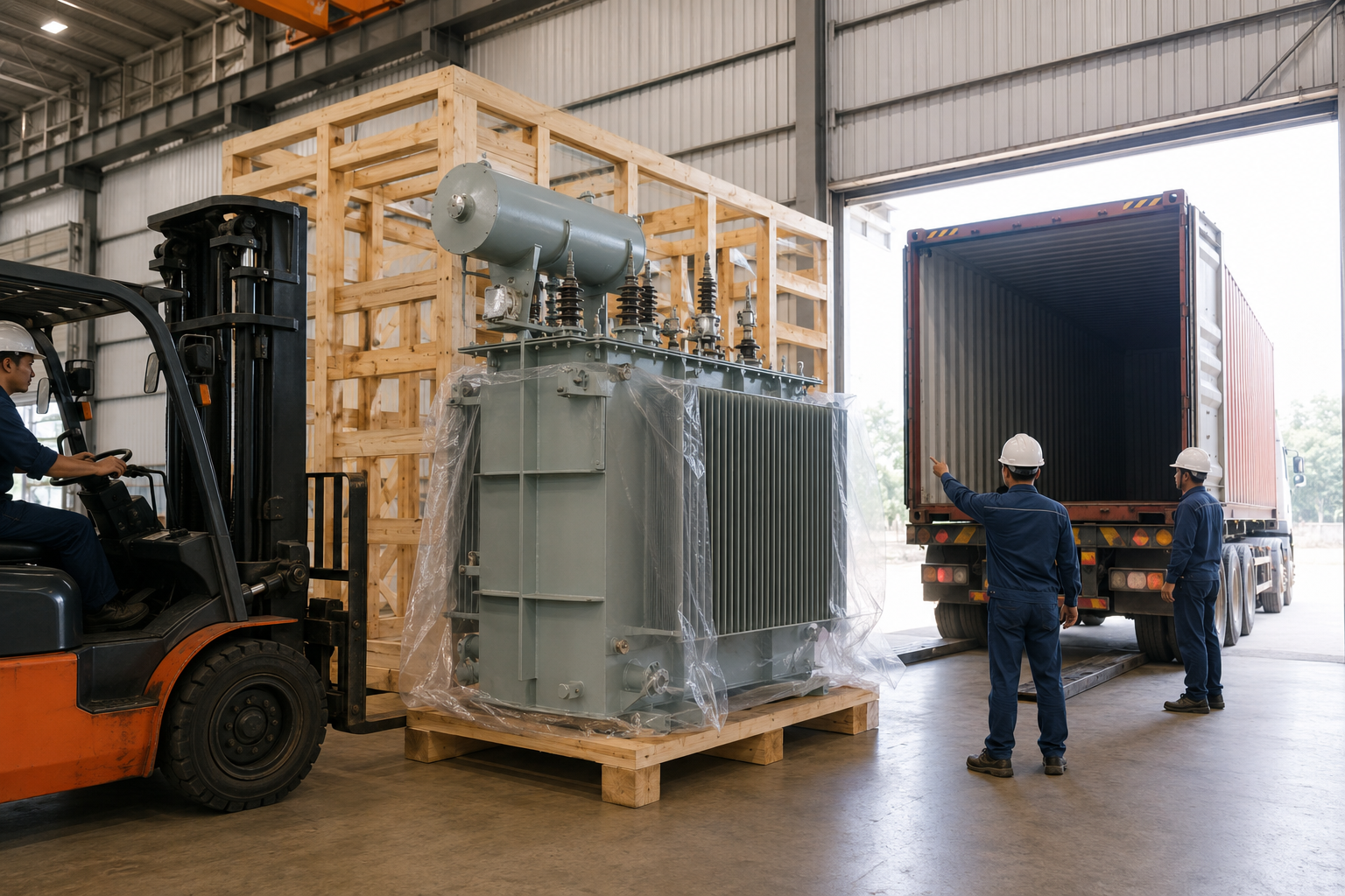
What drives the price, without pretending we can quote it here
Guaranteed loss level.
A tighter no-load guarantee buys more core steel, and grain-oriented electrical steel is a constrained global input.
Voltage class and insulation level.
Moving from 35 kV to 110–220 kV means a different insulation design, not a bigger version of the same one.
Tap changer scope.
An on-load tap changer changes the tank, the control cabinet and the test scope together.
Test and witness scope.
Sound level, temperature rise and short-circuit demonstration are priced items in most utility specifications.
Shipping envelope and site access.
That register above turns into freight, permit and crane costs.
Destination conformity documents.
Certificates, translations and inspection arrangements vary by market.
We don’t publish prices, lead times or warranty periods on this page, because a number without your project data is a guess dressed as a commitment. What we can say is where the schedule is won: the same trade press interview that put factory throughput at 12 to 14 months also located the rest of the calendar in drawing approval, which is under joint control.

In practice an industrial buyer and a municipal utility send us very different first emails, and the trade-off is visible in the numbers. A 2,500 kVA 35 kV unit at 2.56 kW no-load is a one-truck delivery on a 5,010 mm deck, while a 40,000 kVA 110–220 kV unit at 40.4 kW no-load is a permit study before the order. Talite quotes both from the same parameter schedule, so the specification desk and the logistics desk are working from one set of figures rather than two.
Send these and a quotation can be built rather than estimated
- Rated capacity in kVA or MVA, and whether ONAN, ONAF or dual rating applies.
- High-voltage and low-voltage system voltages, vector group and neutral treatment.
- Required short-circuit impedance and its tolerance.
- Tap range and whether tap changing is off-circuit or on-load.
- Your A and B loss evaluation factors, or the evaluation period and energy price you use.
- Test list, witness requirement and the standard the tests must follow.
- Site altitude, ambient range, seismic requirement and pollution level.
- Shipping destination, last-mile constraints and any permit limits already known.
If the requirement sits below the substation level, start instead from our distribution transformer range, and talk to the engineering desk if the split isn’t obvious.
One more item belongs on that list, and it comes from the people who maintain these units rather than buy them. A commissioning and maintenance engineer’s public verdict on one well-known brand reads:
“I can recommend against [brand withheld]. It’s next to impossible to get replacement parts.”
Spares belong in the technical offer
Spare-parts policy is part of the technical offer, not an afterthought to it. Talite quotes bushings, radiators, gauges and tap changer spares alongside the unit rather than after the first failure.
Ready to move from research to a real number? Request an engineering quote for your rating →Grid Distribution Engineering Tools
IEC-to-ANSI Clause Check
Cross-reference IEC and ANSI standards seamlessly to ensure global compliance for your transformer specifications.
Access Tool
Grid-Position Duty Band Finder
Determine the exact duty band requirements based on your specific grid placement and load conditions.
Access Tool
Route Clearance & Permit Pre-Check
Verify transportation route dimensions and local permit requirements for oversized heavy power equipment delivery.
Access Tool
FAQ: Substation Transformers for Utility and Grid Distribution Projects
An electrical substation transformer changes voltage between the incoming and outgoing circuits and carries the full power of that connection. Electrical transformers do this by moving electrical energy through a magnetic field rather than a direct connection.
Three-phase oil-immersed power transformers are the normal choice for utility substation duty, with ONAN cooling at the lower ratings and ONAF above roughly 6 MVA, and Talite supplies 800 to 31,500 kVA in the 35 kV class and 6,300 to 63,000 kVA in the 110–220 kV class. Dry-type units appear indoors and in fire-sensitive rooms, but for outdoor grid duty the liquid-filled design still wins on thermal capacity per unit of cost. Anyone shortlisting substation transformer manufacturers should ask each one which of those two families the quoted price actually belongs to, because the comparison falls apart otherwise.
IEC 60076 and GB/T 6451 govern our design and routine tests, while North American specifications are usually written to IEEE C57.12.00 with test methods in C57.12.90 and sound levels to NEMA TR-1. Nine clauses produce different numbers for the same physical unit, and the crosswalk table above lists every one of them.
Start from winter and summer peak demand measured against the nameplate rating, then decide the loading band the unit will actually live in for the other 8,000 hours of the year, because that band and not the peak alone decides whether you should be buying down no-load loss or load loss. A contingency-sized bank that spends most of its life at 20 to 30 % loading is a different purchase from a continuously loaded industrial feed, even at identical MVA, and our duty band table maps the three common cases against the range whose peak-efficiency loading matches each one.
Not always. A kilowatt of no-load loss is valued at $2,450 against $1,304 for load loss, so the cheapest evaluated unit is the one whose loss split matches the loading.
No, and that surprises most buyers. That federal rule reaches only transformers with an output line voltage of 600 V or less; every rating on this page has a low-voltage winding of 3.15 kV or above. What governs efficiency here is the loss evaluation clause in your own specification, which is the argument for demanding guaranteed values in writing from every bidder.
It depends on how many voltage levels are served and on the contingency policy, and two units each able to carry the load under N-1 is a common arrangement. That count is also how planners find the electrical substation components limiting a station rating.
Yes, provided the purchase order restates the clauses in the crosswalk table, and in practice two of them do most of the damage if they are left alone. The load-loss reference temperature has to be named, because 75 °C and 85 °C are not the same ruler, and the loss tolerance has to be restated because IEC allows +15 % on an individual loss where IEEE holds total losses to +6 %.
We issue dual-dimensioned drawings for North American projects and will restate guaranteed losses on the 85 °C basis so your evaluation compares like with like.
Send the specification and we will mark up the clauses that need a line in the purchase order.